

Page 1

Victoreen® 190N
Portable Neutron Survey Meter
March 2005
Manual No. 190N-1 Rev. 4
©2004, 2005 Fluke Corporation, All rights reserved. Printed in U.S.A.
All product names are trademarks of their respective companies
Operators Manual
Page 2

Fluke Biomedical
Radiation Management Services
6045 Cochran Road
Cleveland, Ohio 44139
440.498.2564
www.flukebiomedical.com/rms
Page 3

Table of Contents
Section 1: Introduction................................................................................................ 1-1
1.1 Product Description ..................................................................................... 1-1
1.2 Specifications............................................................................................... 1-1
1.3 Applications ................................................................................................. 1-3
1.4 Batteries....................................................................................................... 1-3
1.5 Routine Cleaning ......................................................................................... 1-3
1.6 Receiving Inspection.................................................................................... 1-3
1.7 Storage ........................................................................................................ 1-3
1.8 Battery Installation / Replacement ............................................................... 1-4
Section 2: Operation.................................................................................................... 2-1
2.1 Operation ..................................................................................................... 2-1
2.1.1 Time Constants ......................................................................................... 2-1
2.1.2 Integrate / Rate Mode ............................................................................... 2-1
2.2 Operational Checks ..................................................................................... 2-1
2.3 Calibration.................................................................................................... 2-2
Section 3: Troubleshooting ........................................................................................ 3-1
3.1 Troubleshooting ........................................................................................... 3-1
Section 4: Service Information ................................................................................... 4-1
4.1 General ........................................................................................................ 4-1
4.2 Circuit Description........................................................................................ 4-1
4.3 Calibration and Adjustments ........................................................................ 4-1
4.4 Replaceable Parts ....................................................................................... 4-2
i
Page 4

(Blank Page)
Page 5

Introduction
Product Description
1
Section 1
Introduction
1.1 Product Description
The Model 190N is a portable neutron survey meter in the classical Anderson and Braun design
(Snoopy). This survey meter provides mRem rate and dose measurements by combining a moderator /
attenuator probe with all of the features of the Model 190, a “smart” digital survey instrument.
The 190N is lighter in weight than previous designs and ergonomically designed to be easier to carry and
use.
The probe can also be attached to a Model 190AC or the Model 190F Frisker. Both of which can be AC
powered, for continual area monitoring. The Frisker version also includes a metal stand for the 190F.
1.2 Specifications
General The Model 190N is comprised of a neutron moderator / attenuator
containing a BF
proportional counter and a Model 190. A handle and a
3
carrying strap are attached to the moderator. The Model 190 serves as
the readout. It is attached to the moderator as well and can be placed
on either side of the handle. It is also completely removable. A special
probe adapter in the Model 190 is cabled to a preamplifier in a housing
on the moderator which is coupled directly to the BF
tube inside.
3
Readout The Model 190N uses the standard Model 190 as the readout. See the
Model 190 manual for a full description of the audio and visual display
features
Alarm Audio and visual alarms can be programmed into the Model 190N via
the Model 190-1A Infared Communicator
Logging of Data The 190-1A communicator interfaced to a personal computer can be
used to set up data logging
Detector Assembly, Model RP-N The detector assembly is a polyethylene cylinder 9.5 inches long by
8.5 inches in diameter (24.1 x 21.6 cm) containing a BF
proportional
3
counter and neutron energy compensating materials. This
arrangement is based upon the standard reliable Anderson and Braun
design for neutron energy response. The handle is padded for ease of
gripping. An adjustable shoulder strap is provided
Operating Characteristics The BF
BF
3
proportional counter nominally operates at 1150 V
3
Active Length: 2 inches ( 5.08 cm)
Fill Gas: Enriched BF
, 96% Boron 10
3
Gas Pressure: 20 cm Hg.
Resolving Time: 1 microsecond
Plateau Slope: 2% per 100 V
10
Tube Life Expectancy: Greater than 10
counts
Neutron Energy Response The energy range is thermal ( 0.025 eV ) to 15 MeV.
1-1
Page 6
Victoreen 190N
Operators Manual
Accuracy: Within ±10% of theoretical ICRP dose rate.
Recommended Response Time: 24 seconds
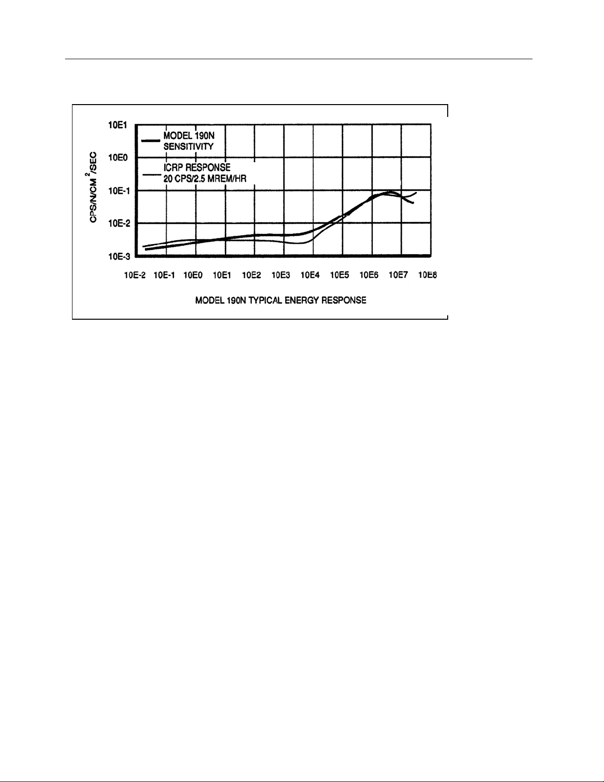
Figure 1-1. Neutron Energy Response
Typical Neutron Sensitivity Nominal 2000 counts per mRem
Range Rate: 0 μRem/h to 75 Rem/h
0 μSv/R to .75 Sv/h
6
0 CPM to 2.5 x 10
CPM
0 CPS to 41,660 CPS
Integrate: 0 μRem to 1000 Rem
0 μSv to 10 Sv,
9
0 to 10
Gamma Sensitivity/Rejection No response in
Counts
137
Cs gamma radiation in fields up to 500 R/h
Accuracy 10% of the theoretical ICRP dose rate
Dimensions Overall Diameter: 12.50 in (31.75 cm)
Overall Length: 10.25 in (26 cm)
Flexibility The Model 190 is detachable from the detector assembly for remote
readings.
It can be held, or can be mounted on either side of the cylinder for
convenient carrying
Miscellaneous Detector Assembly cable length: 4.5 ft (1.3 m). An optional 30 ft (9.14
m) cable
is available
Weight 21 lbs (9.52 kg) (total Model 190 + Detector assembly)
Directionality Less than 20% in three orthogonal directions
Power Requirements Four 9 V alkaline batteries supplied, 100 hours operation
1-2
Page 7

Introduction
Specifications
Calibration Model 190N is calibrated against a NIST traceable “Tissue Equivalent
Proportional Counter” and uses Radium/Beryllium neutrons at a
distance of 100 cm
Temperature Range The Model 190’s operating range is 14°F to 104°F (-10°C to + 40°C).
The detector assembly operating range is –112°F to 176°F (-80°C to +
80°C)
Relative Humidity Range 0 to 95% non-condensing
1.3 Applications
Possible applications for the 190N are:
1. Surveys
2. Area Monitoring
1.4 Batteries
See Model 190 manual for battery replacement.
1
1.5 Routine Cleaning
Do not immerse the Model 190N. The unit is not
waterproof. Liquid could damage the circuits. The
unit should be kept clean and free from dirt and
contamination. The unit may be cleaned by wiping
with a damp cloth using any commercially available
cleaning or decontaminating agent.
CAUTION
1.6 Receiving Inspection
Upon receipt of the package:
1. Inspect the carton(s) and contents for damage. If damage is evident, file a claim with the carrier and
notify the Fluke Biomedical, Radiation Management Service at 440.248.9300.
2. Remove the contents from the packing material.
3. Verify that all items listed on the packing list have been received and are in good condition.
If any of the listed items are missing or damaged,
notify Fluke Biomedical at 440.248.9300.
NOTE
1.7 Storage
Store in an environment free of corrosive materials, fluctuations in temperature and humidity, or vibration
and shock.
1-3
Page 8
Victoreen 190N
Operators Manual
1.8 Battery Installation/Replacement
Four 9 V alkaline batteries are supplied with the Model 190. The battery compartment is located on the
back of the instrument. The compartment will hold up to four batteries. All four batteries must be in place
for proper operation and to avoid damage to the instrument. Use the following procedure to install/replace
the batteries:
CAUTION
To prevent battery leads from shorting on the
battery compartment’s conductive coating, ensure
that all four batteries are installed at all times.
CAUTION
Unit power must be left ON and batteries replaced
one at a time to prevent data loss when the log
mode is activated and logged data is to be
retrieved.
1. Loosen the two quarter turn fasteners securing the battery
compartment cover to the back panel.
2. Remove the battery compartment cover to gain access to the
batteries.
3. Replace the batteries one at a time, observing proper polarity.
4. Replace the battery compartment cover, securing it with the
two quarter turn fasteners.
The unit may make beeping sounds while inserting
the batteries.
WARNING
WARNING
Extreme caution should be used when connecting
the probe to the meter. Improper connection may
result in injury, damage to the instrument, or
damage to the probe.
WARNING
An electrical shock hazard exists between the high
voltage supply and ground.
1-4
Page 9

Introduction
Battery Installation/Replacement
1
CAUTION
To prevent battery leads from shorting on the
battery compartment’s conductive coating, ensure
that all four batteries are INSTALLED at all times.
CAUTION
Unit power must be left ON and batteries replaced
one at a time to prevent data loss when the log
modes activated and logged data is to be retrieved.
CAUTION
The equipment described in this manual is intended
to be used for the detection and measurement of
ionizing radiation. It should be used only by
persons who have been trained in the proper
interpretation of its readings and the appropriate
safety procedures to be followed in the presence of
radiation. Although the equipment described in this
manual is designed and manufactured in
compliance with all applicable safety standards,
certain hazards are inherent in the use of electronic
and radiometric equipment.
NOTE
In the case of an Electro Static Discharge (ESD)
power down of the Model 190N, it is necessary to
reset the unit by cycling the power (turning the unit
off and then on). After reset, the unit will power up
in its normal operating mode
1-5
Page 10

Victoreen 190N
Operators Manual
(Blank Page)
Page 11

Operation
Operation
2
Section 2
Operation
An electrical shock hazard exists between the high
voltage supply and ground.
WARNING
2.1 Operation
The 190 can operate in Rate Mode and display in CPM and mRem /hr units. In Integrate mode the 190
can display in Counts or mRem. Comparable SI units are also provided. The “Mode” button is used to
toggle among allowable display units.
While surveying, should a neutron flux above nominal be observed, the operator can detach the probe
from the Model 190 readout and move away from the area by the length of the cable. A standard and two
longer length cables are available.
In addition to being a survey meter, the probe can be used as a area monitor by purchasing a Model
190AC which is an AC powered version of the Model 190. This eliminates the dependence on batteries.
2.1.1 Time constants
The Model 190 has the capability of acquiring and displaying data with either 24, 12, 6, or 3 second time
constants. The time constant is adjustable by momentarily pressing the “Response Time” button. It is
recommended to use the largest time constant in the lowest rate mode.
2.1.2 Integrate / Rate Mode
Normally surveys are taken in the rate mode, however, the Model 190 can switch between the rate and
integrate mode with the push of the “Rate/Integ” button. The integration starts upon instrument turn on,
and both the integration time and the integrated value are displayed. Should a reset of the integration be
desired, it can be accomplished by holding down the “Resp Time” button for longer than 3 seconds. The
integration will reset and re-start upon let up of the button. Please see the Model 190 manual for a more
detailed discussion.
2.2 Operational Checks
The Model 190 self checks upon turn on.
2-1
Page 12

Victoreen 190N
Operators Manual
2.3 Calibration
The 190N is calibrated against a Tissue Equivalent Proportional Counter using Radium / Beryllium
neutrons at a distance of 100 cm.
The lower discriminator threshold is set at about 1 MeV.
The calibration provides the factor in converting from counts ( CPM ) to Dose Equivalent (mRem/hr). A
quality factor of 8 is assumed for this calculation A Model 190-1A communicator, a personal computer,
and the appropriate software, would give the user the ability to re-calibrate the Model 190, including
entering a new Quality Factor.
2-2
Page 13

Troubleshooting
Troubleshooting
3
Section 3
Troubleshooting
An electrical shock hazard exists between the high
voltage supply and ground.
WARNING
3.1 Troubleshooting
Refer to the Table 3-1 for symptom/cause/corrective action.
Table 3-1. Troubleshooting Table
Symptom Probable Cause Corrective Action
The words “No Detector” is
displayed on the Model 190.
Refer to the Model 190 Manual for other symptoms,
error messages, probable causes and corrective
actions.
Probe Adapter Module not
plugged in.
Probe Adapter Module female
plug not correctly aligned with
the pins in the 190.
NOTE
.
Make Sure The Unit is Off
During The Corrective Action.
Either plug in the module or
remove, check the pins, and
carefully re-plug.
If required, straighten the pins
with a small screwdriver.
3-1
Page 14

Victoreen 190N
Operators Manual
(Blank Page)
Page 15

Service Information
General
4
Section 4
Service Information
WARNING
An electrical shock hazard exists between the high
voltage supply and ground.
4.1 General
The 190N contains 4 functional elements:
1. Model 190 Survey Meter
2. Probe Adapter Module / Preamplifier Assembly
3. Moderator Assembly
4. BF
See the Model 190 manual for all items pertaining to the Model 190. The detector assembly is composed
of a polyethylene cylinder, other neutron moderating and absorbing materials, and a BF
adapter module on the Model 190, the cable, and the preamplifier in the moderator housing couple,
shape, and discriminate the pulses from the BF
Tube
3
tube to the Model 190.
3
tube. The Probe
3
4.2 Circuit Description
Refer to the basic Model 190 manual, part number 190001, for all items pertaining to the Model 190.
The 190PA Probe Adapter/Preamp consists of two circuits boards that are interconnected with a shielded
multi-wire cable. Sheets 1 & 2 of the circuit diagram 190123 shows both of these circuits. In sheet 1, the
first amplifier stage is a charge sensitive amplifier that integrates the radiation produced detector pulse on
capacitor C5. Resistor R5 discharges C5 exponentially. The second amplifier stage shapes the pulse into
approximately 1 microsecond in width.
In sheet two of the circuit diagram, the preamplifier pulse is capacitor coupled to a comparator circuit that
has an amplitude discrimination level of about 80 millivolts. The 93C46 device is an EEPROM that is used
for storage of calibration factors, probe ID and other similar data specific to the operation of the system.
The Model 190 provides high voltage, typically 1100 V, for operation of the detector. Additional filtering of
the high voltage is provided by R1, R2, C2, C3, and C4 as shown is sheet 1 of 190123.
4.3 Calibration and Adjustments
There are no calibrations or adjustments to be made to the detector assembly. For calibrations and
adjustments to the Model 190, see the Model 190 manual.
4-1
Page 16

Victoreen 190N
Operators Manual
4.4 Replaceable Parts
Item Part Number
Model 190 190
RP-N RP-N
Probe Adapter / Preamp 190PA
Adjustable Strap 91-5
Tube 35-190
BF
3
190N Manual 190N-1
190 Manual 190001
4-2
Page 17

(Blank Page)
Page 18

Fluke Biomedical
Radiation Management Services
6045 Cochran Road
Cleveland, Ohio 44139
440.498.2564
www.flukebiomedical.com/rms
 Loading...