

Page 1
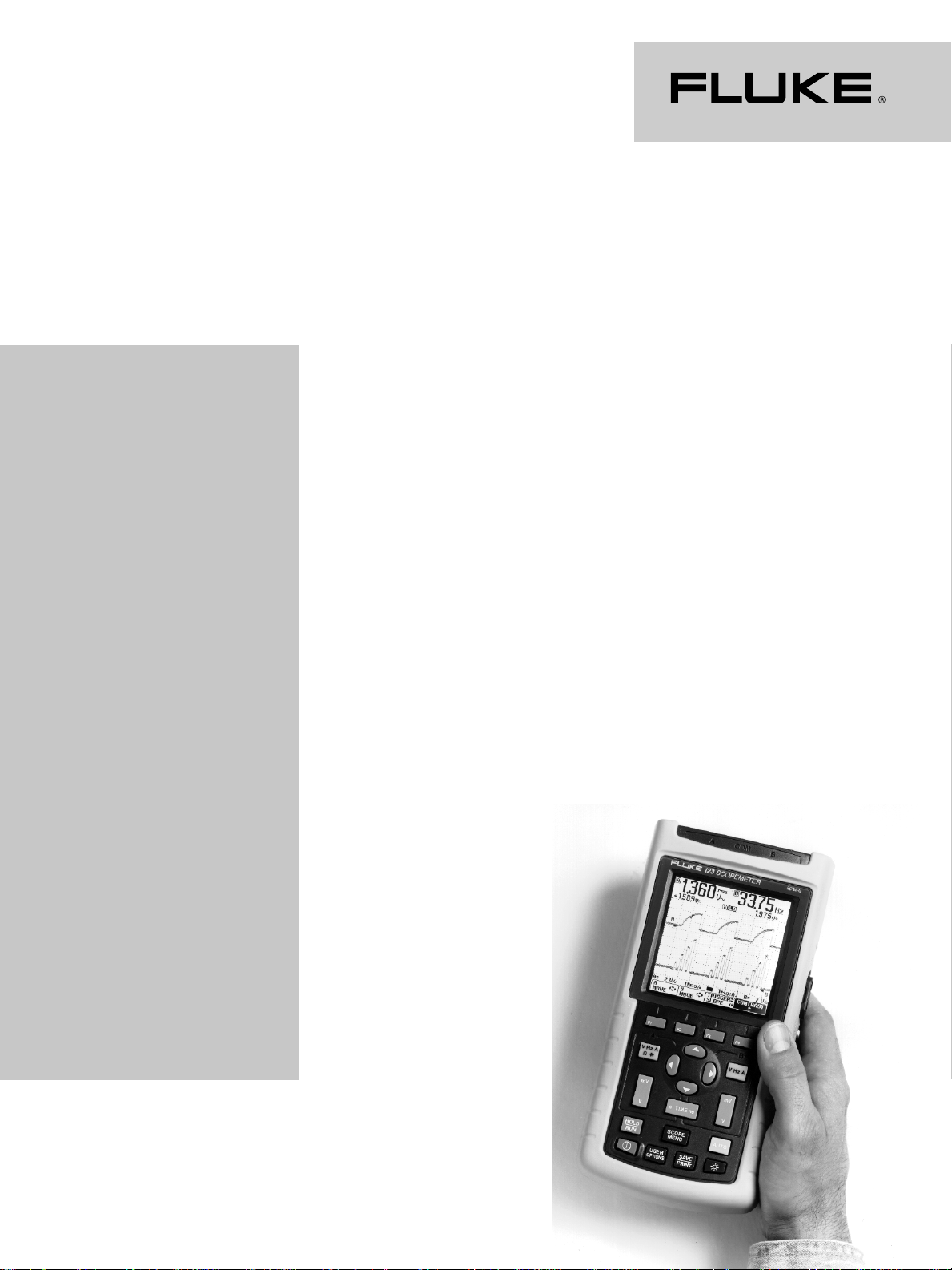
Fluke 123 Industrial
ScopeMeter
Specifications
®
Technical Data
Introduction
Performance characteristics
Fluke guarantees the properties
expressed in numerical values
with the stated tolerance.
Specified non-tolerance numerical values indicate those that
could be nominally expected
from the mean of a range of
identical ScopeMeter test tools.
Environmental data
The environmental data
mentioned in this technical data
are based on the results of the
manufacturer’s verification
procedures.
Safety characteristics
The ScopeMeter 123 test tool
has been designed and tested
in accordance with ANSI/ISA
S82.01-1994, EN 61010.1 (1993)
(IEC 1010-1), CAN/CSA-C22.2
No.1010.1-92, UL3111-1 Safety
Requirements for Electrical
Equipment for Measurement,
Control, and Laboratory Use.
Use of this equipment in
a manner not specified by the
manufacturer may impair
protection provided by the
equipment.
Specifications
Dual input oscilloscope
Vertical
Frequency response
DC coupled:
Excluding probes and test leads:
DC to 20 MHz (-3 dB)
With STL120 1:1 shielded test leads:
DC to 12.5 MHz (-3 dB)
DC to 20 MHz (-6 dB)
With PM 8918 10:1 probe (optional
accessory): DC to 20 MHz (-3 dB)
AC coupled (LF roll off)
Excluding probes and test leads:
<10 Hz (-3 dB)
With STL120: <10 Hz (-3 dB)
With PM 8918: <1 Hz (-3 dB)
Rise time
Excluding probes and test leads:
<17.5 ns
Input impedance
Excluding probes and test leads:
1 MΩ//12 pF
With BB120: 1 MΩ//20 pF
With STL120: 1 MΩ//225 pF
With PM 8918: 10 MΩ//15 pF
Sensitivity: 5 mV to 500V/div
Display modes: A, -A, B, -B
Max input voltage
A, B: 600V rms up to 200 kHz,
derating to 6V rms @ 20 MHz
Max floating voltage
From any terminal to ground:
600V rms up to 400 Hz
Resolution: 8 bit
Vertical accuracy: ±(1% of reading
+ 0.05 range/div)
Max vertical move: ±4 divisions
Horizontal
Acquisition modes
Normal: Equivalent sampling: 20 ns
to 500 ns/div; real time sampling:
1 µs to 5s/div
Single (real time): 1 µs to 5s/div
Roll (real time): 1s to 60s/div
Sampling rate (for both channels
simultaneously): For repetitive
signals (equivalent sampling) up to
1.25 GS/s; real time (normal and
single): 1 µs to 5 ms/div, 25 MS/s;
10 ms to 5s/div, 5 MS/s
Time base accuracy
Equivalent sampling: ±(0.4%
of reading +0.04 time/div)
Real time sampling: ±(0.1%
of reading +0.04 time/div)
Glitch detection: ≥40 ns
@ 20 ns to 5 ms/div; ≥200 ns
@ 10 ms to 5s/div
Glitch detection is always active
Horizontal move, 10 divisions.
Permits shifting of the display
from 0 to 10 division of pre-trigger.
Trigger point will always be visible.
Page 2

Trigger
Mode: Auto, Triggered, Single
Source: A, B, EXT. EXTernal via
optically isolated trigger probe
ITP120 (optional accessory)
Sensitivity A and B
@ DC to 5 MHz: 0.5 divisions or 5 mV
@ 25 MHz: 1.5 divisions
@ 40 MHz: 4 divisions
Slope: Positive, Negative
Video A and B
Modes: Lines, Line Select
Standards: NTSC, PAL, PAL+, SECAM
Polarity: Positive, Negative
Sensitivity: 0.6 divisions sync
Advanced scope functions
Display modes
Normal: Captures up to 40 ns
glitches and displays analog-like
persistence waveform
Smooth: Removes noise from a
waveform
Envelope: Records and displays the
minimum and maximum of waveforms over time
Connect-and-View
Continuous fully automatic
adjustment of amplitude, time base,
trigger levels, trigger gap, hold-off,
and position.
Manual override: Manual adjustment of amplitude, time base,
trigger level, or position.
TM
Dual input
autoranging meter
The accuracy of all measurements
is within ±(% of reading + number
of counts) from 18°C to 28°C.
Add 0.1x (specific accuracy) for
each °C below 18°C or above 28°C.
For voltage measurements with
10:1 probe, add probe uncertainty
+1%. At least one waveform period
must be visible on the screen.
Input A and Input B
DC Voltage (VDC)
Ranges:
500 mV, 5V, 50V, 500V, 1250V
Accuracy: ±(0.5% +5 counts)
Normal mode rejection (SMR):
>60 dB @ 50 or 60 Hz
Common mode rejection (CMRR):
>100 dB @ dc; >60 dB @ 50, 60,
or 400 Hz
Resolution: 5000 counts
True-rms voltages
(VAC and VAC+DC)
Ranges:
500 mV, 5V, 50V, 500V, 1250V
Accuracy for 5% to 100% of range
DC coupled: DC to 60 Hz (VAC+DC)
±(1% +10 counts);1 Hz to 60 Hz
(VAC) ±(1% +10 counts)
AC or DC coupled: 60 Hz to 20 kHz
±(2.5% +15 counts); 20 kHz to
1 MHz ±(5% +20 counts); 1 MHz
to 5 MHz ±(10% +25 counts); 5 MHz
to 20 MHz ±(30% +25 counts)
AC coupled with 1:1 (shielded)
test leads: 60 Hz (6 Hz with 10:1
probe) -1.5%; 50 Hz (5 Hz with
10:1 probe) -2%; 33 Hz (3.3 Hz
with 10:1 probe) -5%; 10 Hz
(1 Hz with 10:1 probe) -30%
Normal mode rejection (SMR):
>60 dB @ 50 or 60 Hz ±1%
Common mode rejection (CMRR):
>100 dB @ dc; >60 dB @ 50, 60,
or 400 Hz
Resolution: 5000 counts
Crest factor: Automatic ranging
on crest factor overload
Peak
Modes: Max peak, Min peak, or
pk-to-pk
Ranges: 50 mV, 500 mV, 5V, 50V,
500V, 1250V
Accuracy: Max peak or Min peak,
5% of full scale; peak-to-peak,
10% of full scale
Resolution: 500 counts
Frequency (Hz)
Ranges: 1 Hz, 10 Hz, 100 Hz, 1 kHz,
10 kHz, 100 kHz, 1 MHz, 10 MHz,
40 MHz (1 Hz and 10 Hz in manual
mode or Auto Set LF ranging only)
Accuracy: @ dc to 1 MHz, ±(0.5%
+2 counts); @1 MHz to 10 MHz
±(1.0% +2 counts); @10 MHz to
40 MHz ±(2.5% +2 counts)
Resolution: 1000 counts
Duty Cycle (DUTY)
Range: 2% to 98%
Accuracy: Same as frequency
Resolution: 0.1%
Pulse Width (PULSE)
Accuracy: Same as frequency
Resolution: 1000 counts
Amperes (AMP)
With optional current probe
Ranges: Same as VDC, VAC,
VAC+DC, or peak
Scale factor: 1 mV/A, 10 mV/A,
100 mV/A, and 1 V/A
Accuracy: Same as VDC, VAC,
VAC+DC, or peak (add current
probe uncertainty)
Temperature (TEMP)
With optional temperature probe
Range: Same as VDC
Scale Factor: 1 mV/°C and 1 mV/° F
Accuracy: Same as VDC (add
temperature probe uncertainty)
Decibel (dB)
0 dBV: 1V
0 dBm (600
referenced to 600Ω or 50Ω dB
on VDC, VAC, or VAC+DC
Resolution: 1000 counts
Ω/50Ω): 1 mW
Crest Factor (CREST)
Range: 1 to 10
Accuracy: ±(5% +1 count)
Resolution: 100 counts
Phase
Modes: A to B, B to A
Range: 0 to 359°
Accuracy: ±(1° +1 count)
Resolution: 1°
Input A
Ohm (Ω)
Ranges: 500Ω, 5 kΩ, 50 kΩ,
500 kΩ, 5 MΩ, 30 MΩ
Accuracy: ±(0.6% +5 counts)
Resolution: 5000 counts
Measurement current: 0.5 mA to
50 nA (decreases with increasing
ranges)
Open circuit voltage: <4V
Continuity (CONT)
Beep: <(30Ω ±5Ω) in 50Ω range
Measurement current: 0.5 mA
Detection of shorts of: ≥1 ms
Diode
Maximum voltage: @ 0.5 mA 2.8V;
@ open circuit 4V
Accuracy: ±(2% +5 counts)
Measurement current: 0.5 mA
Polarity: + on input A, - on COM
Capacitance (CAP)
Ranges: 50 nF, 500 nF, 5 µF,
50 µF, 500 µF
Accuracy: ±(2% +10 counts)
Resolution: 5000 counts
Measurement current: 5 µA to
0.5 mA (increases with increasing
ranges)
Dual slope integrating measurement
with parasitic serial and parallel
resistance cancellation.
Advanced meter functions
Zero set
Set actual value to reference
Fast/Normal/Smooth
Meter settling time
Fast: 1s @ <10 ms/div
Normal: 2s @ <10 ms/div
Smooth: 10s @ <10 ms/div
Page 3

Touch Hold
®
Captures and freezes a stable
measurement result. Beeps when
stable.
TrendPlot
Graphs meter readings of the Min
and Max values from 15s/div (120
seconds) to 2 days/div (16 days)
with time and date stamp.
Automatic vertical scaling and time
compression. Displays the actual
and Min, Max, or AVG reading.
Fixed decimal point
Possible by using attenuation keys.
Miscellaneous
Display
Size: 72 x 72 mm (2.83 x 2.83 in)
Resolution: 240 x 240 pixels
Vertical (scope mode):
1 div = 20 pixels
Horizontal (scope mode):
1 div = 25 pixels
Backlight: Cold Cathode
Fluorescent (CCFL)
Power
External:
Via PM 8907 Power Adapter
Input voltage:10 to 21V dc
Power: 5W typical
Input connector: 5 mm jack
Internal:
Battery power: Rechargeable
NiCd 4.8V
Operating time: 4 hours with
bright backlight; 5 hours with
dimmed backlight
Charging time: 4 hours with test
tool off; 7 hours with test tool on;
12 hours with refresh cycle
Allowable ambient temperature
during charging: 0°C to 45°C
(32°F to 104°F)
Memory
Number of screens: 2
Number of user setups: 10
Mechanical
Size: 232 x 115 x 50 mm
(9.1 x 4.5 x 2 in)
Weight: 1.1 kg (2.5 lb); includes
battery pack
Interface
RS-232, optically isolated.
To printer: Supports Epson FX, LQ,
and HP Deskjet
Postscript. Serial via PM 9080
(optically isolated RS-232 adapter/
cable, optional). Parallel via PAC91
(optically isolated print adapter
cable, optional).
To PC: Dump and load settings and
data. Serial via PM 9080 (optically
isolated RS-232 adapter/cable,
optional).
®
, Laserjet®, and
Environmental
Environmental reference
MIL 28800E, Type 3, Class 3,
Style B
Temperature
Operating:
0°C to 50°C (32°F to 122°F)
Storage:
-20°C to 60°C (-4°F to 140°F)
Humidity
Operating: @0°C to 10°C (32°F to
50°F), non-condensing; @10°C to
30°C (50°F to 86°F) 95%; @30°C to
40°C (86°F to 104°F) 75%; @40°C
to 50°C (104°F to 122°F) 45%
Storage: @-20°C to 60°C
(-4°F to 140°F), non-condensing
Altitude
Operating: Max input and floating
voltage: 600V rms up to 2 km
Storage: 12 km (40,000 ft)
Vibration: Max 3g
Shock: Max 30g
Electromagnetic Compatibility
(EMC)
Emission: EN 50081-1 (1992):
EN55022 and EN60555-2
Immunity: EN 50082-1(1992):
IEC1000-4-2, -3, -4, -5
Enclosure Protection: IP51
Safety
Ratings: Designed for
measurements on 600V rms
Category III installations, Pollution
Degree 2, per:
ANSI/ISA S82.01-1994
EN61010-1 (1993) (IEC1010-1)
CAN/CSA-C22.2 No.1010.1-92
UL3111-1
Max input voltage input A and B:
Direct on input or with leads 600V
rms up to 200 kHz, derating to
6V rms @ 20 MHz
With Banana-to BNC Adapter
BB120: 300V rms up to 200 kHz,
derating to 6V rms @ 20 MHz
Max floating voltage:
From any terminal to ground
600V rms up to 400 Hz
CE marking
Conforms with the EEC directive
89/336. See additional information
shown in Table 1 and Table 2.
Warranty
Three years on parts and labor.
Quality system certified to
ISO 9001.
Accessories
Supplied complete with PM 8907
Line Adapter/Charger, STL120
Shielded Test Leads, AC120
Alligator Clips, HC120 Hook Clips,
one BB120 Shielded BNC Adapter,
BP120 Rechargeable Battery Pack,
and users manual.
Table 1. Trace disturbance with STL120
No visible disturbance E = 3V/m E = 10V/m
Frequency range 10 kHz to 27 MHz 50 mV/div to 500V/div 500 mV/div to 500V/div
Frequency range 27 MHz to 1 GHz 50 mV/div to 500V/div 50 mV/div to 500V/div
Indicated ranges are without visible disturbance.
Table 2.
Disturbance less than 10% of full scale E = 3V/m E = 10V/m
Frequency range 10 kHz to 27 MHz 10 mV/div to 20 mV/div 50 mV/div to 200 mV/div
Frequency range 27 MHz to 1 GHz 5 mV/div to 20 mV/div ——
Not indicated ranges (-) have no visible disturbance, indicated ranges show disturbance
less than 10% of full scale.
Table 3. Multimeter disturbance (VDC, VAC, OHM, CAP) with TL120
Disturbance less than 1% of full scale E = 1V/m E = 3V/m
Frequency range 10 kHz to 27 MHz (with STL120)
VDC, VAC, VAC+DC 500 mV to 1.25 kV 500 mV to 1.25 kV
OHM, CONT, DIODE 500Ω to 30 MΩ 500Ω to 30 MΩ
CAP 50 nF to 500 µF 50 nF to 500 µF
Frequency range 27 MHz to 1 GHz (with STL120)
VDC, VAC, VAC+DC 500 mV to 1.25 kV 500 mV to 1.25 kV
OHM, CONT, DIODE 500Ω to 30 MΩ 500Ω to 30 MΩ
CAP 50 nF to 500 µF 50 nF to 500 µF
For conditions not specified in Tables 1 to 3, a susceptibility effect of more than 10% is possible.
Page 4

ScopeMeter® test tool Selection Guide
Fluke 105B Fluke 99B Fluke 96B Fluke 92B Fluke 123
Oscilloscope Features
Bandwidth 100 MHz 100 MHz 60 MHz 60 MHz 20 MHz
Maximum repetitive sample rate 5 GS/s 5 GS/s 2.5 GS/s 2.5 GS/s 1.25 GS/s
Number of channels 2 + Ext. Trig 2 + Ext. Trig 2 + Ext. Trig 2 + Ext. Trig 2
Rise time <3.5 ns <3.5 ns <5.7 ns <5.7 ns <17.5 ns
Time/division 5 ns-60 sec 5 ns-60 sec 10 ns-60 sec 10 ns-60 sec 20 ns-60 sec
Volts/division 1 mV-100V 1 mV-100V 5 mV-100V 5 mV-100V 5 mV-500V
Record length (bytes) 512 512 512 512 512
ScopeRecord™ 30k memory
Screen/waveform/set-up memories 10 / 20 / 40 10 / 20 / 40 5 / 10 / 20 - / - / - 2 / - / 10
Continuous AUTOSET
Glitch capture down to 40 ns
Video triggering; interlaced, NTSC, PAL,
SECAM (line and field selectable)
Video triggering; high resolution video,
non-interlaced (line selectable)
External triggering
Pre and post trigger adjustment in divisions -20 to +640 -20 to +640 -20 to +640 -20 to +640 -10 to +10
Envelope Mode (Min/Max) and Waveform Smooth
Measure amps with optional current clamps
Cursor measurements
Waveform math (integrate, +, -, filter)
Autoranging True-rms Multimeter Features
Number of DMM channels 11112
Display readout (basic dc accuracy 0.5%) 3000 counts 3000 counts 3000 counts 3000 counts 5000 counts
Advanced measurements (temp., current, % duty,
pulse width, dB, Hz, amps, and more)
Diode Test and Continuity Beeper
Min Max TrendPlot with time and date stamp 1 channel 1 channel 1 channel 1 channel 2 channel
DMM measurements with waveform
Capacitance 50 nF-500 µF
General Features
High-contrast, gray scaled backlit display
Waveform and screen image transfers to a PC
and remote operation
Screen image transfers to a PC
4 hour NiCad battery operation and charger
Optically isolated RS-232C interface for printer and
PC interface cable optional (included in 105B)
On-line help (information)
EN61010-1 approved and UL listed for 600 volts rms,
CSA certified
Automatic setup measurements 40 40 40 28 26
Signal generator/component tester output
Size (HxWxD) 10.2 x 5.1 x 2.4 in 10.2 x 5.1 x 2.4 in 10.2 x 5.1 x 2.4 in 10.2 x 5.1 x 2.4 in 9.1 x 4.5 x 2.0 in
Weight 4 lb/1.8 kg 4 lb/1.8 kg 4 lb/1.8 kg 4 lb/1.8 kg 2.5 lb/1.2 kg
PC software for Windows + PM 9080 cable
Hard carrying case
= Standard feature
•
+ = Option
•••
••••
Connect-and-
View
™
•••••
•••••
••••
••••
+
•••••
•••••
•••
••
•••••
•••••
•••••
•••••
••• •
•••••
••••
5 hours
•••••
••••
•••••
••
260x130x60 mm 260x130x60 mm 260x130x60 mm 260x130x60 mm 232x115x50 mm
•
•
++ +
++++
Fluke Corporation
PO Box 9090, Everett, WA USA 98206
Fluke Europe B.V., PO Box 1186, 5602 BD, Eindhoven, The Netherlands
For more information call: U.S.A. (800) 443-5853 or Fax (206) 356-5116
Europe (31 40) 2 678 200 or Fax (31 40) 2 678 222
Canada (905) 890-7600 or Fax (905) 890-6866
Other countries (206) 356-5500 or Fax (206) 356-5116
Web access: http://www.fluke.com
©1997 Fluke Corporation. All rights reserved.
Printed in U.S.A. 3/97 J0661UEN Rev A Printed on recycled paper.
 Loading...