

Page 1

110/113/114/115/117
True-rms Multimeter
Users Manual
(Simplifed=
hinese) (Simplifed=hinese)
March 2020
© 2020 Fluke Corporation. All rights reserved. Specifications are subject to change without notice.
All product names are trademarks of their respective companies.
Page 2

LIMITED WARRANTY AND LIMITATION OF LIABILITY
LIMITED WARRANTY AND LIMITATION OF LIABILITY
This Fluke product will be free from defects in material and workmanship for three years from the date of purchase. This
warranty does not cover fuses, disposable batteries, or damage from accident, neglect, misuse, alteration, contamination, or
abnormal conditions of operation or handling. Resellers are not authorized to extend any other warranty on Fluke’s behalf. To
obtain service during the warranty period, contact your nearest Fluke authorized service center to obtain return authorization
information, then send the product to that Service Center with a description of the problem.
THIS WARRANTY IS YOUR ONLY REMEDY. NO OTHER WARRANTIES, SUCH AS FITNESS FOR A PARTICULAR
PURPOSE, ARE EXPRESSED OR IMPLIED. FLUKE IS NOT LIABLE FOR ANY SPECIAL, INDIRECT, INCIDENTAL OR
CONSEQUENTIAL DAMAGES OR LOSSES, ARISING FROM ANY CAUSE OR THEORY. Since some states or countries do
not allow the exclusion or limitation of an implied warranty or of incidental or consequential damages, this limitation of liability
may not apply to you.
vision.
11/99
Fluke Corporation
P.O. Box 9090
Everett, WA 98206-9090
U.S.A.
Fluke Europe B.V.
P.O. Box 1186
5602 BD Eindhoven
The Netherlands
ǶǶǶ «ǼȓȦȒ ǹǰǨDZȅǹ»
125167, ȋ. ǴȖșȒȊȈ,
dzȍȕȐȕȋȘȈȌșȒȐȑ ȗȘȖșȗȍȒȚ ȌȖȔ 37,
ȒȖȘȗțș 9, ȗȖȌȢȍȏȌ 4, 1 ȥȚȈȎ
Page 3

Table of Contents
Title Page
Introduction ........................................................................................................... 1
How to Contact Fluke............................................................................................ 1
Safety Information................................................................................................. 1
Unsafe Voltage ..................................................................................................... 1
Test Lead Alert...................................................................................................... 1
Product Familiarization ......................................................................................... 2
Features........................................................................................................... 2
Display............................................................................................................. 3
Terminals ......................................................................................................... 4
Error Messages ............................................................................................... 5
Battery Saver™ (Sleep Mode)......................................................................... 5
MIN MAX AVG Recording Mode ..................................................................... 5
Display HOLD .................................................................................................. 6
Backlight .......................................................................................................... 6
Manual and Autoranging.................................................................................. 6
Power-Up Options ........................................................................................... 6
Making Basic Measurements........................................................................... 7
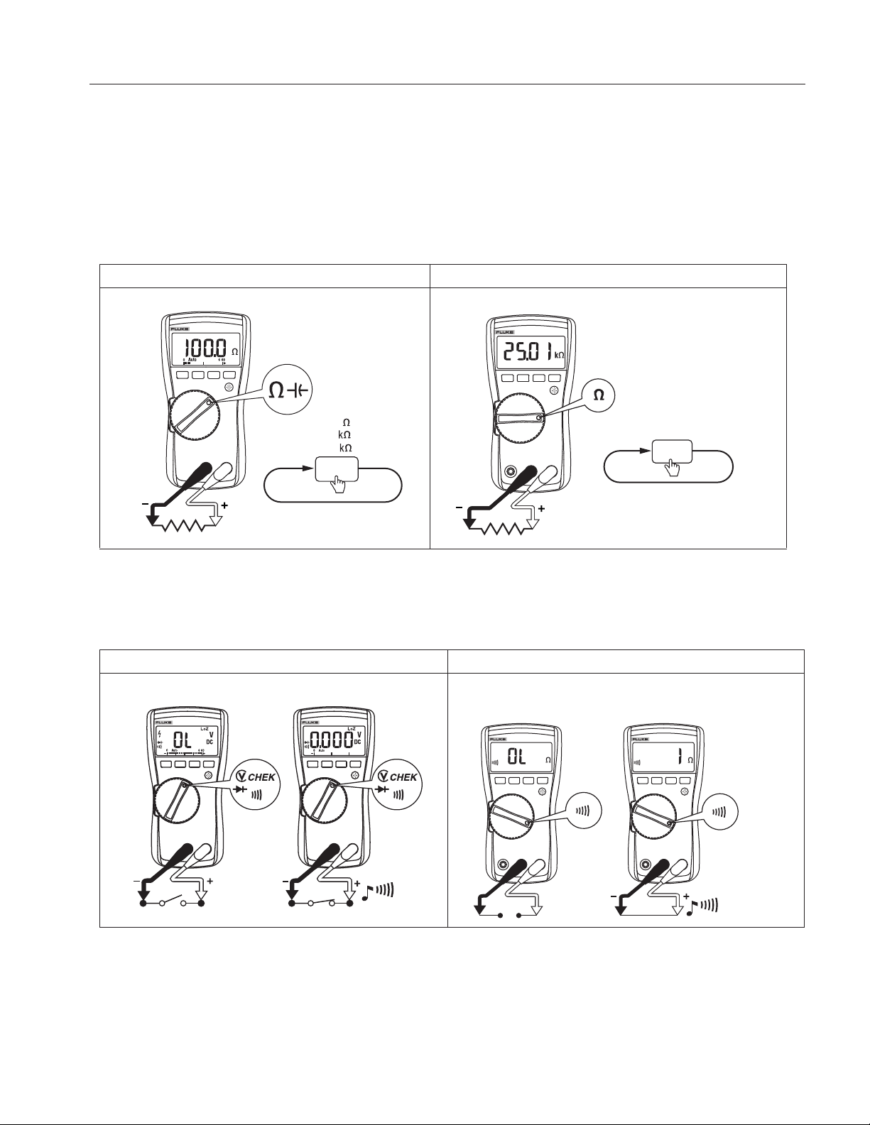
Measuring Resistance ................................................................................ 7
Testing for Continuity.................................................................................. 7
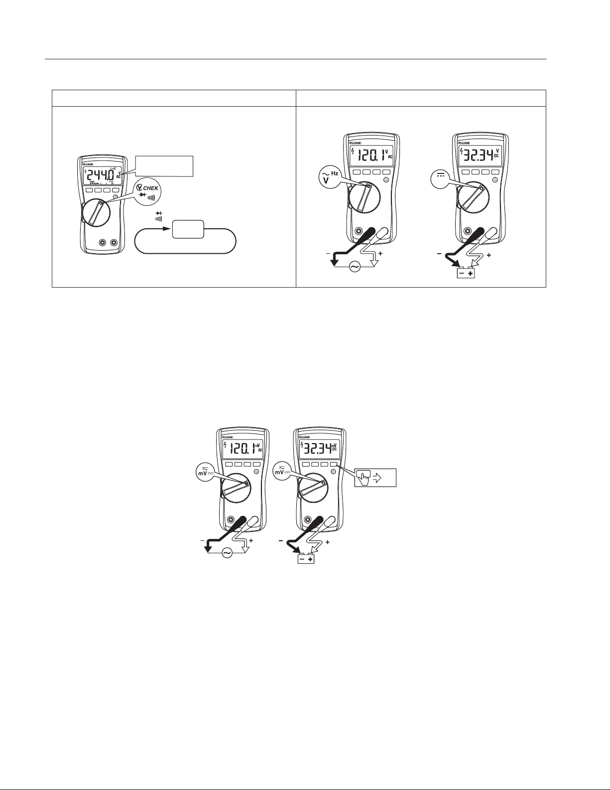
Measuring AC and DC Voltage .................................................................. 8
Using Auto Volts Selection (114, 117)........................................................ 8
Measuring AC and DC Millivolts (110, 114, 115, 117)................................ 8
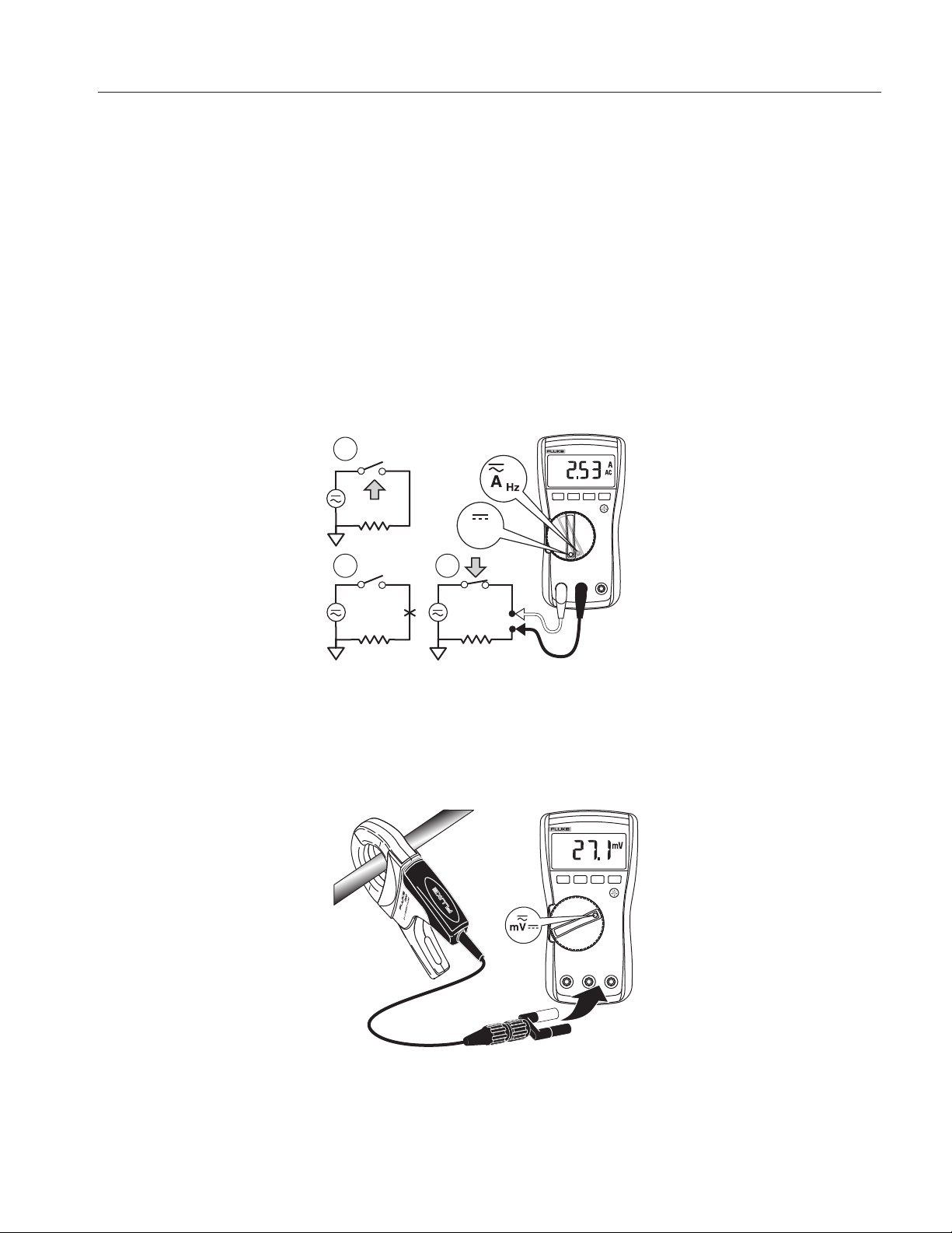
Measuring AC or DC Current (115, 117) .................................................... 9
Measuring Current above 10 Amps (110, 114, 115, 117) .......................... 9
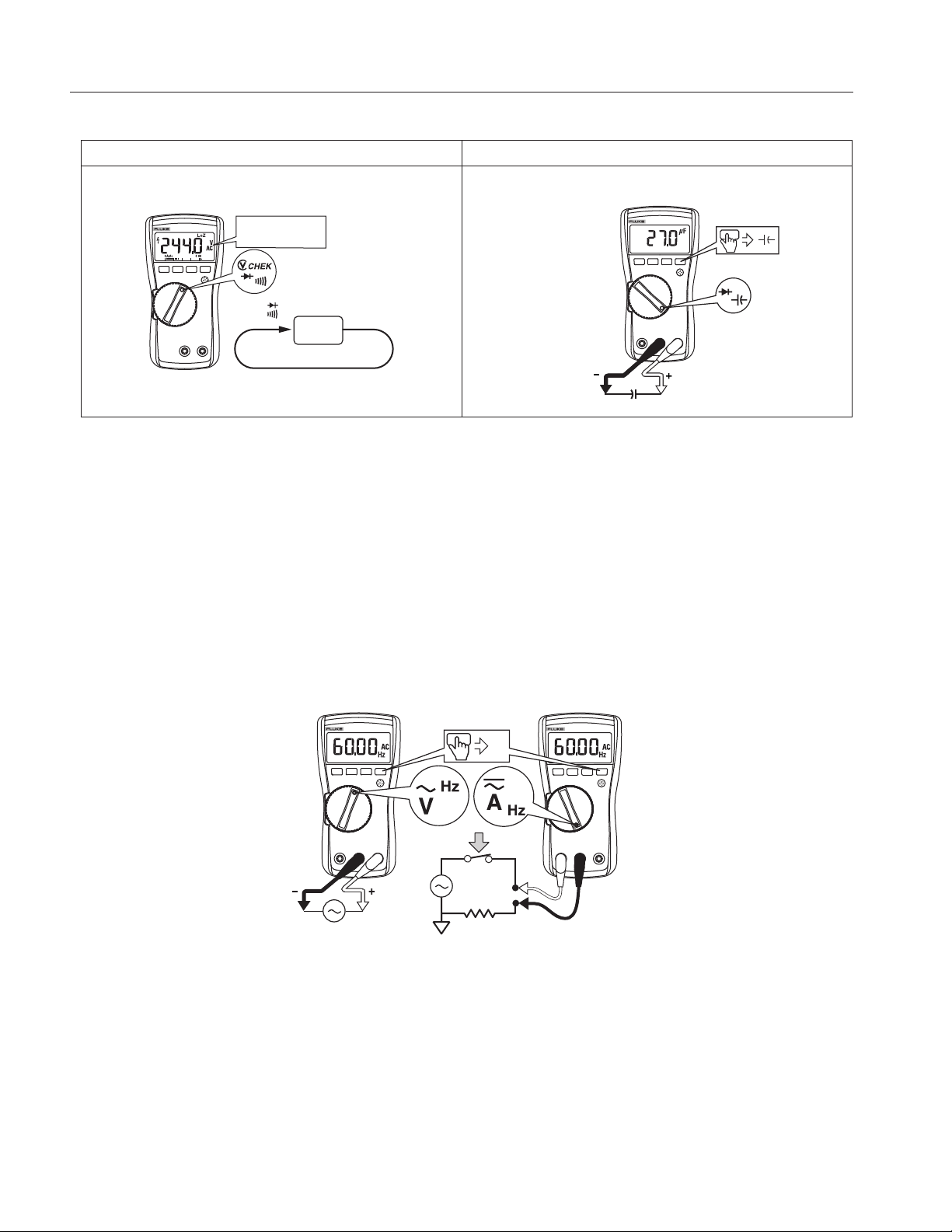
Measuring Capacitance (113, 115, 117) .................................................... 10
Measuring Frequency (115, 117) ............................................................... 10
Detecting AC Voltage Presence (117)........................................................ 11
Making Low Impedance Capacitance Measurements (115, 117) .............. 11
Testing Diodes (113, 115, 117) .................................................................. 12
Using the Bargraph.......................................................................................... 12
Maintenance ......................................................................................................... 13
Testing the Fuse (115, 117)............................................................................. 13
Replacing the Battery and Fuse ...................................................................... 13
Cleaning........................................................................................................... 14
Specifications........................................................................................................ 15
i
Page 4

110/113/114/115/117
Users Manual
ii
Page 5

Introduction
The Fluke Model 110, Model 113, Model 114, Model 115, and Model 117 (the Meter or Product) are batterypowered, true-rms multimeters with a 6000-count display and a bar graph. This manual applies to all models. All
figures show the Model 117 unless indicated.
How to Contact Fluke
To contact Fluke, call one of the following telephone numbers:
• Technical Support USA: 1-800-44-FLUKE (1-800-443-5853)
• Calibration/Repair USA: 1-888-99-FLUKE (1-888-993-5853)
• Canada: 1-800-36-FLUKE (1-800-363-5853)
• Europe: +31 402-675-200
• Japan: +81-3-6714-3114
• Singapore: +65-6799-5566
• China: +86-400-921-0835
• Brazil: +55-11-3530-8901
• Anywhere in the world: +1-425-446-5500
Or, visit Fluke's website at www.fluke.com
To register your product, visit http://register.fluke.com
To view, print, or download the latest manual supplement, visit http://us.fluke.com/usen/support/manuals
To request a printed manual, visit www.fluke.com/productinfo
.
.
.
.
Safety Information
For Product safety information, see the printed 110/113/114/115/117 Safety Information included with the
Product or located on the Fluke website.
Unsafe Voltage
To alert you to the presence of a potentially hazardous voltage, the Z symbol is displayed when the Meter
measures a voltage ≥30 V or a voltage overload (OL) condition. When making frequency measurements >1 kHz,
the Z symbol is unspecified.
Test Lead Alert
XW Warning
Personal injury or damage to the Meter can occur if you attempt to make a measurement with a
lead in an incorrect terminal.
To remind you to check that the test leads are in the correct terminals, LEAd is briefly displayed and an audible
beep sounds when you move the rotary switch to or from any A (Amps) position.
1
Page 6
110/113/114/115/117
Users Manual
Product Familiarization
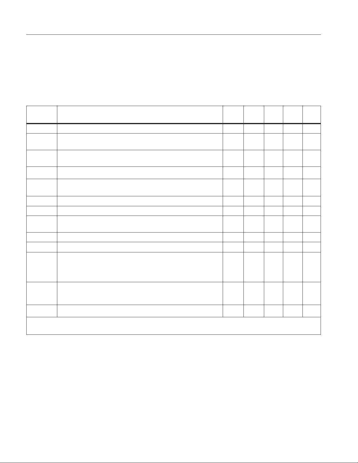
The manual explains features for multiple models. Because models have different features, not all of the
information in the manual may apply to your Meter. Use Table 1 to identify the features of your Meter.
Features
Table 1 is a list of the features for each Meter.
Table 1. Features
Switch
Position
OFF The Meter is turned off. zzzzz
x
e
D
l
Ω Ohms from 0.1 Ω to 40 MΩ. zzzzz
s Continuity beeper turns on at <20 Ω and turns off at >250 Ω. zzzzz
k CHEK
R Diode Test. Displays OL above 2.0 V. zzz
S Farads from 1 nF to 9999 μF. zzz
j
I
Automatically selects ac or dc volts based on the sensed input
with a low impedance input.
AC voltage from 0.06 V to 600 V.
Frequency from 5 Hz to 100 kHz.
DC voltage from 0.001 V to 600 V. zzzz
AC voltage from 6.0 to 600 mV, dc-coupled.
DC voltage from 0.1 to 600 mV.
LoZ low impedance measurement function to simultaneously
test for voltage or continuity.
AC current from 0.1 A to 10 A (>10 to 20 A, 30 seconds on,
10 minutes off). >10.00 A display flashes. >20 A, OL is
displayed. DC-coupled.
Frequency from 45 Hz to 5 kHz.
DC current from 0.001 A to 10 A (>10 A to 20 A, 30 seconds
on, 10 minutes off). >10.00 A display flashes. >20 A, OL is
displayed.
Measurement Function 110 113 114 115 117
zz
zzzz
zzzz
z
zz
zz
w
Note: All ac functions and Auto-V LoZ are true-rms. AC voltage is ac-coupled. Auto-V LoZ, AC mV and
2
Non-contact sensing of ac voltage. z
AC amps are dc-coupled.
Page 7
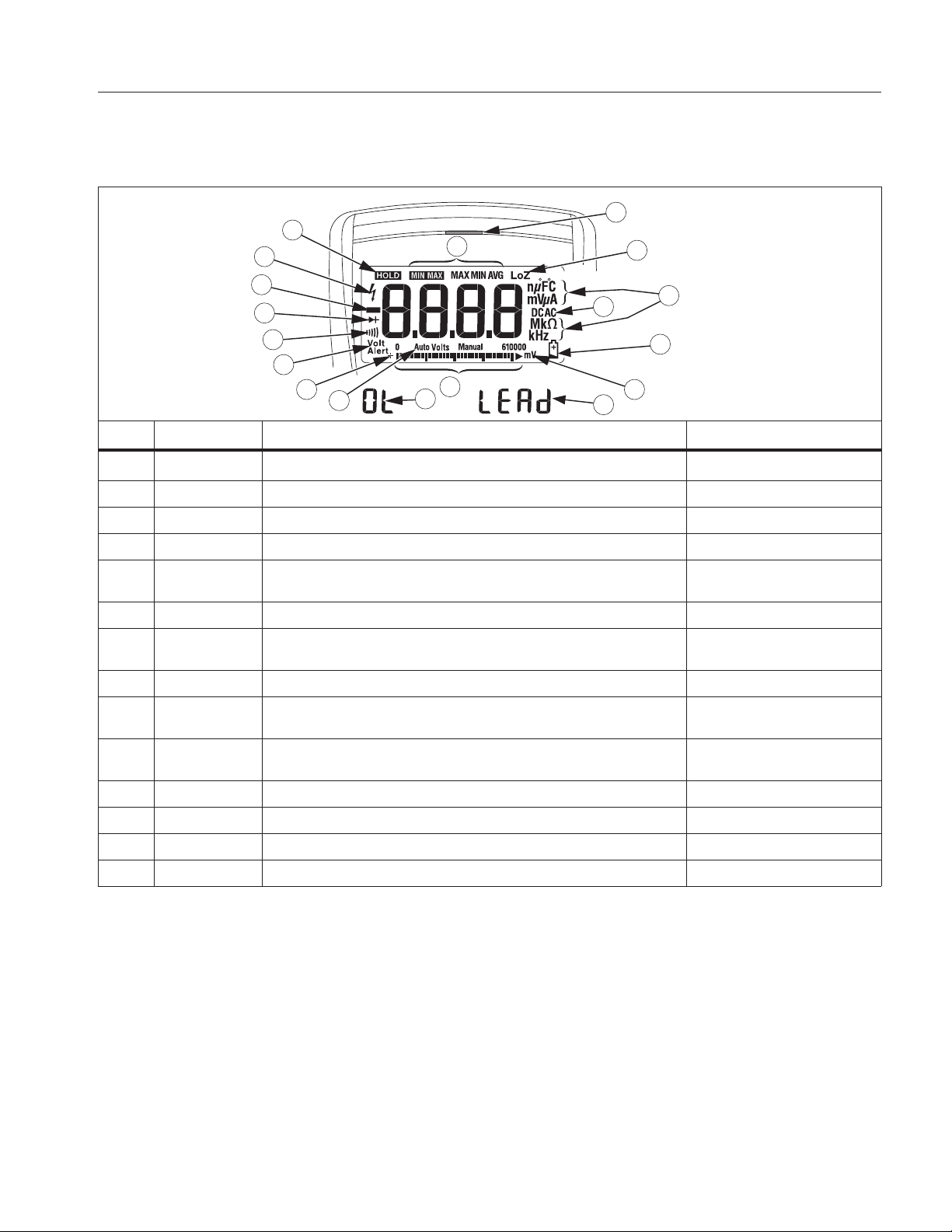
Display
Table 2 is a list of the features for each display.
True-rms Multimeter
Product Familiarization
Table 2. Display
11
18
8
9
10
12
13
17
VoltAlert
7
14
6
5
4
3
2
1
16
15
No. Symbol Meaning Model
w
s The Meter function is set to Continuity. 110, 113, 114, 115, 117
R The Meter function is set to Diode Test 113, 115, 117
O Input is a negative value. 110, 113, 114, 115, 117
Z
K Display hold enabled. Display freezes present reading. 110, 113, 114, 115, 117
M
VWX
(Red LED) Voltage presence through the non-contact VoltAlert sensor 117
LoZ
nμF mV μA
MkΩ kHz
DC AC Direct current or alternating current 110, 113, 114, 115, 117
N Battery low warning. 110, 113, 114, 115, 117
610000 mV Indicates the Meter’s range selection. 110, 114, 115, 117
(Bar graph) Analog display. 110, 113, 114, 115, 117
The Meter is in the VoltAlert™ non-contact voltage detect mode. 117
X Unsafe voltage. Measured input voltage ≥30 V, or voltage
overload condition (OL).
MIN MAX AVG mode enabled.
Maximum, minimum, average or present reading displays
The Meter is measuring voltage or capacitance with a low input
impedance.
Measurement units. 110, 114, 115, 117
110, 113, 114, 115, 117
110, 113, 114, 115, 117
113,114, 115, 117
3
Page 8
110/113/114/115/117
Users Manual
Table 2. Display (cont.)
No. Symbol Meaning Model
Auto Volts The Meter is in the Auto Volts function. 114, 117
Auto Autoranging. The Meter selects the range for best resolution. 110, 113, 114, 115, 117
Manual Manual ranging. User sets the Meter’s range. 110, 113, 114, 115, 117
+ Bar graph polarity 110, 113, 114, 115, 117
0L W The input is too large for the selected range. 110, 113, 114, 115, 117
LEAd
W Test lead alert. Briefly displayed whenever the Meter’s function
switch is rotated to or from any A position.
115, 117
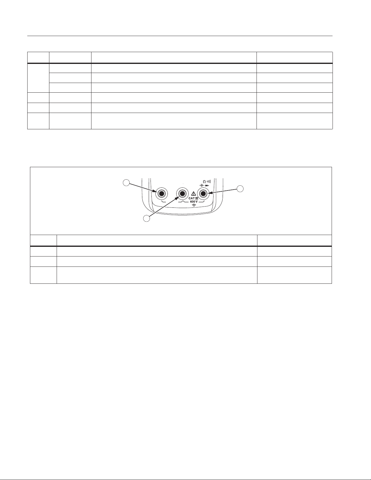
Terminals
Table 3 is a list of terminals on the Meter.
Table 3. Terminals
1
A
COM
10 A
FUSED
2
V
3
No. Description Model
Input terminal for measuring ac and dc current to 10 A. 115, 117
Common (return) terminal for all measurements. 110, 113, 114, 115, 117
Input terminal for measuring voltage, continuity, resistance, capacitance,
frequency and testing diodes.
110, 113, 114, 115, 117
4
Page 9
True-rms Multimeter
Product Familiarization
Error Messages
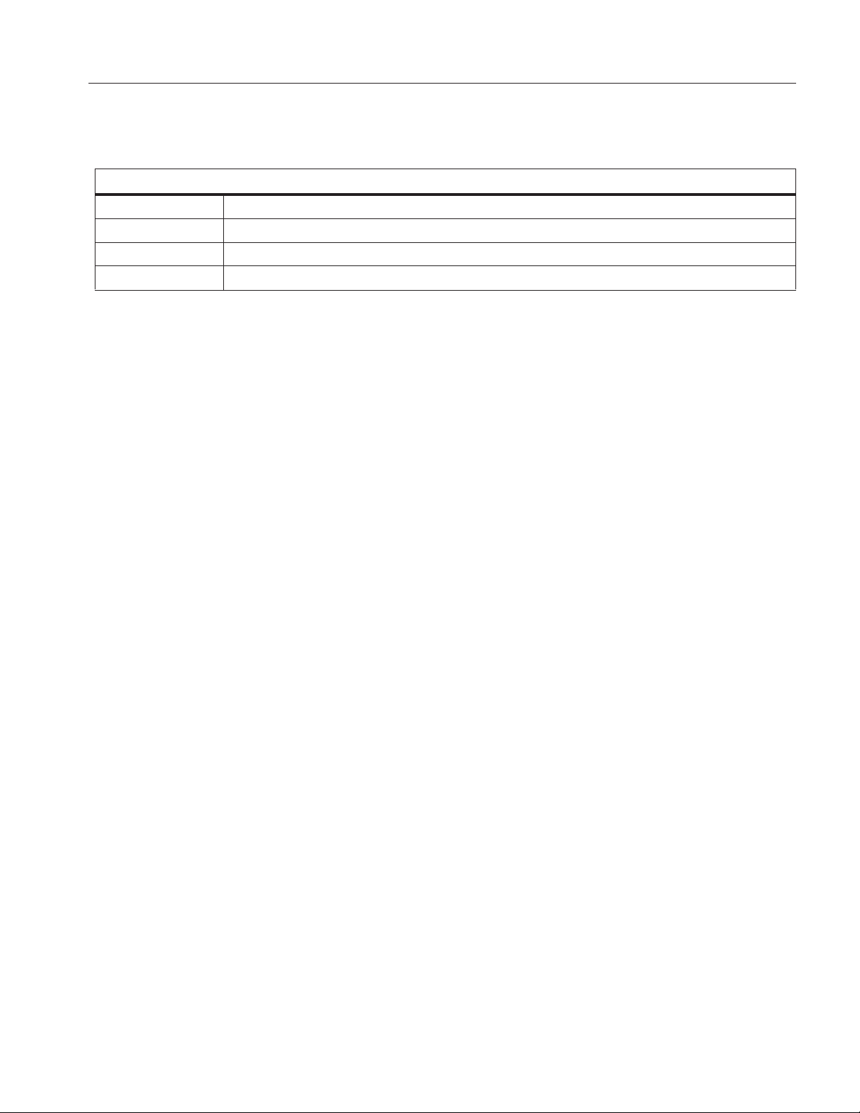
Table 4 is a list of error messages for the Meter.
Table 4. Error Messages
Error Messages
bAtt Battery must be replaced before the Meter will operate.
CAL Err Calibration required. Meter calibration is required before the Meter will operate.
EEPr Err Internal error. The Meter must be repaired before it will operate.
F11- Err Internal error. The Meter must be repaired before it will operate.
Battery Saver™ (Sleep Mode)
If the Meter is ON, but inactive and not connected to voltage for more than 20 minutes, the display goes blank to
save battery life.To use the Meter, press any button or turn the rotary switch. To disable the Sleep mode, see
Power-Up Options. The Sleep mode is always disabled in the MIN MAX AVG mode.
MIN MAX AVG Recording Mode
The MIN MAX AVG recording mode captures the minimum and maximum input values (ignoring overloads), and
calculates a running average of all readings. When the Meter detects a new high or low, the Meter beeps.
Note
Autoranging and Battery Saver™ are disabled in MIN MAX AVG mode.
1. Select the measurement function and range.
2. Push p to enter MIN MAX AVG mode.
M and MAX show on the display. The highest reading detected since entering MIN MAX AVG shows
on the display.
3. Push p to step through the low (MIN), average (AVG), and present readings.
4. To pause MIN MAX AVG recording without erasing stored values, push f. (K shows on the display.)
5. To resume MIN MAX AVG recording, push f again.
6. To exit and erase stored readings, push p for at least one second, or turn the rotary switch.
5
Page 10

110/113/114/115/117
Users Manual
Display HOLD
XW Warning
To avoid electric shock, when Display HOLD is activated, be aware that the display will not
change when you apply a different voltage.
In the Display HOLD mode, the Meter freezes the display.
1. Push f to activate Display HOLD. (K shows on the display.)
2. To exit and return to normal operation, push f or turn the rotary switch.
Backlight
Push Q to toggle the backlight on and off.
The backlight automatically turns off after 40 seconds. To disable backlight auto-off, see Power-Up Options.
Manual and Autoranging
The Meter has both Manual and Autorange modes. The Meter defaults to Autorange. To toggle between Manual
and Autorange, push
• In the Autorange mode, the Meter selects the range with the best resolution.
• In the Manual Range mode, you override Autorange and select the range yourself. Push
enter Manual range. (Manual shows on the display.) Push
range, the Meter wraps to the lowest range.
You cannot manually change the range in the MIN MAX AVG or Display HOLD modes. If you push
qwhile in MIN MAX AVG or Display Hold, the Meter beeps twice, indicating an invalid operation and
the range does not change.
qfor 1 second.
qfor 1 second to
qto increment the range. After the highest
Note
Power-Up Options
To select a Power-Up Option, hold down the button indicated in Table 5 while turning the Meter from OFF to any
other function. Power-Up Options are canceled when you turn off the Meter and when sleep mode is activated.
Table 5. Power-Up Options
Button Power-Up Options
f
p
Turns on all display segments until button is released.
Disables beeper. bEEP shows when enabled.
113 - Turns on all display segments until button is released.
q
115, 117 - Enables low impedance capacitance measurements. LCAP shows when enabled.
g
Q
Disables Battery Saver™ (Sleep mode). PoFF shows when enabled.
Disables auto backlight off. LoFF is displayed when enabled.
6
Page 11
True-rms Multimeter
600
6
60
RANGE
RANGE
600 kΩ
6 kΩ
60 kΩ
600 kΩ
6 MΩ
40 MΩ
Open Short
Open
Closed
Open
Closed
Product Familiarization
Making Basic Measurements
When connecting the test leads to the circuit or device, connect the common (COM) test lead before connecting
the live lead; when removing the test leads, remove the live lead before removing the common test lead.
XW Warning
To avoid electric shock, injury, or damage to the Meter, disconnect circuit power and discharge
all high-voltage capacitors before testing resistance, continuity, diodes, or capacitance.
Measuring Resistance
113 110, 114, 115, 117
Testing for Continuity
Use the continuity function as a fast, convenient method to check for opens and shorts. For maximum
accuracy in making resistance measurements, use the Meter’s resistance (e) function.
113 110, 114, 115,117
Note
7
Page 12
110/113/114/115/117
AC for AC Voltage
DC for DC Voltage
60 V6 V 600 V
RANGE
Volts AC
Volts DC
DC
Millivolts AC
Millivolts DC
Users Manual
Measuring AC and DC Voltage
113 110, 114, 115,117
V
Using Auto Volts Selection (114, 117)
With the function switch in the x position, the Meter automatically selects a dc or ac voltage measurement
based on the input applied between the V or + and COM jacks.
This function also sets the Meter’s input impedance to approximately 3 kΩ to reduce the possibility of false
readings due to ghost voltages.
Measuring AC and DC Millivolts (110, 114, 115, 117)
With the function switch in the l position, the Meter measures ac plus dc millivolts. Press g to set the
Meter to dc millivolts.
8
Page 13
True-rms Multimeter
Product Familiarization
Measuring AC or DC Current (115, 117)
XW Warning
To avoid personal injury or damage to the Meter:
• Never attempt to make an in-circuit current measurement when the open-circuit potential to
earth is >600 V.
• Check the Meter's fuse before testing. See Testing the Fuse (115, 117).
• Use the proper terminals, switch position, and range for your measurement.
• Never place the probes in parallel with a circuit or component when the leads are plugged into
the A (Amps) terminals.
To measure current:
1. Turn circuit power off.
2. Break the circuit
3. Insert the Meter in series with the circuit, and then turn circuit power on.
1
A
2 3
Measuring Current above 10 Amps (110, 114, 115, 117)
The millivolt and voltage function of the Meter can be used with an optional mV/A output Current Probe to
measure currents that exceed the rating of the Meter. Make sure the Meter has the correct function selected, AC
or DC, for your current probe. Refer to a Fluke catalog or contact your local Fluke representative for compatible
current clamps.
9
Page 14
110/113/114/115/117
Z
AC for AC Voltage
DC for DC Voltage
60 V6 V 600 V
RANGE
Users Manual
Measuring Capacitance (113, 115, 117)
113 115,117
AC for AC Voltage
DC for DC Voltage
Measuring Frequency (115, 117)
XW Warning
To avoid electrical shock, disregard the bar graph for frequencies >1 kHz. If the frequency of the
measured signal is >1 kHz, the bar graph and
The Meter measures the frequency of a signal by counting the number of times the signal crosses a trigger level
each second. The trigger level is 0 V, 0 A for all ranges.
Press g to turn on or turn off the frequency measurement function on and off. Frequency works with ac
functions only.
In frequency, the bar graph and range annunciator indicate the ac voltage or current present.
Select progressively lower ranges using manual ranging for a stable reading.
are unspecified.
AC Voltage Frequency
AC Current Frequency
VoltAlert
Hz
10
Page 15
True-rms Multimeter
VoltAlert
VoltAlert
Lo
RANGE
VoltAlert
Product Familiarization
Detecting AC Voltage Presence (117)
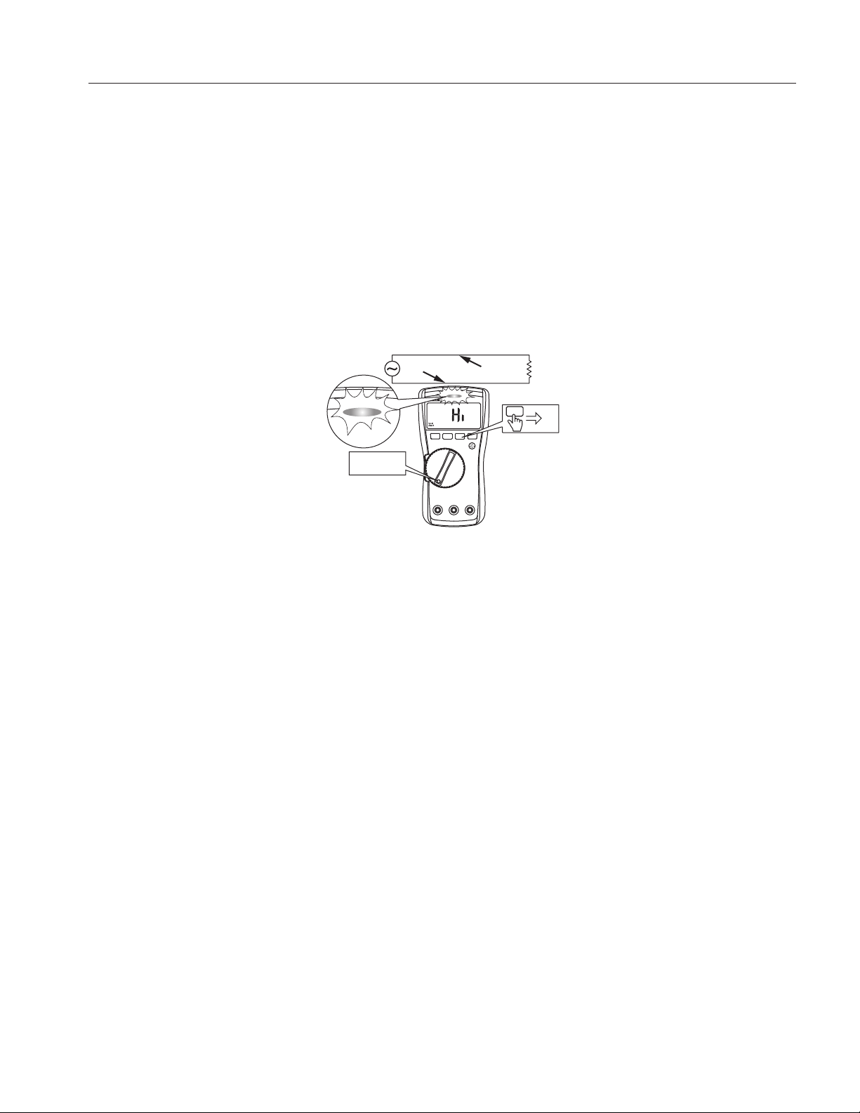
To detect the presence of ac voltage, place the top of the Meter close to a conductor. The Meter gives an audible
as well as visual indication when voltage is detected. The sensitivity settings are:
• Lo: use on flush mounted wall sockets, power strips, flush mounted industrial outlets and various power
cords.
• Hi: for ac voltage detection on other styles of recessed power connectors or sockets where the actual ac
voltage is recessed within the connector itself.
The VoltAlert detector works in bare wire applications with voltages as low as 24 V in the Hi setting.
XW Warning
If there is no indication, voltage could still be present. Do not rely on the VoltAlert detector with
shielded wire. Operation may be effected by differences in socket design, insulation thickness
and type.
Hot
Neutral
Making Low Impedance Capacitance Measurements (115, 117)
For making capacitance measurements on cables with ghost voltage:
1. Hold q as you turn on the Meter to enable the low-input impedance Capacitance mode.
2. Wait until
In this mode, capacitance measurements will have a lower accuracy and lower dynamic range.
This setting is not saved when the Meter is turned off or goes into sleep mode.
LCAP shows on the display.
Note
11
Page 16
110/113/114/115/117
Forward Bias
Single
Beep
Reverse Bias
Good Diode Good Diode
Good DiodeGood Diode
Forward Bias
Reverse Bias
Shorted
and
Open
Bad Diode Bad Diode
Bad Diode
Bad Diode
Open
Shorted
and
1x
Good DiodeGood Diode
Forward Bias
Reverse Bias
Bad Diode
Bad Diode
Open
Shorted
and
Users Manual
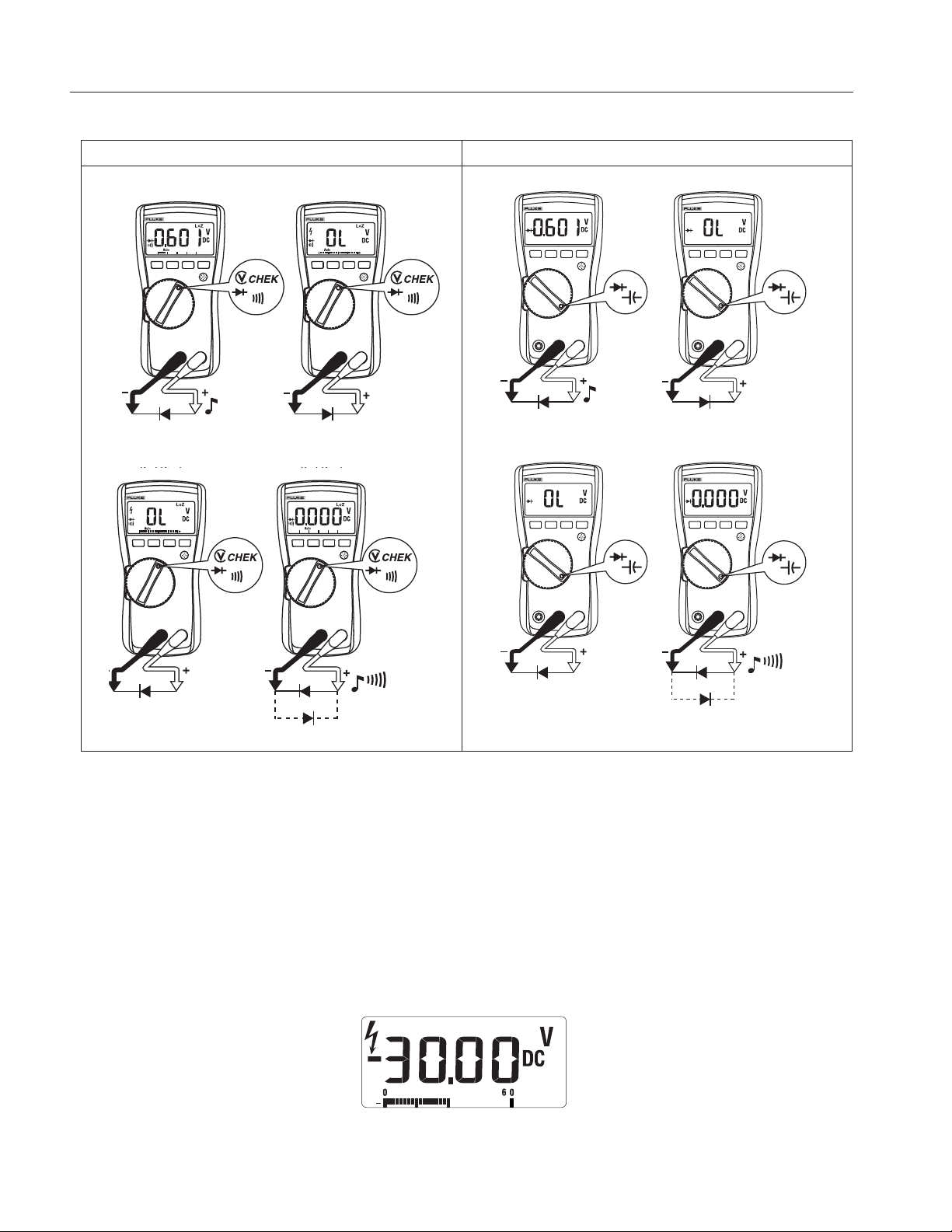
Testing Diodes (113, 115, 117)
113 115, 117
Using the Bargraph
The bar graph is like the needle on an analog meter. It has an overload indicator ( ) to the right and a polarity
indicator (+) to the left.
Because the bar graph is much faster than the digital display, the bar graph is useful for making peak and null
adjustments.
The bar graph is disabled when measuring capacitance. In frequency, the bar graph and range annunciator
indicates the underlying voltage or current up to 1 kHz.
The number of segments indicates the measured value and is relative to the full-scale value of the selected
range.
In the 60 V range, for example (see below), the major divisions on the scale represent 0, 15, 30, 45, and 60 V. An
input of -30 V turns on the negative sign and the segments up to the middle of the scale.
12
Page 17
True-rms Multimeter
Maintenance
Maintenance of the Meter consists of battery and fuse replacement, as well as case cleaning.
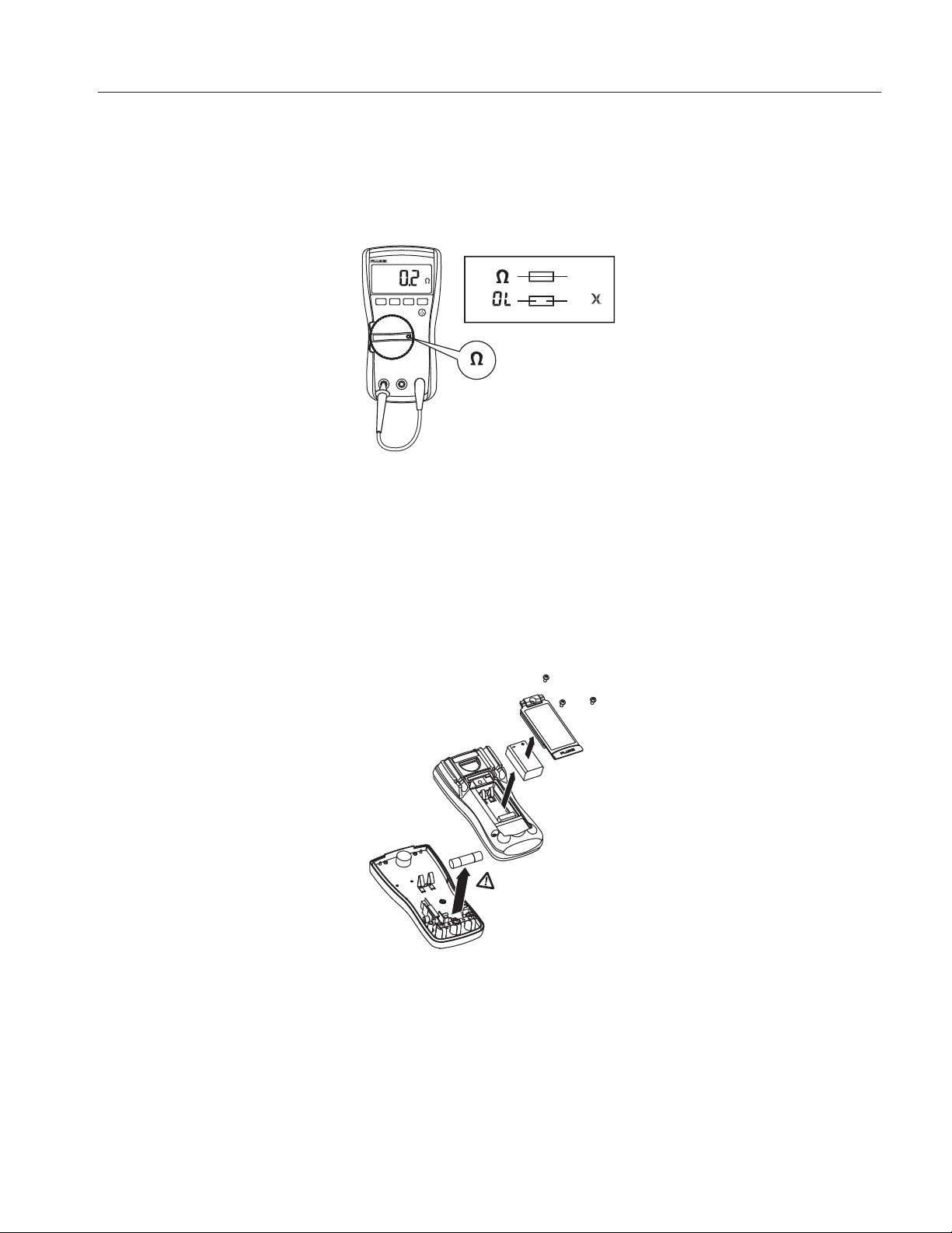
Testing the Fuse (115, 117)
Test fuse as shown in Figure 1.
Maintenance
<.5
Figure 1. Test the Fuse
OK
OK
Replacing the Battery and Fuse
XW Warning
To avoid shock, injury, or damage to the Meter:
• Remove test leads from the Meter before opening the case or battery door.
• Use ONLY a fuse with the amperage, interrupt voltage, and speed ratings specified.
See Figure 2 for disassembly.
Figure 2. Disassembly
13
Page 18

110/113/114/115/117
Users Manual
To remove the battery door for battery replacement:
1. Remove the test leads from the Meter.
2. Remove the battery door screw.
3. Use the finger recess to lift the door slightly.
4. Lift the door straight up to separate it from the case.
5. The battery fits inside the battery door, which is then inserted into the case, bottom edge first, until it is fully
seated. Do not attempt to install the battery directly into the case.
6. Install and tighten battery door screw.
To open the case for fuse replacement:
1. Remove the test leads from the Meter.
2. Remove the Meter from its holster.
3. Remove two screws from the case bottom.
4. Separate the case bottom from the case top.
5. Remove the fuse from its holder and replace it with an 11 A, 1000 V, FAST fuse having a minimum interrupt
rating of 17,000 A. Use only Fluke PN 803293.
6. To re-assemble the Meter, first attach the case bottom to the case top, then install the two screws. Finally,
insert the Meter into its holster.
Cleaning
Wipe the case with a damp cloth and mild detergent. Dirt or moisture in the terminals can affect readings.
14
Page 19

True-rms Multimeter
Specifications
Specifications
Accuracy is specified for 1 year after calibration, at operating temperatures of 18 °C to 28 °C, with relative humidity at 0 % to 90 %.
Extended specifications are available at www.Fluke.com.
Maximum voltage between any
terminal and earth ground ........................................600 V
W Fuse for A input (115 & 117 only)........................ 11 A, 1000 V, IR 17 kA
Display
Digital........................................................................ 6000 counts, updates 4/s
Bar Graph .................................................................33 segments, updates 32/s
Temperature
Operating.................................................................. -10 °C to 50 °C
Storage .....................................................................-40 °C to 60 °C
Temperature Coefficient............................................ 0.1 x (specified accuracy)/°C (<18 °C or >28 °C)
Altitude
Operating.................................................................. 2000 meters
Storage .....................................................................10 000 meters
Relative Humidity....................................................... 95 % to 30 °C, 75 % to 40 °C, 45 % to 50 °C
Battery......................................................................... IEC 6LR61
Battery Life
113............................................................................ Alkaline: 300 hours typical, without backlight
110, 114, 115, 117.................................................... Alkaline: 400 hours typical, without backlight
Safety ..........................................................................IEC 61010-1: Pollution Degree 2
IEC 61010-2-033
113............................................................................ Measurement CAT IV 600 V
110, 114.................................................................... Measurement CAT III 600 V
115, 117.................................................................... Measurement CAT III 600 V, 10 A
Ingress Protection .....................................................IEC 60529: IP42 (non-operating)
Electromagnetic Compatibility (EMC)
International.............................................................. IEC 61326-1: Portable Electromagnetic Environment
Group 1: Equipment has intentionally generated and/or uses conductively-coupled radio frequency energy that is necessary for the
internal function of the equipment itself.
Class A: Equipment is suitable for use in all establishments other than domestic and those directly connected to a low-voltage
power supply network that supplies buildings used for domestic purposes. There may be potential difficulties in ensuring
electromagnetic compatibility in other environments due to conducted and radiated disturbances.
Caution: This equipment is not intended for use in residential environments and may not provide adequate protection to radio
reception in such environments.
Emissions that exceed the levels required by CISPR 11 can occur when the equipment is connected to a test object.
Korea (KCC) .............................................................Class A Equipment (Industrial Broadcasting & Communication Equipment)
Class A: Equipment meets requirements for industrial electromagnetic wave equipment and the seller or user should take notice of
it. This equipment is intended for use in business environments and not to be used in homes.
USA (FCC) ............................................................... 47 CFR 15 subpart B. This product is considered an exempt device per clause 15.103.
CISPR 11: Group 1, Class A
15
Page 20
110/113/114/115/117
Users Manual
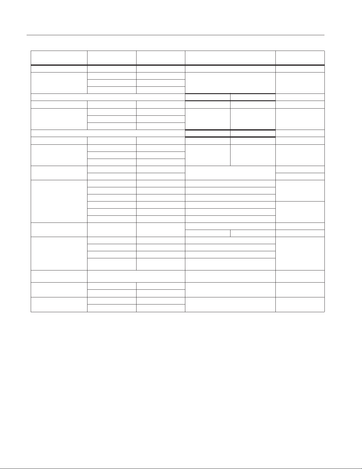
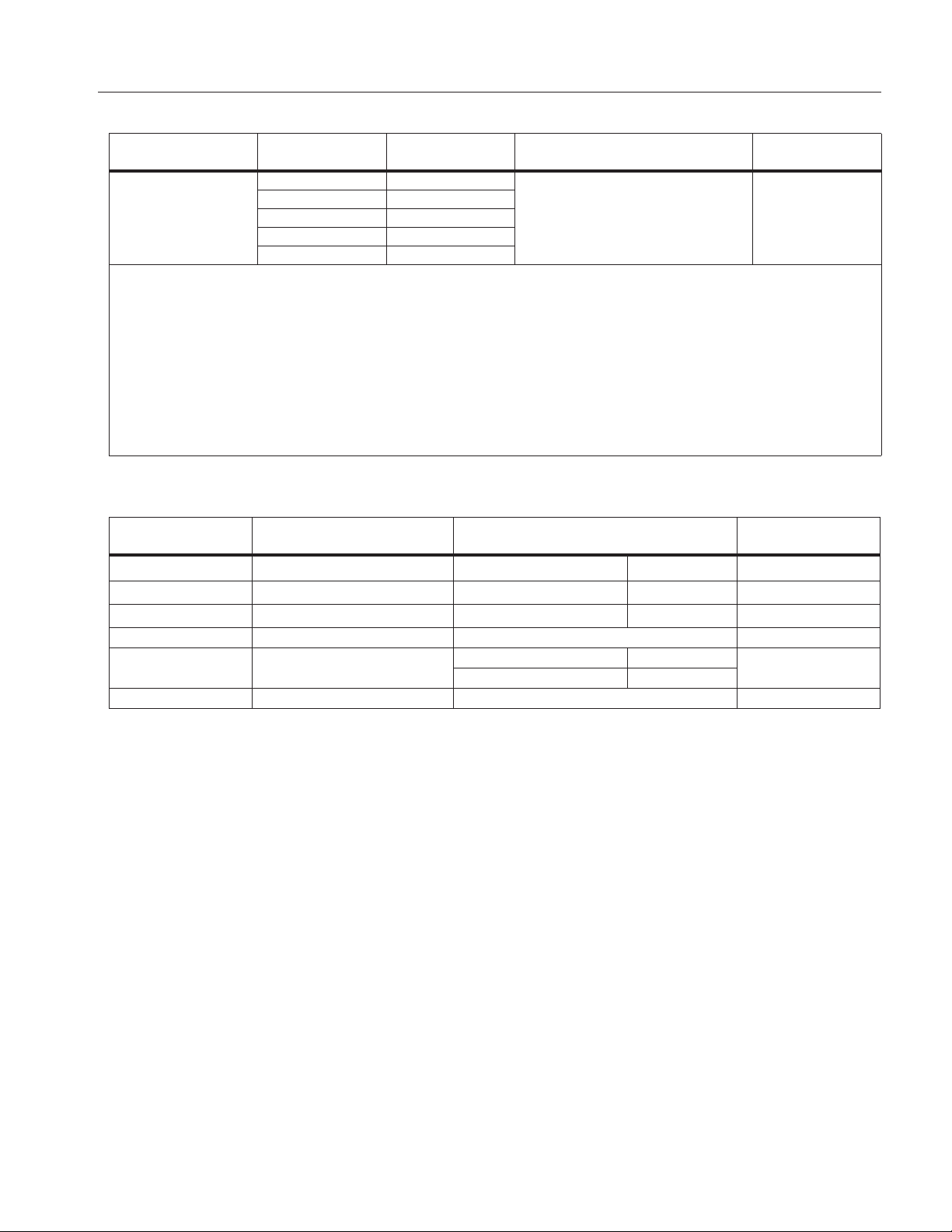
Table 6. Accuracy Specifications
Function Range Resolution
± ([% of Reading] + [Counts])
DC Millivolts 600.0 mV 0.1 mV 0.5 % + 2 110, 114, 115, 117
6.000 V 0.001 V
DC Volts
0.5 % + 2 110, 114, 115, 11760.00 V 0.01 V
600.0 V 0.1 V
DC, 45 to 500 Hz 500 Hz to 1 kHz
Auto-V LoZ
[1]
True-rms
600.0 V 0.1 V 2.0 % + 3 4.0 % + 3 114, 117
6.000 V 0.001 V
k CHEK
[4]
2.0 % + 3 4.0 % + 3 11360.00 V 0.01 V
600.0 V 0.1 V
45 to 500 Hz 500 Hz to 1 kHz
AC millivolts
[1]
True-rms
600.0 mV 0.1 mV 1.0 % + 3 2.0 % + 3 110, 114, 115, 117
6.000 V 0.001 V
AC Volts
[1]
True-rms
1.0 % + 3 2.0 % + 3 110, 114, 115, 11760.00 V 0.01 V
600.0 V 0.1 V
Continuity
[5]
600 Ω 1 Ω
--- --- 113
Beeper on <20 Ω, off >250 Ω. Detects
opens or shorts of 500 μs or longer.
600.0 Ω 0.1 Ω 0.9 % + 2
6.000 kΩ 0.001 kΩ 0.9 % + 1
Ohms
[5]
60.00 kΩ 0.01 kΩ 0.9 % + 1
600.0 kΩ 0.1 kΩ 0.9 % + 1
6.000 0Ω 0.001 MΩ 0.9 % + 1
40.00 MΩ 0.01 MΩ 5.0 % + 2
Diode Test
[5]
2.000 V 0.001 V
0.9 % + 2 115, 117
2.0 % + 3 113
1000 nF 1 nF 1.9 % + 2
Capacitance
[5]
Lo-Z Capacitance
(Power-up option)
AC Amps True-rms
(45 Hz to 500 Hz)
DC Amps
10.00 μF0.01 μF1.9 % + 2
100.0 μF0.1 μF1.9 % + 2
9999 μF1 μF
100 μF - 1000 μF: 1.9 % +2
>1000 μF: 5 % + 20
1 nF to 500 μF 10 % + 2 typical 115, 117
[1]
6.000 A 0.001 A
10.00 A
[3]
0.01 A
6.000 A 0.001 A
10.00 A
[3]
0.01 A
1.5 % + 3 115, 117
1.0 % + 3 115, 117
Accuracy
Model
110, 114, 115, 117
110, 113, 114, 115,
117
110, 114, 115, 117
113, 115, 117
16
Page 21
True-rms Multimeter
Specifications
Table 6. Accuracy Specifications (cont.)
Function Range Resolution
99.99 Hz 0.01 Hz
Hz (V or A input)
Notes:
[1] All ac ranges except Auto-V LoZ are specified from 1 % to 100 % of range. Auto-V LoZ is specified from 0.0 V. Because inputs below 1 % of range are not
specified, it is normal for this and other true-rms meters to display non-zero readings when the test leads are disconnected from a circuit or are shorted
together. For volts, crest factor of 3 at 4000 counts, decreasing linearly to 1.5 at full scale. For amps, crest factor of 3. AC volts is ac-coupled.
Auto-V LoZ, AC mV, and AC amps are dc-coupled.
[2] AC Volts Hz is ac-coupled and specified from 5 Hz to 99.99 kHz. Minimum input required above 50.00 kHz typically is >1.1 vac sine. Minimum input typical
and not specified. AC Amps Hz is dc-coupled and specified from 45 Hz to 5 kHz.
[3] W>10 A unspecified.Duty cycle: >10 A to 20 A, 30 seconds on, 10 minutes off.
[4] 113 only: All
normal for this and other true-rms meters to display non-zero readings when the test leads are disconnected from a circuit or are shorted together. Crest
factor of 3 at 4000 counts, decreasing linearly to 1.5 at full scale.
[5] 113 only: After measuring voltage, a wait time of 1 minute is required to maintain accuracy of ohms, capacitance, diode test, and continuity.
[2]
k CHEK voltage ranges are specified from 60 counts to 100 % of range. Because inputs <60 counts are not specified, it is possible and
999.9 Hz 0.1 Hz
9.999 kHz 0.001 kHz
50.00 kHz 0.01 kHz
99.99 kHz 0.01 kHz
± ([% of Reading] + [Counts])
0.1 % + 2 115, 117
Accuracy
Model
Table 7. Input Characteristics (110, 114, 115, 117)
Function Input Impedance (Nominal)
Volts AC >5 MΩ <100 pF >60 dB at dc, 50 or 60 Hz 0.5 % + 2
Volts DC >10 MΩ <100 pF >100 dB at dc, 50 or 60 Hz 0.5 % + 2
Auto-V LoZ ~3 kΩ <500 pF >60 dB at dc, 50 or 60 Hz
Open Circuit Test Voltage Full Scale Voltage Short Circuit Current
Ohms <2.7 V dc
Diode Test <2.7 V dc 2.000 V dc <1.2 mA
Common Mode Rejection Ratio
(1 kΩ Unbalanced)
to 6.0 MΩ 40 MΩ
<0.7 V dc <0.9 V dc
Normal Mode
Rejection
- - -
- - -
- - -
<350 μA
17
Page 22
110/113/114/115/117
Users Manual
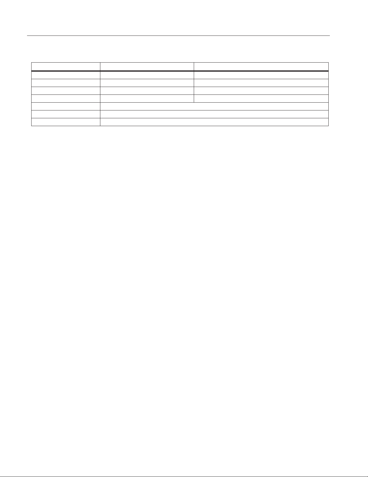
Table 8. Input Characteristics (113)
Function Input Impedance (Nominal) Common Mode Rejection Ratio
k CHEK ~3 kΩ <300 pF >60 dB at dc, 50 or 60 Hz
Open Circuit Test Voltage Full Scale Voltage
Ohms <2.7 V dc <0.7 V dc
Diode Test <2.7 V dc <2.000 V dc
Short Circuit Current
Ohms <350 μA
Diode Test <1.0 mA
MIN MAX Recording Accuracy and Response Time (113)
Specified accuracy of the measurement function ±40 counts in k CHEK for changes >500 ms in duration, ±12 counts in e for changes
>325 ms in duration. Typical 100 ms response to 80 %. Response time not specified for capacitance.
18
 Loading...