

Page 1
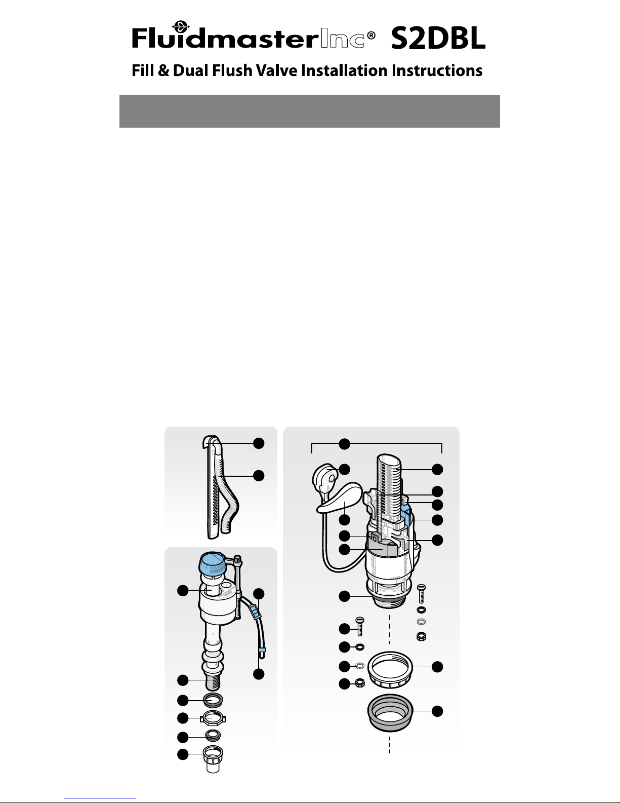
Q
S
T
R
U
V
Z
C
B
L
M
N
H
I
J
A
E
O
F
P
G
K
D
D
W
X
Y
N.
O.
P.
Q.
R.
S.
T.
U.
V.
W.
X.
Y.
Z.
Release clip
Flush valve lock nut
Rubber gasket
Fill valve
Threaded shank
Shank washer
Lock nut
Cone washer
Water supply line
Rell mount
Corrugated tube
Roller clamp
Rell tube &
locking clamp
PARTS LIST
A.
B.
C.
D.
E.
F.
G.
H.
I.
J.
K.
L.
M.
Flush valve
Lever mounting base
Flush handle assembly
Grey/Blue oat stop
Grey oat (Full Flush)
Flush valve washer
Bolt
Rubber washer
Brass washer
Brass nut
Overow tube
Rail
Blue oat (Half Flush)
www.uidmaster.com 1
Overview
READ ENTIRE INSTRUCTIONS BEFORE STARTING INSTALLATION
Page 2
4
2
1
3
1
2
3
1.6
1.4
1.5
1.7
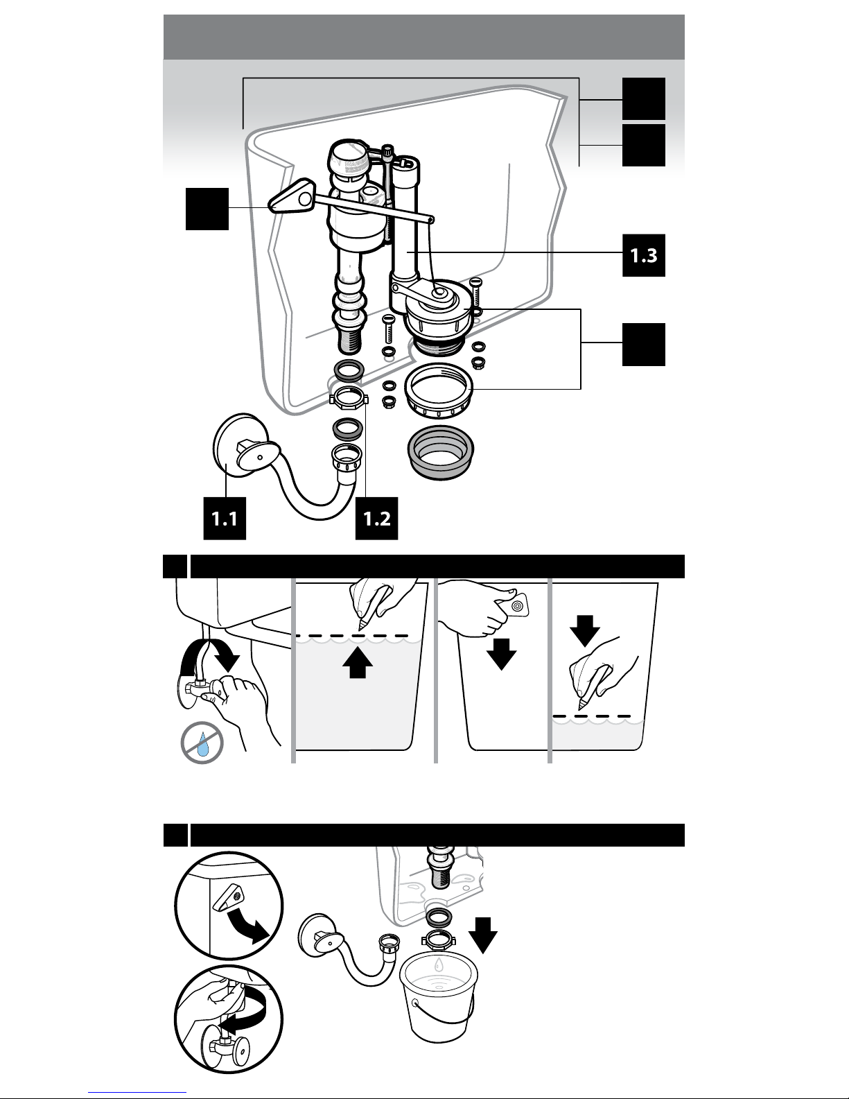
(2) Remove tank top.
Mark existing
water level inside.
(3) Flush tank a
single time.
(4) Mark a line at the
residual water level
inside.
(1) Press and hold lever to
drain water. Remove excess
water with sponge.
(2) Disconnect supply line.
(3) Place bucket underneath ll valve shank. Use
Channel Locks® to loosen
and remove lock-nut from
ll valve shank. Allow water
to drain into bucket.
(1) Turn o
water supply.
www.uidmaster.com2
Step 1: Remove old parts
1.2
1.1
Prepare
Remove ll valve
Page 3
3
1
2
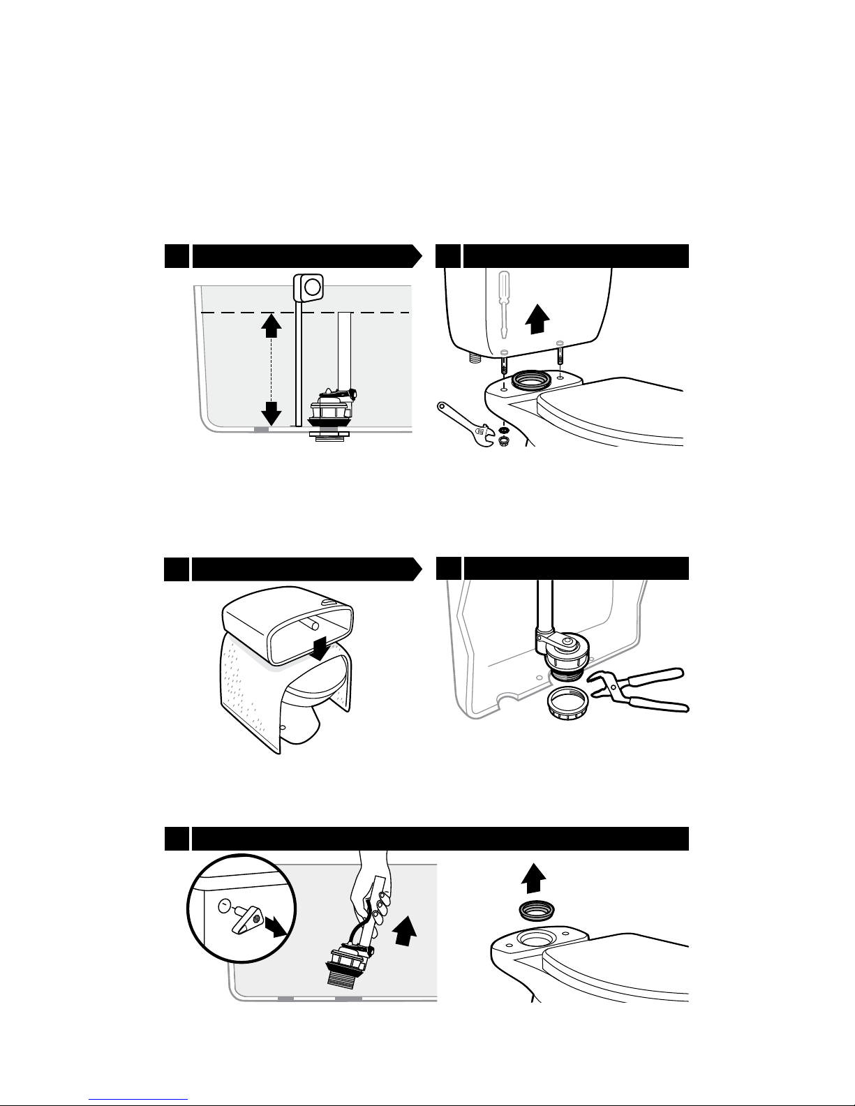
Use Channel Locks® to loosen and
remove ush valve nut.
Cover the toilet seat with a towel. Place
the tank horizontally on top of the towel.
This will protect both surfaces.
(1) Remove ush valve. (2) Loosen and remove lever nut (lever nut is reverse threaded).
(3) Remove old gasket.
NOTE: SAVE the existing parts until installation is complete.
Measure and record distance of old ush
valve from bottom of tank to top of the
overow tube.
Use screw driver to loosen nuts in
tank. Use crescent wrench to loosen if
the nut is too tight. Remove tank from
bowl.
www.uidmaster.com 3
Measure ush valve
1.6
Remove lock nuts
1.3 1.4 Remove tank
Place tank on seat
1.5
1.7
Remove old parts
Page 4
O
2.5
F
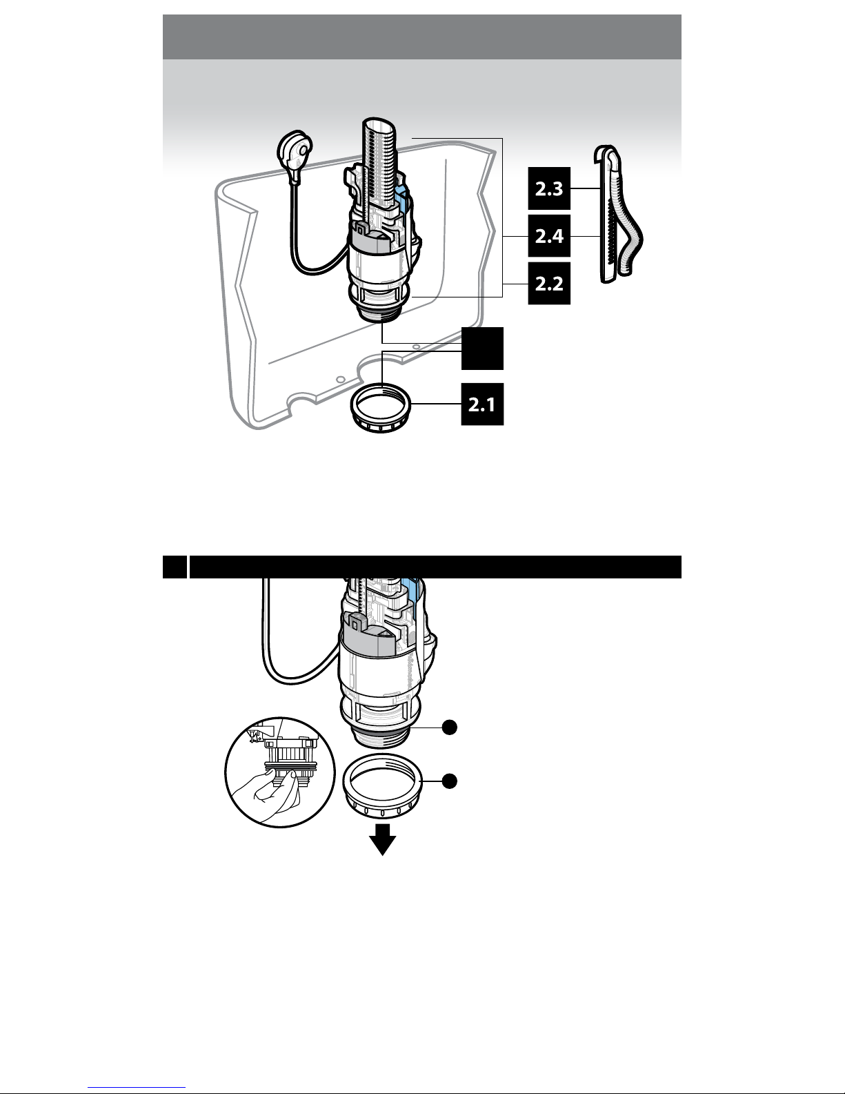
Remove ush valve lock nut (O) from
base of Dual Flush Valve assembly. Make
sure ush valve washer (F) stays in place.
www.uidmaster.com
4
Step 2: Install Flush Valve
2.1 Prepare ush valve
Page 5

W
W
X
O
8
1
N
2
1
A
K
3
K
18
17
16
15
14
13
12
11
10
9
8
7
6
5
4
3
2
1
18
17
16
15
14
13
12
11
10
9
8
7
6
2
Place Dual Flush Valve (A) in tank
ensuring washer is seated fully onto
shank of Dual Flush Valve. Match height
of new overow tube (K) on Dual Flush
Valve with recorded measurement from
step 1.3.
Remove Dual Flush Valve from tank.
(1) Press inward on release clip (N) and
(2) remove rell mount (W).
(1) Cut the excess overow tube (K) with
a saw at measurement taken in step 1.3.
NOTE: DO NOT cut below segment 2.
(2) Insert rell mount (W) ensuring it is
low enough to t inside the tank and
clears the lid, but high enough to allow
a minimum of 2” clearance between the
top of the overow tube and the top of
the rell mount.
(3) Cut corrugated rell hose (X) if
necessary.
NOTE: DO NOT cut lever attachment.
Place ush valve in tank. Install ush
valve lock nut (O) to ush valve
threaded shank and hand-tighten.
Flush valve should remain in same
position after nut is tightened.
NOTE: Hand tighten only.
www.uidmaster.com
5
2.2 2.3Measure
Remove rell mount
2.4 Cut to size Install in tank2.5
2” minimum
Page 6
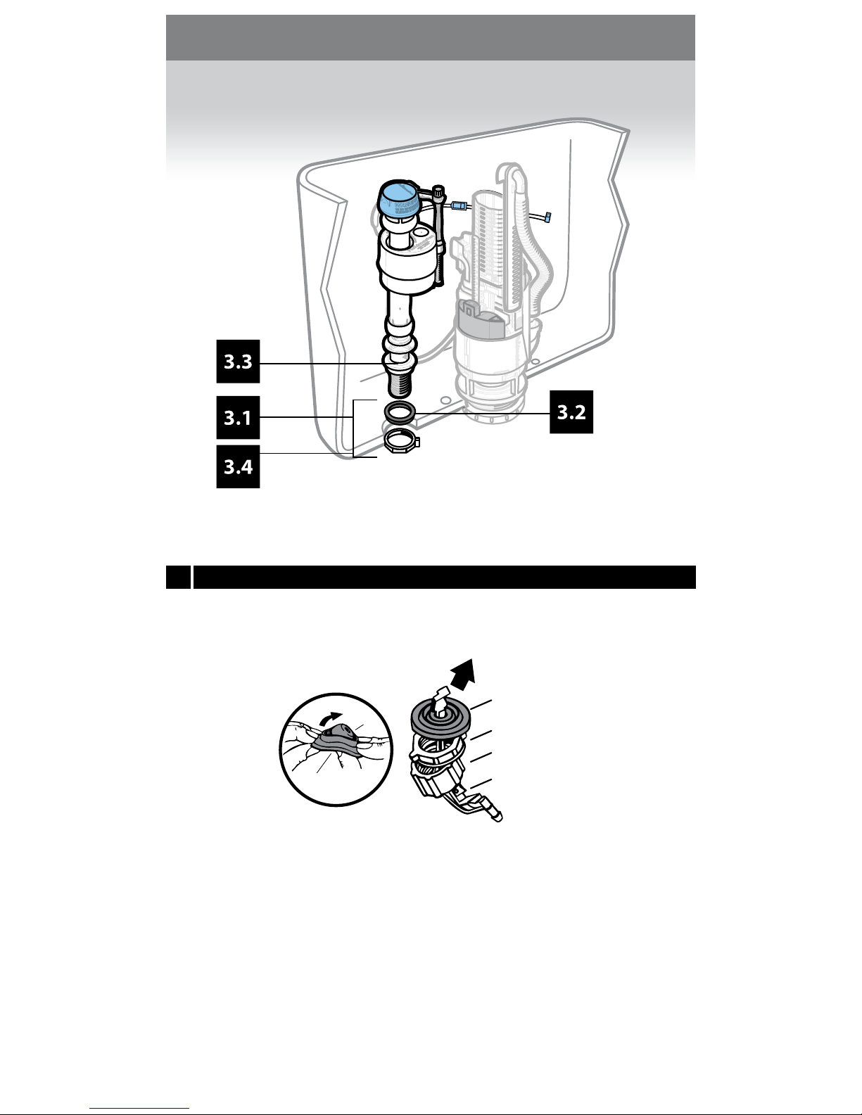
COUPLING NUT
SHANK AND
CONE WASHER
LOCK NUT
ANGLE ADAPTER
CONE
WASHER
SHANK
WASHER
Disassemble small parts - carefully separate cone washer from
center of shank washer. Lock nut and shank washer are required
for ll valve installation; cone washer and coupling nut for water
supply connection. The angle adapter will not be needed for this
installation.
NOTE: There are several union types, please refer to identication
chart at end of instruction manual.
www.uidmaster.com
6
Step 3: Install ll valve
3.1 Prepare
Page 7
2
T
3”
1
S
Locking
ring
1
2
3
18
17
16
15
14
13
12
11
10
9
8
7
6
18
17
16
15
14
13
12
11
10
9
8
7
6
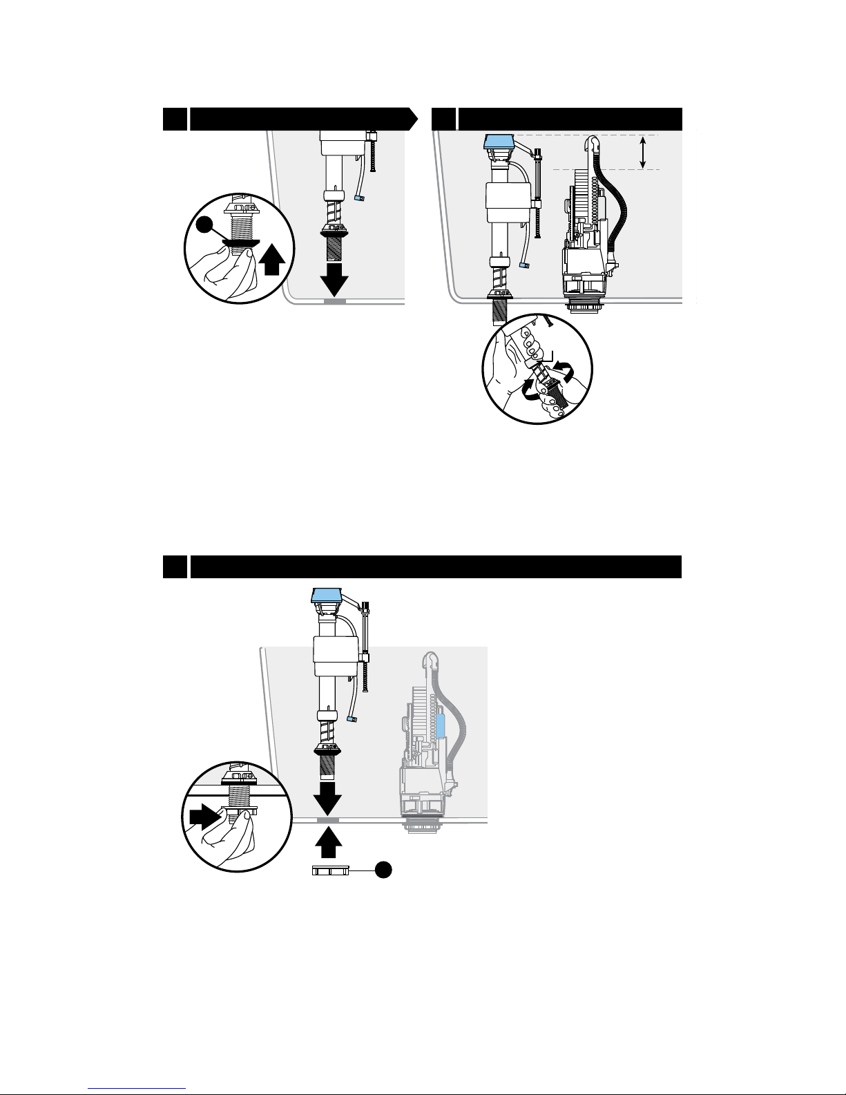
(1) Put shank washer (S), onto ll valve
shank and (2) place ll valve in tank.
Check height of the ll valve. It must be
approximately 3” higher than the
overow tube. Adjust by twisting the
threaded shank in or out.
NOTE: DO NOT move the locking ring
to adjust shank.
(1) Place ll valve in tank.
(2) Fasten ll valve lock nut (T) to shank
(3) hand tighten.
NOTE: DO NOT over-tighten.
www.uidmaster.com
7
3.2 Reconnect 3.3 Adjust
Install3.4
Page 8
1
Z
4.4
P
18
17
16
15
14
13
12
11
10
9
8
7
6
H
G
I
J
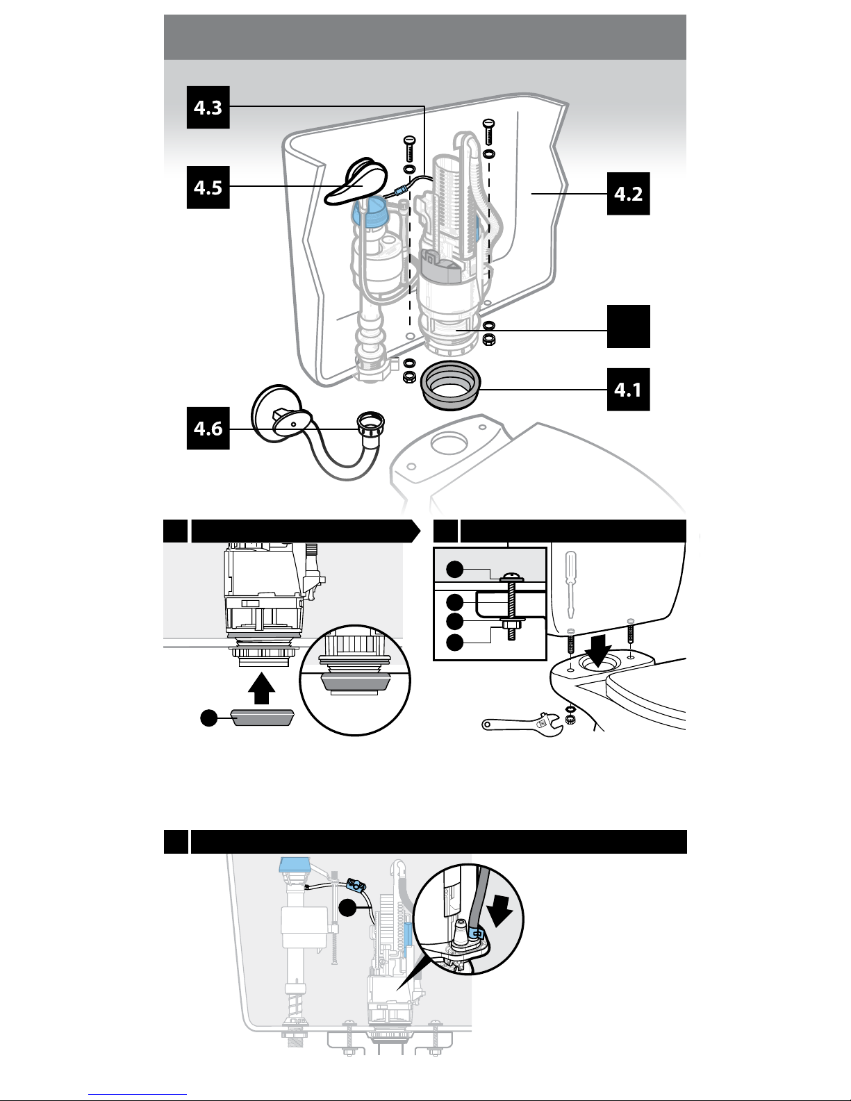
Important: Attach the
end of rell hose to
nipple on Dual Flush
Valve as shown in
picture. Make sure both
tubes are clear of ll
valve and ush valve
operation. Ensure hose
clamp is secure.
Slide rubber gasket (P) onto threaded
end of ush valve. Use old gasket if
supplied new gasket does not t.
Secure tank to bowl with bolts (G), rubber
washers (H) brass washers (I) and hex nut (J).
Tank should be level after it has been installed.
NOTE: DO NOT over-tighten. May break tank.
Nut will not be used with all toilets.
www.uidmaster.com
8
4.3
Step 4: Reassemble
Secure rell hose
4.1 4.2
Prepare
Replace
Page 9
FULL
HALF
FULL
HALF
1
Reverse threads
B
A
1
2
1
1
1
V
2
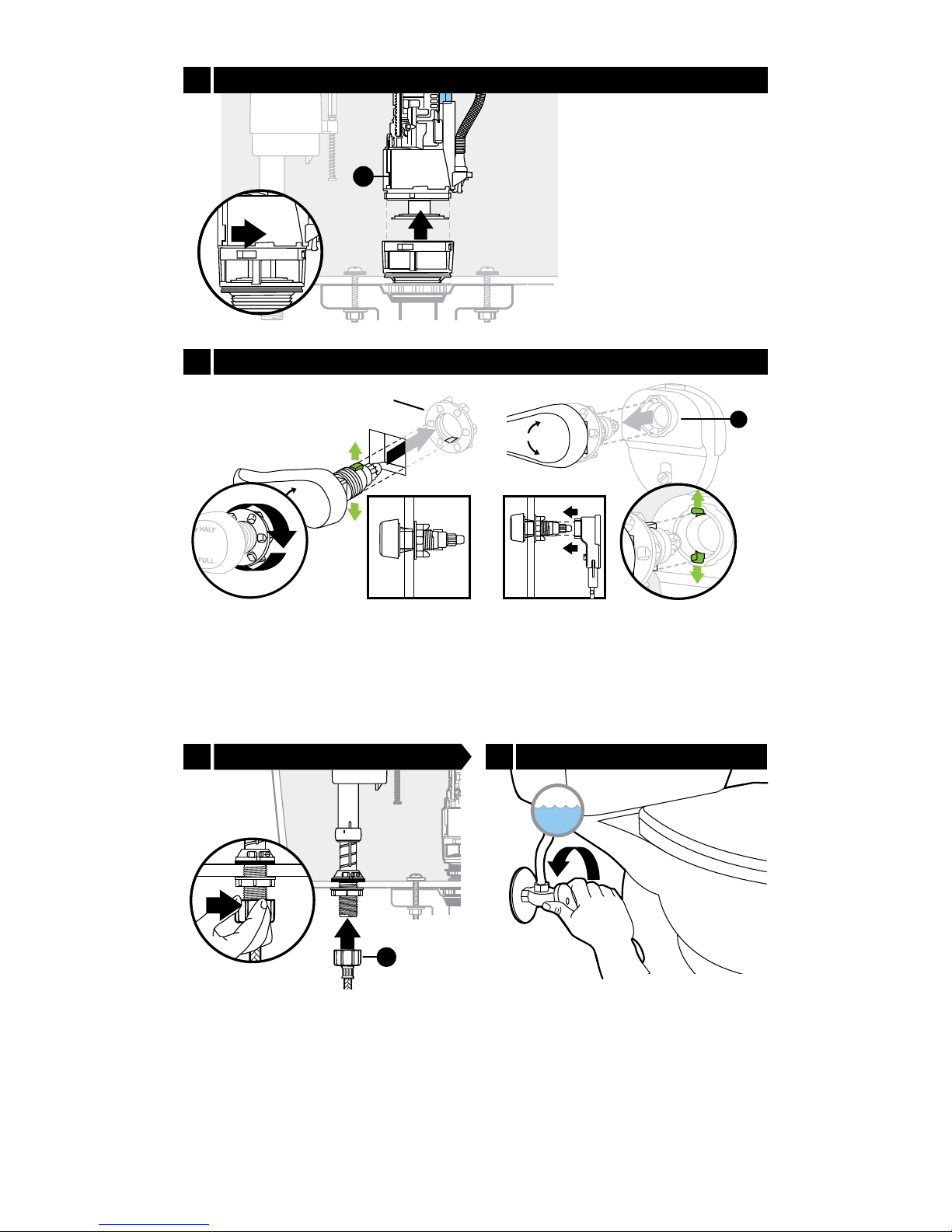
Attach handle lever to tank and handtighten lever lock-nut.
Note: Nut is reverse threaded. Make sure
tabs on collar are oriented vertically.
Line up tabs on lever into the slots on
lever mounting base (B) and snap into
base. Tabs on lever shank need to be
installed vertically.
(1) Reconnect water supply line (V). Use
Step 3.1 chart (on pg. 13) to determine
the appropriate assembly parts required
to properly reconnect the water supply.
NOTE: Hand tighten only. DO NOT use
thread lubricants. Use of thread sealants
or lubricants can damage plastic nut
and result in ooding and property
damage.
If you need to adjust the
orientation of the ush
valve (A), release from
base by (1) turning
counterclockwise until
tabs unlock. (2) Lift
valve out and
adjust/orient as needed.
Turn on water supply. Check for leaks.
www.uidmaster.com
9
4.5 Install handle
4.4 Rotate (if necessary)
4.6 Reconnect 4.7 Turn on water supply
Page 10
+
_
5.1
5.2
5.3
2
1
M
D
L
18
17
16
15
14
13
12
11
10
9
8
7
6
5
4
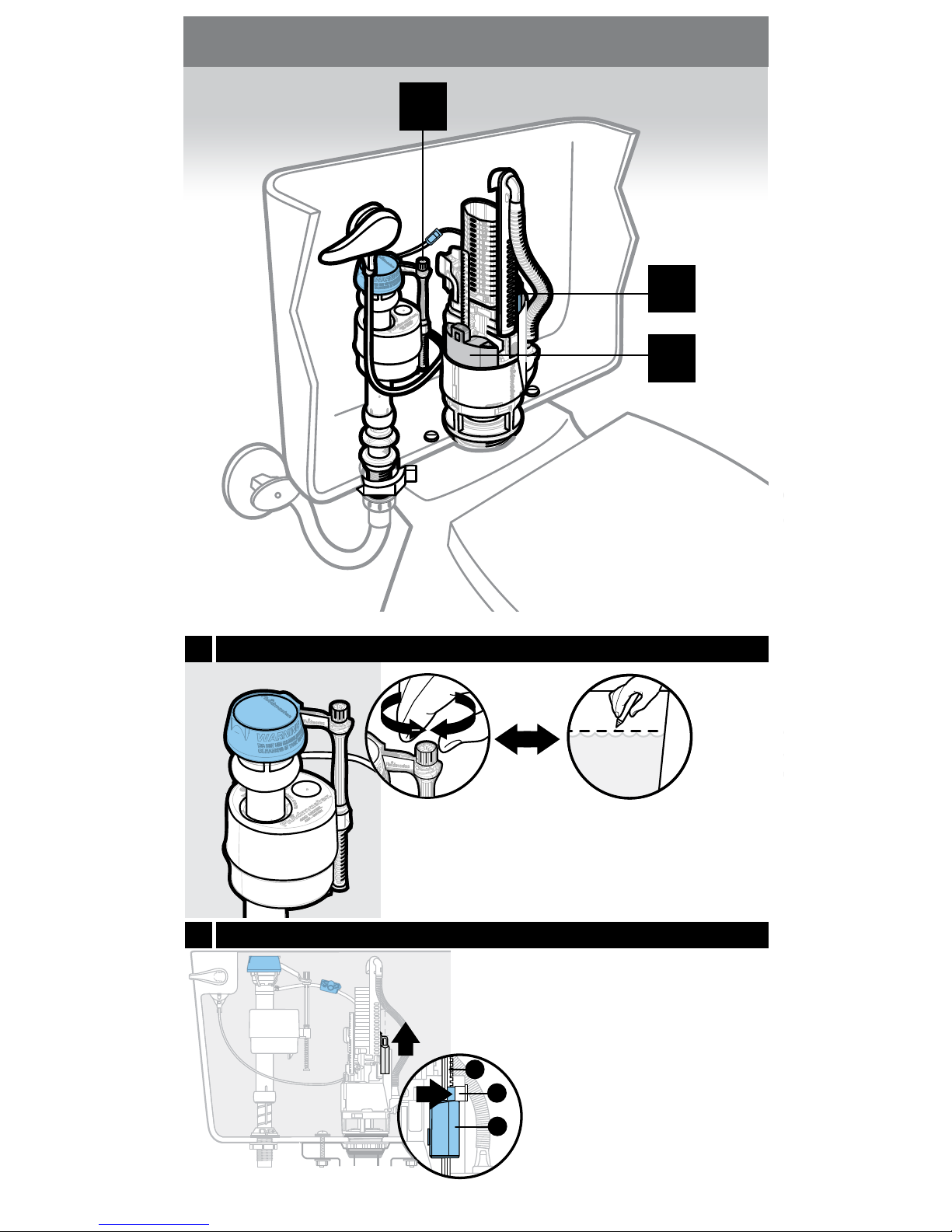
Compare water level after tank has lled with existing
line marked in step 1.1. The new ll valve comes with an
adjustment screw found at the end of oat control arm.
Turn screw clockwise to increase water level, and
counter-clockwise to decrease water level.
As marked
in step 1.1
The blue oat controls the
half ush.
(1) Pull out stop (D) on blue
oat (M).
(2) Raise blue oat (M) to the
TOP of the rail (L).
www.uidmaster.com
10
Step 5: Final adjustments
5.1 Fill valve adjustment
5.2
Adjust blue oat
Page 11
M
D
1
M
D
2
3
M
E
D
18
17
16
15
14
13
12
11
10
9
8
7
6
5
4
18
17
16
15
14
13
12
11
10
9
8
7
6
5
4
18
17
16
15
14
13
12
11
10
9
8
7
6
5
4
18
17
16
15
14
13
12
11
10
9
8
7
6
5
4
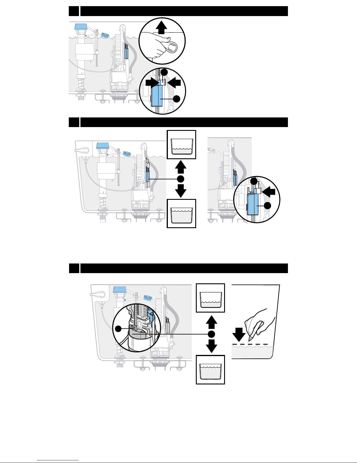
Engage the stop (D) to lock the
position of the blue oat (M).
The grey oat controls the full ush. Pull out stop (D) on grey oat (E).
Activate full ush by pushing lever down. If residual water after ush is lower
than line marked in step 1.1, raise grey oat and repeat. If residual water is
higher than line marked in step 1.1, lower grey oat and repeat.
You may be able to save water by moving grey oat upwards.
Test ush - put toilet paper in
bowl and (1) lift lever to ush
toilet. (2) Pull out stop (D) on
blue oat (M) and lower one
step. (3) Engage the stop (D) to
lock the position of the blue oat
(M). Wait for tank to rell before
retesting.
Lower the setting on blue oat (M) one step at a
time until the paper fully ushes. The higher the
blue oat, the more water you save.
www.uidmaster.com
11
5.3
5.2
Adjust blue oat (continued)
5.2
Adjust grey oat
Adjust blue oat (continued)
Page 12
Hose clamp
Hose clamp
Roller clamp
Z
Y
1
3
5
0
2
4
6
8
less water
0
2
4
6
8
more water
6
4
2
10 Min.
Y
Y
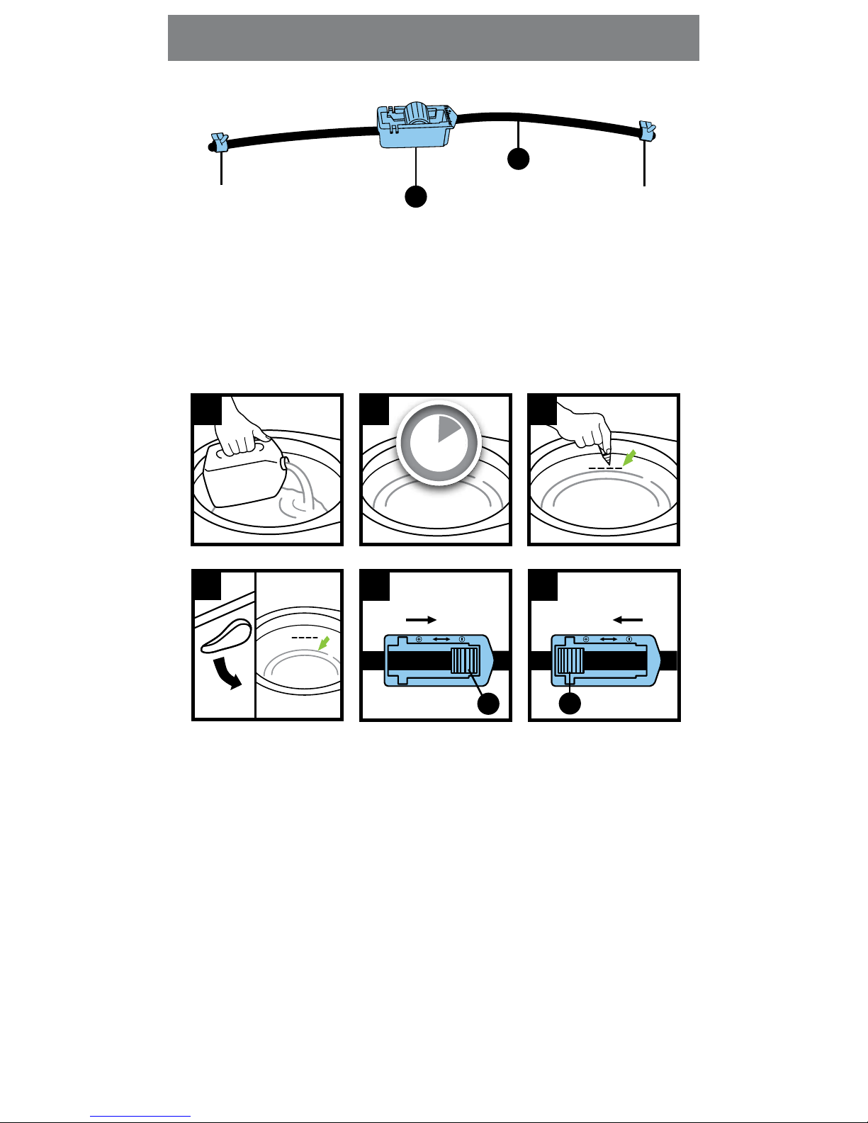
(1) Add a gallon of water to bowl.
(2) Wait 10 minutes, allowing water to settle.
(3) Mark water level with a wax pencil.
(4) Flush toilet.
a. If the water reaches your mark in the bowl and the ll valve is still
running, then decrease the water entering the bowl: See step (5).
b. If the valve shuts o before the water has reached your mark in the
bowl, then increase the water entering the bowl: See step (6).
(5) Push down on the roller (Y) and roll it to the next lower number. Repeat
step (4).
(6) Push down on the roller (Y) and roll it to the next higher number. Repeat
step (4).
Continue adjusting in this manner until the water reaches your mark in the
bowl at the same time the ll valve turns o in the tank.
The rell tube (Z) directs water into the ush valve and down into the bowl
during a ush. If too much water enters the bowl, it is wasted going over the
trap and down the drain. The roller clamp (Y) regulates the amount of water
entering the bowl.
www.uidmaster.com
12
Step 6: Fine tuning
Page 13
CONE
LOCK NUT
WASHER
WATER
SHUTOFF
FLAT
WASHER
COUPLIN G
NUT
LOCK NUT
COUPLIN G
NUT
LOCK NUT
COUPLIN G
NUT
COUPLIN G
NUT
WATER
SHUTOFF
SPIRA L
CONE
WASHER
WATER
SHUTOFF
WATER
SHUTOFF
BALL TUBING
METAL/COPPE R
FLARED TUBING
METAL FLANGED
TUBING
METAL SPIRAL
TUBING
VINYL/ BRAIDED
CONNECTOR
PLASTIC OR METAL
COMPRESSION
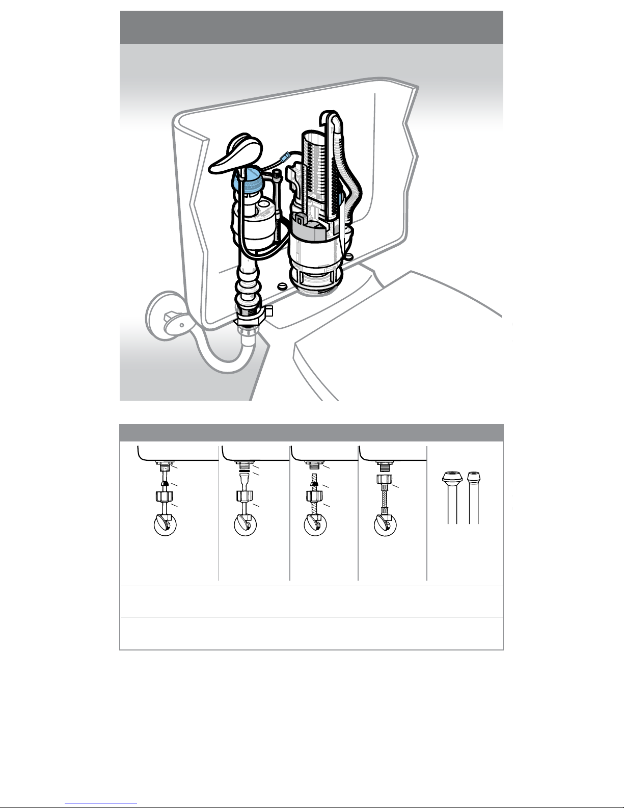
Use chart to determine the appropriate assembly parts required to properly reconnect the water supply.
DO NOT use plumber’s putty to seal these fittings (Teflon tape optional). Do not use thread lubricants. Use of thread sealants or
lubricants can damage plastic nut and result in flooding and property damage.
Use Fluidmaster coupling nut
and cone washer to replace
existing parts. Water supply
tube must extend 1/2 inch
inside threaded shank of valve.
Use existing coupling
nut and existing flat
washer.
Use existing spiral
cone washer.
Captive cone washer
already included.
No additional
washers required.
Do not use Fluidmaster's
coupling nut and the
cone washer on plastic or
metal tubing as shown.
CAUTION: DO NOT use CONE WASHER with PLASTIC SUPPLY LINE or METAL SPIRAL TUBING.
CAUTION: Locknut and coupling nut should be hand tightened only! Over tightening locknut or coupling nut could result in
breakage and flooding.
Go to our website at www.uidmaster.com for more information.
13
(Optional for Step 3.1) Identify union type
Completed installation
Page 14
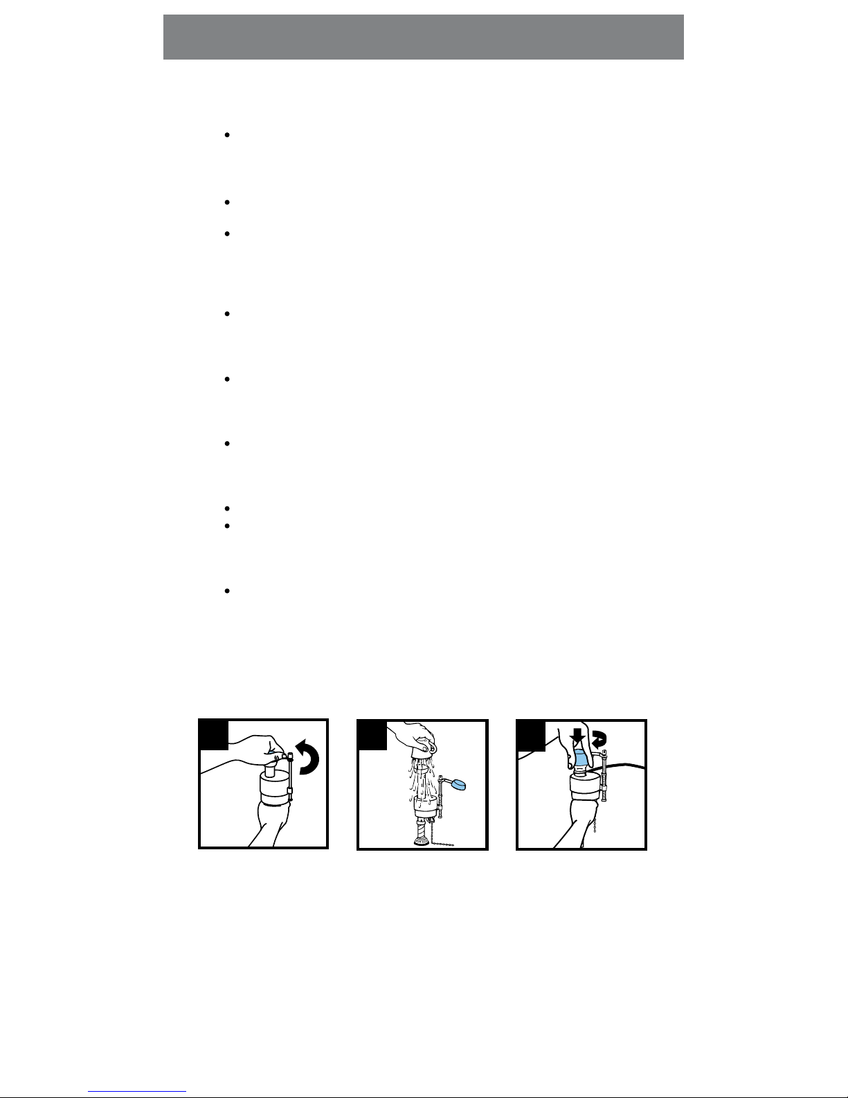
1 2 3
Remove cap assembly. Flush out valve. Hold
cup over valve. Turn on
water.
FLUSHING OUT DEBRIS
FILL VALVE WILL NOT TURN OFF
WATER LEVEL IN BOWL IS TOO LOW
Move roller clamp to higher number.
There may be debris at seal. Sand and rust move through water pipes.
Always clear debris from water lines. See “Flushing Out the Debris” below.
The seal inside the valve top may be damaged-replace with a genuine
Fluidmaster 242 seal.
FULL FLUSH WILL NOT ADEQUATELY REMOVE WASTE
Lower grey oat to allow more water to be ushed.
HALF FLUSH WILL NOT ADEQUATELY REMOVE WASTE
Lower blue oat to allow more water to be ushed.
SEAL LEAKING
Should dual ush valve leak, unclip valve from base, and re-align seal.
FULL FLUSH CLOSES IMMEDIATELY AFTER LEVER IS RELEASED
Top of rell mount should be set 2” above top of overow tube.
Raise rell mount higher. (see step 2.4)
OVERFLOW TUBE STICKS OPEN ON FULL & HALF FLUSH
Remove cable mount from Dual Flush assembly. Check lever cable for kinks.
Straighten by hand. If cable still sticks, replace cable.
Go to our website at www.uidmaster.com for more solutions to toilet problems.
Replace cap assembly.
14
Troubleshooting
Page 15
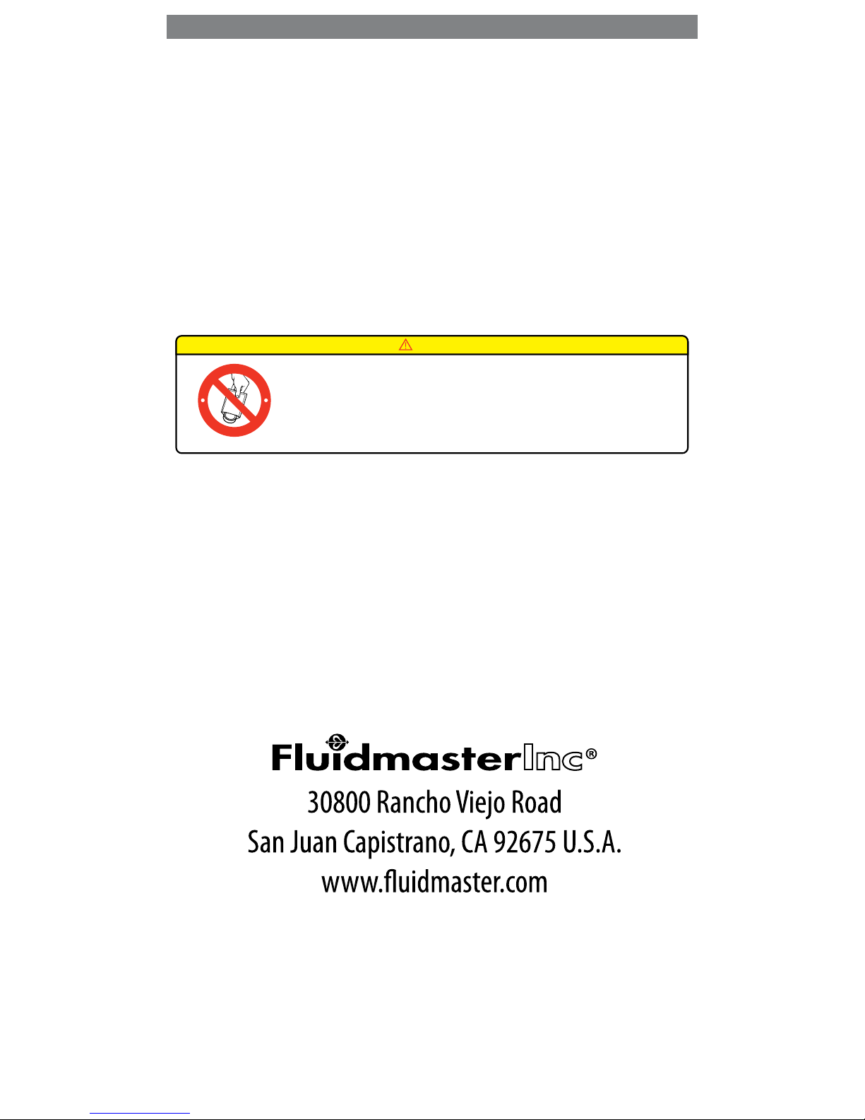
DO NOT USE IN-TANK DROP-IN TOILET BOWL CLEANERS CONTAINING BLEACH OR CHLORINE. Use of such
products will: (1) RESULT IN DAMAGE to tank components and MAY CAUSE FLOODING and PROPERTY
DAMAGE and (2) VOID FLUIDMASTER WARRANTY. DO NOT overtighten nuts or tank/bowl may crack.
N
O
B
L
E
A
C
H
D
R
O
P
-
I
N
S
N
O
B
L
E
A
C
H
D
R
O
P
-
I
N
S
1-800-631-2011
Subject to the “Exclusions” set forth below, Fluidmaster, Inc.® promises to the consumer to repair, or at the option of
Fluidmaster, Inc. to replace any part of this plumbing product which proves to be defective in workmanship or materials
under normal use for 5 years from the date of purchase. All costs of removal, transportation and reinstallation to obtain
warranty service shall be paid by the consumer. During this Limited Express Warranty, Fluidmaster, Inc. will provide
subject to the “Exclusions” section set forth below, all replacement parts free of charge, necessary to correct such defects.
This “Limited Warranty” is null and void if this plumbing product has not been installed and maintained and accordance
with all written instructions accompanying the product or if non-Fluidmaster Inc. component parts are used.
Exclusions: FLUIDMASTER INC. SHALL NOT BE LIABLE FOR INCIDENTAL OR CONSEQUENTIAL DAMAGES, INCLUDING COSTS
OF INSTALLATION, WATER DAMAGE, PERSONAL INJURY OR FOR ANY DAMAGES RESULTING FROM ABUSE OR MISUSE OF THE
PRODUCT, FROM OVERTIGHTENING, FROM USE OF NON-FLUIDMASTER INC. COMPONENT PARTS, OR FROM FAILURE TO
INSTALL OR MAINTAIN THIS PLUMBING PRODUCT IN ACCORDANCE WITH THE WRITTEN INSTRUCTIONS. DO NOT USE IN-TANK
DROP-IN TOILET BOWL CLEANERS CONTAINING BLEACH OR CHLORINE. USE OF SUCH PRODUCTS WILL RESULT IN DAMAGE TO
TANK COMPONENTS AND MAY CAUSE FLOODING AND PROPERTY DAMAGE. USE OF SUCH PRODUCTS WILL VOID THIS
WARRANTY.
WARNING
15
Limited Express Warranty
Page 16
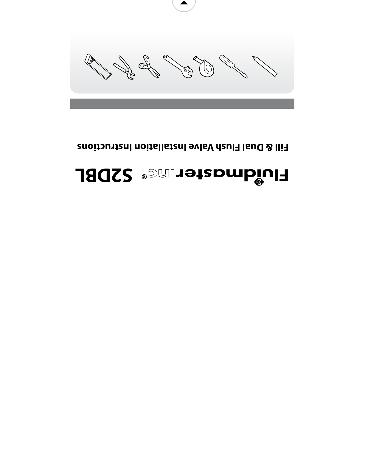
athead
screwdriver
sawscissors channel
locks
tape
measure
crescent
wrench
wax pencil
open
P/N 5-2473 GRev. 4 9/10
www.uidmaster.com
Tools Required
 Loading...