

Page 1
MoviTHERM MIO Series of Intelligent I/O Modules
Intelligent I/O Module for FLIR® FC-Series R Cameras
September 2016
User Manual
Page 2

Revision 1.4
Support
Thank you for selecting MoviTHERM Products.
For product updates and web support, visit:
http://www.movitherm.com
General Disclaimer
MoviTHERM temperature monitoring solutions (hardware and software) are intended for
supplemental thermal monitoring. The device described in this document is only intended to
alert human operators of an emergency situation. The MoviTHERM device is not intended as a
substitute for prudent fire prevention practices and conventional fire prevention equipment,
nor is it a substitute for life and property insurance. The MoviTHERM device must be installed
and serviced by qualified professionals who, along with this documentation package, will
provide information about the capabilities and limitations of the device. While generally very
reliable, the device may not work under all conditions such as (but not limited to) interruptions
to power, component failure, and/or other unanticipated operational conditions that were not
present during installation, testing and validation. When correctly installed and maintained, the
MoviTHERM device explained in this document should reliably provide years of trouble-free
service. All MoviTHERM systems and devices must be used in combination with redundant fire
detection and response systems.
Compliance
The MIO I/O module is CE/FCC compliant. Refer to the MoviTHERM MIO Compliance
documentation supplied with the device.
Trademarks
FLIR, the FLIR logo, and all FLIR product names referenced in this document are trademarks
and/or registered trademarks of FLIR Systems, Inc. and/or its subsidiaries.
Information is subject to change without notice. ©2016 MoviTHERM - All rights reserved.
Page 3

Table of Contents
1 Foreword .............................................................................................................................. 1
2 Device Overview .................................................................................................................. 2
3 Unpacking ............................................................................................................................ 2
4 Connecting the MIO I/O Module ......................................................................................... 3
5 Specifications ....................................................................................................................... 6
6 System Installation and Set-up ............................................................................................ 6
6.1 Configuration Procedure .................................................................................................. 7
6.1.1 IP Configuration ........................................................................................................ 8
6.2 Preparing MIO for Configuration ..................................................................................... 9
6.3 Assigning Actions to Camera Regions: The MIO Controller Utility ................................ 10
6.3.2 The Camera Settings Tab ........................................................................................ 16
6.3.3 The Debug Tab ........................................................................................................ 23
6.4 Recovery Mode .............................................................................................................. 25
6.4.1 Password Reset ....................................................................................................... 26
7 Operations ......................................................................................................................... 27
7.1 I/O Connections .............................................................................................................. 27
7.1.1 Digital Output Pin Definitions ................................................................................. 27
7.1.2 Analog Output Pin Definitions ................................................................................ 28
8 Troubleshooting Common Issues ...................................................................................... 30
9 Appendix A: Default Settings ............................................................................................. 32
10 Appendix B: Technical Specifications ................................................................................. 32
10.1 Absolute Maximum Ratings ........................................................................................... 32
10.2 Operating Specifications ................................................................................................ 32
Page 4

MoviTHERM MIO-FCR-1 Manual
1 Foreword
Congratulations on your purchase of the MoviTHERM MIO Series Intelligent I/O Module. We appreciate
your business and want to make sure that your installation is successful. This manual provides important
information for installation, setup, configuration and care of your new product.
PLEASE MAKE SURE TO READ THE ENTIRE MANUAL CAREFULLY BEFORE OPERATING THIS DEVICE.
Whenever you see the symbol to the left, please pay special attention. This is a warning
symbol. Carefully consider all warnings in this document in order to prevent any mistakes.
The blue light bulb and checkmark symbol indicates a useful tip or information.
We invite any suggestions that you might have for improving our products or this user manual. Please
feel free to contact us at any time with your questions, suggestions or concerns:
MoviTHERM – Advanced Thermography Solutions
15540 Rockfield Blvd., Suite C110
Irvine, CA, USA
Phone: +1 949.699.6600
Fax: +1 949.699.6601
Email: info@movitherm.com
Website: http://www.movitherm.com
Twitter: www.twitter.com/movitherm
MoviTHERM – Advanced Thermography Solutions| 15540 Rockfield Blvd., Suite C110, Irvine, CA, USA| www.movitherm.com
1
Page 5
MoviTHERM MIO-FCR-1 Manual
2 Device Overview
This User’s Guide describes how to install, configure, and use the MoviTHERM MIO Intelligent I/O
device. For detailed device specifications, refer to the specifications section at the end of this document.
The single camera version of the MoviTHERM MIO Intelligent I/O device provides TCP/IP connectivity
for 1 camera over a 100Base-T Ethernet connection. Each unit provides two channels of isolated, looppowered analog (4-20mA) outputs, and two solid state (24VDC) relay outputs.
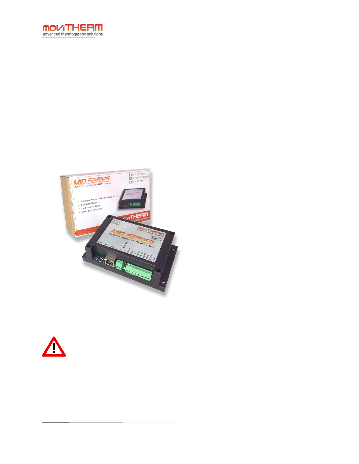
3 Unpacking
The MoviTHERM MIO Intelligent I/O device ships in a custom printed cardboard box, as shown in the
photo below.
After removing the device from the packaging, inspect for damage that may have occurred
during shipping. Damaged devices should not be put into service. Contact your distributor
and/or MoviTHERM immediately if the device appears damaged in any way. If the damages
occurred during shipping, please file a claim with your shipping company.
MoviTHERM – Advanced Thermography Solutions| 15540 Rockfield Blvd., Suite C110, Irvine, CA, USA| www.movitherm.com
2
Page 6

MoviTHERM MIO-FCR-1 Manual
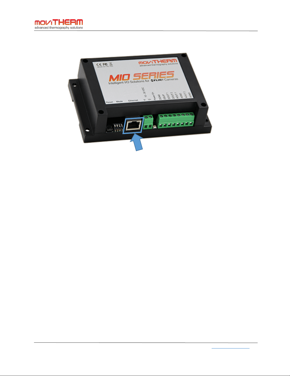
4 Connecting the MIO I/O Module
Inspect the device to locate the various ports and connectors. (See Figure 1.)
Figure 1: MIO Device Connections
The power terminals shown in Figure 1 must be connected to an industrial power supply, or other 1030VDC source. Although the unit is designed to work with a standard 24VDC industrial supply, it will also
work with a 12VDC supply. The input voltage needs to be between 10VDC and 30VDC, so any supply
within this range should be suitable. The selected power source must be regulated and stabilized to
assure reliable performance.
NOTE: No power supply is included with the MIO module. However, power supplies are available, and a
suitable unit can be added as an accessory.
Connect the positive lead of the power supply to the screw terminal marked “V+” and the negative or
ground lead to the terminal marked “V- “. Please make sure not to reverse the polarity. The unit has a
reverse polarity protection built in. However, the unit will not power up if the polarity is reversed.
Under full load conditions, the unit draws about 0.125A (3W). This does not include the current needed
to supply the digital outputs. The digital outputs can source 0.5A each, but will not exceed 1.0A total for
all outputs
MoviTHERM – Advanced Thermography Solutions| 15540 Rockfield Blvd., Suite C110, Irvine, CA, USA| www.movitherm.com
3
Page 7
MoviTHERM MIO-FCR-1 Manual
You can connect the Ethernet RJ-45 port directly to the camera, however it is recommended that you
connect it to a camera network or an Ethernet switch, particularly if you have multiple MIO units and
multiple cameras. You will also need to connect the MIO unit to a PC or laptop for configuring the unit.
Connecting the MIO, the camera, and the PC to an Ethernet switch permits you to configure both the
camera and the MIO module at the same time.
Connect the 4-20mA analog outputs to any device with 4-20mA signal inputs, such as industrial PLCs, 420mA data loggers, 4-20mA signal monitoring/alarm devices, etc. Keep in mind that from the
perspective of the MoviTHERM MIO I/O module, these are outputs. The 4 to 20mA outputs are active, or
loop powered. This indicates that they will provide a loop voltage to the connected device. No additional
power source is necessary or should be added. Make sure to observe the connection polarity of the 4 to
20mA device.
Connect the digital outputs to discrete signal inputs on alarms, warning lamps, auto-dialers, PLCs, etc.
For more details on how to connect devices, please go to Section 7.1 – I/O Connections.
Any number of connection scenarios are possible using the MIO signal outputs. Figure 2 illustrates a
typical installation scenario, and offers some examples of the types of industrial devices that can be
connected to the MIO.
MoviTHERM – Advanced Thermography Solutions| 15540 Rockfield Blvd., Suite C110, Irvine, CA, USA| www.movitherm.com
4
Page 8
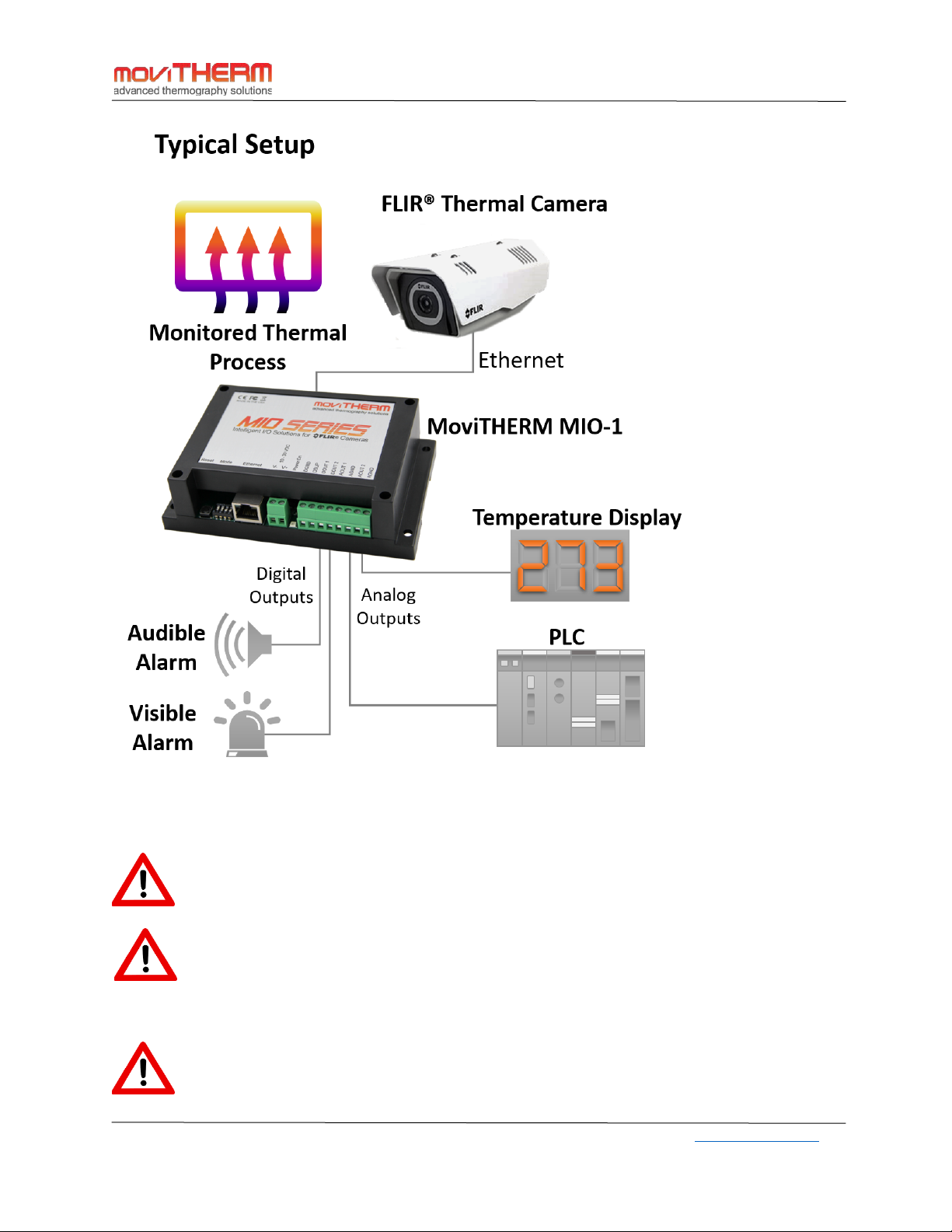
MoviTHERM MIO-FCR-1 Manual
Figure 2: A typical MoviTHERM MIO Monitoring Installation
Do not operate the device in a manner that is not specified in this document. Misuse of the
device may result in a malfunction or safety hazard. It will also void the warranty.
Never operate this device in an explosive environment where flammable gases, dust, fumes
or other volatile materials may be present. If you must operate this device in a hazardous or
explosive environment, it must be installed in a suitably rated enclosure with the necessary
provisions.
To ensure proper performance consistent with the specifications of this device, please
carefully read this user manual and observe all cautions, operating conditions and limits.
MoviTHERM – Advanced Thermography Solutions| 15540 Rockfield Blvd., Suite C110, Irvine, CA, USA| www.movitherm.com
5
Page 9
Model
MIO-FCR-1
Compatible Cameras
FLIR® FC-Series R
Maximum Cameras Supported
1
Ethernet Connection
100Base-T
Communication Protocol
Modbus TCP/IP
4-20mA Transmitter Channels
2 CH, Group Isolated, Self-Powered
Digital Output Channels
2
Digital Output Current
0.5A per Channel, 1.0A all Channels
Digital Output Voltage
10-30VDC
Power Supply Voltage
24 VDC
Maximum Power Consumption
3W
Dimensions
5.7 x 3.6 x 1.6 in (145 x 90 x 40 mm)
Weight
0.5 lbs. (0.23 kg)
Enclosure Material
ABS Plastic
Operating Temperature
0°C to 50°C (32°F to 122°F)
Relative Humidity
0% to 95% RH, non-condensing
5 Specifications
MoviTHERM MIO-FCR-1 Manual
6 System Installation and Set-up
The MoviTHERM MIO Series of Intelligent I/O modules are built into rugged ABS plastic enclosures. The
ABS enclosures are intended to protect the internal electronics for general handling and from minor
impact, but are not designed to protect the device from harsh industrial environments, or exposure in
outdoor installations. Like most industrial devices of this nature, the MIO I/O module is intended to be
mounted inside an existing electrical cabinet or other protective enclosure.
The MIO I/O Module is rated NEMA1 / IP20
Enclosures are constructed for indoor use. They provide a degree of protection to personnel against
incidental contact with the enclosed equipment and to provide a degree of protection against falling
dirt. Internal electronics are protected against solid foreign objects of 12mm in diameter and greater.
The device is NOT protected against water.
The MIO I/O module is not protected against ingress of dust, conductive particles, moisture
or liquid splashing.
For installations in dirty, dusty, hot, wet, freezing or otherwise harsh or hazardous areas,
provisions must be made to adequately protect the MIO I/O module.
MoviTHERM – Advanced Thermography Solutions| 15540 Rockfield Blvd., Suite C110, Irvine, CA, USA| www.movitherm.com
6
Page 10

MoviTHERM MIO-FCR-1 Manual
Please do not stick any tools or metal objects inside the MIO module. This may create an
electrical shortcut and permanently damage the unit. This will also void the warranty.
For indoor industrial or outdoor environments, we recommend placing the MIO I/O module inside an
electrical enclosure rated at least NEMA4 or NEMA4x. No cooling is required, provided the inside
temperature of the protective enclosure does not exceed the max allowable operating temperature of
the MIO module. If the expected internal enclosure temperature may exceed the max operating
temperature, active cooling is recommended to ensure trouble-free operations.
To ensure proper operation and continuing reliability, all set-up and configuration tasks should be
completed by qualified engineers or service technicians. The information in this manual provides some
direction, but should not be considered a substitute for extensive experience.
If you are unsure how to proceed, contact your distributor or MoviTHERM technical
support (support@movitherm.com
) for further direction. Please include the serial number
of your MoviTHERM MIO unit. Alternatively, visit the MoviTHERM Website
www.movitherm.com and use the contact methods provided on the contact page.
6.1 Configuration Procedure
After the electrical connections have been made and verified, it is time to configure the camera and the
MoviTHERM MIO device. FLIR FC-R Series cameras are configured using the camera’s built in web server.
(Additional information about configuring the FLIR camera can be found in the camera documentation.)
The MIO device is configured using the browser-based MoviTHERM MIO Configuration Utility, as
discussed later in the manual.
System Configuration is a four step process:
1) Set the camera to a fixed IP addresses using the camera’s built-in web browser interface.
2) Set up the inspection regions (Regions of Interest or “ROIs”) using the camera’s built it web
browser interface.
3) Define the thresholds and action criteria for each ROI using the browser-based MoviTHERM
MIO Configuration Utility.
4) Configure the MIO board response using the MoviTHERM MIO Configuration Utility.
MoviTHERM – Advanced Thermography Solutions| 15540 Rockfield Blvd., Suite C110, Irvine, CA, USA| www.movitherm.com
7
Page 11
MoviTHERM MIO-FCR-1 Manual
Steps 3 & 4 cannot be completed until Steps 1 and 2 are complete. Step 1 requires the
FLIR® FC-Series R camera’s built-in web browser interface. Step 2 is also completed using
the built-in web interface. This application is deployed using any standards-compliant
Internet web browser (Microsoft Edge, IE, Google Chrome, Firefox). Steps 3 & 4 also use
the web browser interface to access the MoviTHERM MIO Configuration Utility.
Configuring the FC-Series R camera’s “ROIs” (Regions of Interest) also requires the
camera’s built in web browser. Consult the appropriate FLIR camera user manual for more
details on how to setup the camera.
6.1.1 IP Configuration
It is important to understand that although the MIO device and the cameras share a single Ethernet
connection, the camera, the MIO device, and the computer (PC) used to configure the system must have
separate and unique TCP/IP addresses. The camera, MIO, and PC must also be configured to use a static
IP addresses. Use the FC-Series R camera’s built-in web browser interface to set the IP address.
The MoviTHERM MIO Configuration Utility will be used to set up the IP address on the MIO device (as
discussed in the next chapter).
IP SUBNET CONFIGURATION - IMPORTANT NOTE:
The camera, the MIO device, and the PC must each be assigned a unique IP address. However,
in order to share the same Ethernet cable connection, all of the IP addresses must reside within
the same subnet. This is most easily accomplished by ensuring that the 1
address fields are common for all devices, while the 4
th
field is unique for each device.
st
, 2nd, and 3rd IP
For example, the default IP address for the MIO device is defined as follows:
MIO IP address: 192.168.1.2
Subnet mask: 255.255.255.0
If this default is left unchanged, suitable camera IP addresses might be:
Camera IP address 1: 192.168.1.3
Camera IP address 2: 192.168.1.4
Camera IP address 3: 192.168.1.89 (etc.)
If the MIO device IP is modified (as outlined later in this document), the camera and PC IP
addresses may need to be updated accordingly.
MoviTHERM – Advanced Thermography Solutions| 15540 Rockfield Blvd., Suite C110, Irvine, CA, USA| www.movitherm.com
8
Page 12

MoviTHERM MIO-FCR-1 Manual
After the camera and MIO IP addresses have been assigned, you will be ready to define the Regions of
Interest that will be used by the MIO device.
When working with the MIO module, you need to set up the regions using the Radiometery
tab, as shown here. NOTE: The Alarm must be enabled for the region (as shown here) if you
want the MIO to detect it. Refer to the FC-Series R User Manual for detailed information
about defining the regions of interest for the FC-Series R camera.
You must complete the Region of Interest configuration in the camera before moving on to configure
the MoviTHERM MIO device.
6.2 Preparing MIO for Configuration
You will need to have the camera’s regions of interest defined before you can configure the MIO. The
MIO needs to find the configured regions of interest in the camera in order to perform the selected
actions. You can configure one or many ROIs. You are limited only by the number of regions available in
the camera, and the available outputs on the MIO I/O. If more outputs are needed, or you need to
monitor more than one camera in your application, simply add additional single-channel or a multichannel MIO I/O modules to your network.
MoviTHERM – Advanced Thermography Solutions| 15540 Rockfield Blvd., Suite C110, Irvine, CA, USA| www.movitherm.com
9
Page 13

MoviTHERM MIO-FCR-1 Manual
Supported Web Browsers - The following web browsers are supported by the MIO. If you
are using an older version than the supported version and are experiencing issues, update
to the latest version or use another supported browser.
Microsoft Edge – 38.0
Google Chrome – 53.0
Firefox – 48.0
6.3 Assigning Actions to Camera Regions: The MIO Controller Utility
Once Regions have been defined in the camera, you are ready to assign actions based on temperatures
detected. Start by launching a web browser (Google Chrome, Microsoft Edge, Firefox) from your
Windows Desktop or Start Menu. When the browser window opens, type the MIO Controller Board IP
address into the Address (URL) field at the top of the browser window, as shown in Figure 4.
The MIO’s default IP address is: 192.168.1.2
The MIO’s IP address is user-configurable. If you are uncertain about the MIO’s IP address setting, start
with the default. If this doesn’t provide access, refer to the notes on the next page.
Figure 4: MIO Access Log-in Dialog
MoviTHERM – Advanced Thermography Solutions| 15540 Rockfield Blvd., Suite C110, Irvine, CA, USA| www.movitherm.com
10
Page 14

MoviTHERM MIO-FCR-1 Manual
If the correct IP address is entered, the Password Login dialog will appear in the browser window as
shown here.
Enter the Administrator log-in password in the field provided, and click the Log In button to continue.
When the correct password has been entered, the Device Settings Tab will open in the browser window,
as shown in Figure 5.
For simplicity, the default log-in password is set to “password”. After system installation,
you may want to change the password to reduce the potential for unauthorized system
access. (Additional information about changing the password can be found in the section
that discusses Recovery Mode.)
The MoviTHERM MIO Device IP Address is pre-configured to 192.168.1.2. This is the factory
default IP setting, but this address is configurable. If the IP address has been changed, you will
need to provide a different address. If you know the correct address, enter it into the Address
(URL) field. If you are uncertain, try the default IP (192.168.1.2) first. If you are unable to
connect, you may need to perform a Network Reset. (Refer to the IP Address Reset section
later in this chapter.)
MoviTHERM – Advanced Thermography Solutions| 15540 Rockfield Blvd., Suite C110, Irvine, CA, USA| www.movitherm.com
11
Page 15

MoviTHERM MIO-FCR-1 Manual
Figure 5: The MIO Controller Utility opens to the Device Settings tab after the correct password has been entered.
The contents of the Device Information fields will depend on the MIO device and camera.
6.3.1.1 The Device Settings Tab
The Device Settings tab (shown in Figure 5) is the default start-up page. When you access the MIO Board
Configuration from your browser, this is the tab that will appear after entering the correct log-in
password. The text fields with a white background are editable fields. The text fields with a grey
background display current system parameters, but are not user-editable.
The Device Settings tab is used to:
1) set the Network Configuration (IP Address and Subnet),
2) enter an optional user-defined Device Name
3) execute a firmware update
6.3.1.2 Network Configuration
To change the Network Configuration, simply type the new Device IP address and Subnet mask in the
fields provided. Similarly, to change the Device name, simply type a user-specified name into the Device
name field provided. Click “Save Settings and Reboot” to save the changes.
MoviTHERM – Advanced Thermography Solutions| 15540 Rockfield Blvd., Suite C110, Irvine, CA, USA| www.movitherm.com
12
Page 16

MoviTHERM MIO-FCR-1 Manual
Note: If you change the IP address and then click “Save Settings and Reboot”, the board will run through
a short reset cycle before opening a link to the new IP address. When the browser page updates, the
Device IP address and Subnet mask fields will reflect the changes. (See Figure 6.)
Figure 6: IP Address changed - view after Save and Reboot
6.3.1.3 IP Address Reset
If you changed the IP Address, but have forgotten the new setting, an IP Address Reset operation will
temporarily reset the IP address to the factory default. To reset the IP address, you will need to access
the DIP switches on the MIO device. (The DIP switches can be accessed through the cut-out port located
to the left of the MIO Ethernet port.)
DIP Switches and Reset Button
locations
When you have located the DIP switches, follow these steps to reset the IP address to the factory
default setting: 192.168.1.2 (Subnet Mask:
255.255.255.0)
While the unit is powered on:
Step 1: Turn on the IP Reset DIP switch
(see Figure 7)
MoviTHERM – Advanced Thermography Solutions| 15540 Rockfield Blvd., Suite C110, Irvine, CA, USA| www.movitherm.com
13
Page 17

MoviTHERM MIO-FCR-1 Manual
Figure 7: Set the IP reset DIP Switch to ON
Figure 8: Clear the IP reset DIP Switch (OFF)
Step 2: Reset the device by either:
a) Powering module off, waiting 10 seconds,
then powering back on
Or
b) Pressing the reset button. The reset button is located to the immediate left of the DIP Switches.
(See blue highlighted area and arrow in the image above.)
Step 3: After the device reboots, log in to the device using the default IP address: 192.168.1.2
Step 4: Turn off the IP Reset DIP switch
(see Figure 8)
For setting the IP Address back to a user-defined value, return to the previous Network
Configuration section of this document. Keep in mind that every time you are changing
the IP address of the device, the connection in your browser (and all other connected
devices) may be lost. Make sure to change the IP address in the browser to the newly
configured IP address to re-establish the connection.
6.3.1.4 Firmware Update
The Firmware Update option at the top of the Device Settings tab is an advanced feature that allows you
to quickly and easily upgrade the Firmware (embedded software) running on the board. Under normal
conditions, you will rarely need to update the Firmware. (MoviTHERM may release firmware updates
from time to time to add new functionality to the MIO, or to address firmware changes in the FLIR
camera.) You will not be required to perform this operation under normal, everyday operating
conditions, but if an update is required, the Firmware Update process involves the following steps:
MoviTHERM – Advanced Thermography Solutions| 15540 Rockfield Blvd., Suite C110, Irvine, CA, USA| www.movitherm.com
14
Page 18

1) Download the Firmware file to
Figure 9: Buttons for initiating the Firmware Update
your PC
2) Click the “Choose File” button
under “Firmware Update” on the
“Device Settings” tab (Fig. 9)
3) Navigate to the Firmware file
(from Step 1) using the file
browser, and select it. The
filename will appear next to the
“Choose File” button.
4) Click the “Update” button under
“Firmware Update” on the
“Device Settings” tab (Fig. 9)
5) The firmware update will be
loaded into the MIO Device. The
device will reboot and
reconnect.
MoviTHERM MIO-FCR-1 Manual
When the Firmware update cycle is complete, you will be returned the Device Settings Tab.
MoviTHERM – Advanced Thermography Solutions| 15540 Rockfield Blvd., Suite C110, Irvine, CA, USA| www.movitherm.com
15
Page 19

MoviTHERM MIO-FCR-1 Manual
6.3.2 The Camera Settings Tab
The Camera Settings Tab is used to link the camera IP addresses to the MIO Controller board. This step
permits the cameras to communicate with the board, enabling its functionality. When you click on the
Camera Settings tab, the tab depicted in Figure 10 loads into the browser window.
Figure 10: The Camera Settings Tab - awaiting configuration
Enter a name or alias for the camera in the field provided, along with the corresponding
IP address for the camera, as illustrated in Figure 11, and press the “Save Configuration”
button. As the MIO Board connects to the cameras, the green “Connected” text will
replace the red “Not Connected” text to the right of the camera specification, as shown
in Figure 11.
The “Alias” allows the user to provide a more meaningful name or reference to the camera, rather than
having to memorize a cryptic IP address number. The alias name has no other use than that and will not
affect any functionality.
MoviTHERM – Advanced Thermography Solutions| 15540 Rockfield Blvd., Suite C110, Irvine, CA, USA| www.movitherm.com
16
Page 20

MoviTHERM MIO-FCR-1 Manual
Figure 11: Sample Camera Configuration
6.3.2.1 Saving and Loading Configurations
The MIO device maintains one complete configuration in non-volatile memory. You can use the “Save
Configuration” button to store the current configuration as displayed on the Camera Settings tab into
the device memory. On power reset, the most recently saved configuration is used by the device. You
can also use the “Get Current Settings” button to load the most recently saved configuration from the
device memory into the Camera Settings tab for inspection or further editing.
6.3.2.2 The Script Commands Tab
After the camera settings have been set up, the next task is to set up the script commands that create
the intended system responses. The Script Commands tab is used to configure the commands
configuration. (See Figure 12.)
MoviTHERM – Advanced Thermography Solutions| 15540 Rockfield Blvd., Suite C110, Irvine, CA, USA| www.movitherm.com
17
Page 21

MoviTHERM MIO-FCR-1 Manual
Figure 12: The Script Commands tab - prior to configuration.
The configuration procedure is straight-forward:
1) Select a Command from the left-most pull-down menu (as shown in Figure 13)
2) Assign the selected Command to a Region of Interest/Alarm ID by selecting it using the pull-
down menu. (The Regions of Interest correspond to the Alarm IDs and must be predefined in the
camera using FC-Series R web browser interface as discussed previously.)
3) In the case of an Analog Output command, assign the Analog Output Mode, “Linear” or
“Threshold” (information about these modes is provided below).
4) If “Threshold” mode is used, set the Temperature Threshold(s) needed to initiate the specified
action in the Low Temperature box. If “Linear” mode is used, enter the value which should
correspond to 4 mA in the Low Temperature box and the value which should correspond to 20
mA in the High Temperature box.
Repeat these steps for the Analog and/or Digital channels as needed, then save the configuration by
clicking the “Save Configuration” button.
MoviTHERM – Advanced Thermography Solutions| 15540 Rockfield Blvd., Suite C110, Irvine, CA, USA| www.movitherm.com
18
Page 22

MoviTHERM MIO-FCR-1 Manual
Figure 13: Command pull-down menu options
You can assign multiple outputs (digital and analog) to the same camera, if needed. For
example, if you have four regions of interest configured within one and the same
camera, you can also assign two separate analog outputs and two separate digital
outputs to each of these four regions, each with their own alarm threshold. Or
alternatively, you could assign the analog 4 to 20mA outputs to the same regions as the
digital outputs for external monitoring or control. It is entirely up to you, how you utilize
the resources in the MIO I/O module. If you run out of outputs, you can add another
MIO I/O module to the network and expand your system that way.
6.3.2.3 Command Options
The Command Options can be summarized in the following categories:
1) System Status
2) Delta Temperature
3) Internal Camera Temperature
4) Spot Temperature
5) Box Temperature (Max, Min, or Average)
6) Alarm trigger
MoviTHERM – Advanced Thermography Solutions| 15540 Rockfield Blvd., Suite C110, Irvine, CA, USA| www.movitherm.com
19
Page 23

MoviTHERM MIO-FCR-1 Manual
System Status
System Status is a special configuration option that can be used to monitor camera connectivity. When
the System Status Command is assigned to an output channel, the selected channel can be used to
monitor Ethernet connectivity. If all the cameras entered in the “Camera Settings” tab have active
Ethernet connections to the MIO (0.0.0.0 IP address are not considered), the output will be logical
"HIGH" (20mA output). If one or more camera connectivity issues are detected, the selected output
channel will reflect a logical "LOW" (4.0 mA) state.
Delta Temperature
The Delta Temperature command enables you to initiate an action based on the difference between two
parameters. For example, an action could be based on the difference between the minimum and
maximum temperature readings within a single region. Alternatively, two regions could be compared, or
the camera’s internal temperature register could even be compared with a region in the image. The
difference between any two eligible camera parameters can be used as the basis for the delta
comparison. (Refer to the FLIR Camera user manual for how to setup delta temperature functions in the
camera)
Internal Camera Temperature
The Internal Camera Temperature option selects the camera’s internal temperature as the data source.
This option can be used to monitor the temperature environment of the camera, and alert the user to
unusual operating conditions.
Spot Temperature
Select the Spot Temperature option to use a predefined spot temperature as the data source. (Refer to
the FLIR Camera manual for more details about configuring a Spot Temperature measurement.)
Box Temperature (Max, Min, or Average)
Select the Box Temperature option to use a predefined Box temperature (max, min or average) as the
data source. . (Refer to the FLIR Camera manual for more details about configuring a Box Temperature
measurement.)
Alarm Trigger
Each camera can be configured to generate Alarm Trigger events in response to a variety of inputs.
Measurement results from within the image, the instantaneous state of a digital input, or even a
camera’s internal temperature could potentially be configured to generate an alarm. Selecting the Alarm
Trigger option assigns the state of the alarm flag as the data source for MIO device operations. (Refer to
the FLIR Camera manual for more details about configuring alarms in the camera.)
MoviTHERM – Advanced Thermography Solutions| 15540 Rockfield Blvd., Suite C110, Irvine, CA, USA| www.movitherm.com
20
Page 24

MoviTHERM MIO-FCR-1 Manual
Alarm ID Selection menu
6.3.2.4 Alarm ID Selection
The Alarm Id field is located to the right of the Command field. The available Alarm Id options will
depend on the Command option selected. For example, if you select the System Status, Internal Camera
Temperature, or Alarm 0-3 option in the Command pull-down, the Region of Interest specification is not
relevant. The Region of Interest field will be disabled and unavailable for editing. However, if you select
a Spot or Box source in the Command field, it becomes necessary to specify which of the pre-defined
Spots or Boxes applies. In this case, the Alarm Id field will be enabled and populated with all the
available regions (Spots and Boxes). After specifying the appropriate region, you can move on to specify
the Output Mode (in the case of Analog Output channels), and the temperature threshold(s).
6.3.2.5 Analog Output Mode
The Analog Output Mode selection determines the behavior of the specific analog output channel. Two
options are available: Linear Output or Threshold Output. When Linear Output is selected, the specified
output channel will produce a scaled 4-20mA signal based on the selected Command and Region of
Interest. The scaling is based on the values entered in the Low and High Temperature fields (4mA for
values ≤ Low Temperature, 20mA for values ≥ High Temperature). When Threshold Output is selected,
the output channel will produce a discrete low (4mA) or high (20mA) signal, based on the temperature
threshold value(s) set in the Low Temperature field.
You can scale the 4 to 20mA output to either the selected temperature range of the
camera, or a custom scale. For example, if the selected temperature range of the
camera is 0°C to 350°C, then enter ‘0’ in the field “Low Temperature” and ‘350’ in the
field named “High Temperature. In this example, a 4mA output signal equals to 0°C and
20mA equals to 350°C. Setting the low temperature or high temperature outside the
selected camera temperature range is not recommended. However, you may select a
different range within the calibrated temperature range of the camera. This is useful, if
you know that your process temperature may never go below or above a certain value.
For example, your process temperature may be between 70°C and 150°C, while the
temperature range of the camera is 0°C to 350°C. Setting the scaling of the 4 to 20mA
output of the MIO module to your min. and max. range of your expected process
temperature allows you to stretch the range across the entire 4 to 20mA range.
However, this will not increase the accuracy of your system.
MoviTHERM – Advanced Thermography Solutions| 15540 Rockfield Blvd., Suite C110, Irvine, CA, USA| www.movitherm.com
21
Page 25

It is also possible to use the analog 4 to 20mA outputs as threshold or alarm outputs. In
other words, if you select the “Threshold” option, rather than the “Linear Output”
option. This function allows any analog output to behave like a digital output in a sense.
In this case a 4mA current indicates a logic low signal and a 20mA current signals a logic
high or alarm. This is useful, if you run out of digital outputs and want to extend the I/O
of the module. Some 4 to 20mA controllers also “understand” this sort of signaling as
alarm condition.
An example of a completed configuration is shown in Figure 14.
MoviTHERM MIO-FCR-1 Manual
Figure 14: Sample Configuration
To summarize, each output channel is configured via the Script Commands tab (as shown in Figure 14).
The usual procedure is to start by selecting a camera using the pull-down camera selector menu. After
selecting a camera, a Command should be specified. If the selected Command specifies a Spot or Box
temperature, you will also need to select an Alarm Id/Region of Interest. For Analog Outputs, an Analog
Output Mode must be selected – either a Linear 4-20 mA analog signal that changes proportionally
based on the selected Region of Interest, or a discrete 4 or 20mA Threshold Output, based on a
comparison of the Region of Interest with the temperature threshold settings. (Note that the Digital
Channels behave similarly to the Analog Threshold Output mode.)
MoviTHERM – Advanced Thermography Solutions| 15540 Rockfield Blvd., Suite C110, Irvine, CA, USA| www.movitherm.com
22
Page 26

MoviTHERM MIO-FCR-1 Manual
6.3.2.6 Saving and Loading Configurations
Just like the Camera Configuration (discussed previously), the MIO device maintains one complete set of
Script Commands in non-volatile memory. You can use the “Save Configuration” button to store the
current configuration as displayed on the Script Commands tab into the device memory. On power
reset, the most recently saved configuration is used by the device. You can also use the “Get Current
Settings” button to load the most recently saved configuration from the device memory into the Script
Commands tab for inspection or further editing.
6.3.3 The Debug Tab
After the configuration has been defined, the Debug Tab (in Figure 15) provides a convenient,
interactive window into the real-time operation of the MIO Board. Using the Debug tab, you can observe
the current status of all output channels and DIP switches at a glance. You can use this tab to validate
output channel operations.
Figure 15: The Debug Tab shows the current output state of each MIO Board output channels and the DIP switch states
MoviTHERM – Advanced Thermography Solutions| 15540 Rockfield Blvd., Suite C110, Irvine, CA, USA| www.movitherm.com
23
Page 27

MoviTHERM MIO-FCR-1 Manual
6.3.3.1 MIO Board DIP Switches
The DIP Switches control advanced board functions. The position of each switch is shown below in
Figure 16.
Figure 16: MIO Board DIP Switches
6.3.3.2 DIP Switch Functions
Switch 1 – Filter: Enabling the Filter switch activates a running average filter (10 samples) on the
temperature INPUTS. This function may provide better performance for monitoring applications
involving a constantly variable temperature source such as a flickering flame. The filter is globally
applied to all seven cameras and all configured regions of interest.
Switch 2 – IP Reset: The IP Reset switch is used to reset the IP address to the factory default setting. (For
more information, refer to IP Address Reset under the Device Settings Tab discussions earlier in this
document.)
Switch 3 – 4mA Test: When enabled, all analog channels will output a “logical low” 4mA signal.
Switch 4 – 20mA Test: When enabled, all analog channels will output a “logical high” 20mA signal.
NOTE: When both Switch 3 (4mA Test) and Switch 4 (20mA Test) are enabled, a 12mA half-scale signal
will be output on all analog channels
Switches 5-8: [Reserved for Future Expansion]
All MIO Series I/O modules have a built-in loop calibrator and simulator. The 4 to
20mA signal has 16-bit resolution and is very accurate. By using dip switch 3,4 and 3&4
together you can simulate 4mA, 12mA or 20mA in your setup. The current that the
board outputs is being indicated on the debug page. Therefore, you do not need a
separate instrument such as a loop calibrator or multi-meter to verify your system. This
feature lets you troubleshoot issue and quickly very how your scaling is setup on the
MIO I/O module as well as on the receiving device.
MoviTHERM – Advanced Thermography Solutions| 15540 Rockfield Blvd., Suite C110, Irvine, CA, USA| www.movitherm.com
24
Page 28

MoviTHERM MIO-FCR-1 Manual
6.4 Recovery Mode
The Recovery Mode (depicted in Figure 17) is an advanced mode that can be used to reset the MIO
device to its original factory settings. Similar in appearance to the Device Settings Tab discussed
previously, the Recovery page includes two key differences:
1) a button to clear camera and script settings
2) a field to enter a new system password.
To enter into Recovery Mode, you must first set all the DIP switches to the ON position and reset the
board. The reset function is activated by pressing the Reset button (located to the left of the DIP
switches), or by power-cycling the unit.
Only use the Recovery Mode as a last resort. This function clears all system settings. The
recovery mode is typically only necessary if a firmware update has failed or when you are
unable to access the unit via the web-browser.
Before attempting a system recovery, please make sure to try an IP Address reset first to see
if you can access the MIO I/O module. Sometimes Windows Firewall settings, Virus
Scanners, web browser privacy or Windows security settings may be the issue preventing
you from accessing the unit. Check these first.
MoviTHERM – Advanced Thermography Solutions| 15540 Rockfield Blvd., Suite C110, Irvine, CA, USA| www.movitherm.com
25
Page 29

MoviTHERM MIO-FCR-1 Manual
Figure 17: Set all DIP switches ON and power-cycle to open the Recovery panel
6.4.1 Password Reset
To reset the access password, make sure the unit is already in “Recovery Bootloader Mode”
1. Type a new password into the current password field
2. Switch all DIP switches to the OFF position
3. Click the “Save Settings and Reboot” button
4. When the system restarts, use the new password to log into the Device Settings tab
5. Switch the DIP switches switched to OFF under 2.) back to the desired position
MoviTHERM – Advanced Thermography Solutions| 15540 Rockfield Blvd., Suite C110, Irvine, CA, USA| www.movitherm.com
26
Page 30

MoviTHERM MIO-FCR-1 Manual
7 Operations
The MIO-FCR-1 provides two (2) 4 to 20mA analog outputs and two (2) digital outputs. In order to
benefit from this connectivity, the MIO signals must be connected to other devices such as PLCs, dataloggers, warning lamps, alarm equipment, etc. This chapter is devoted to connecting the MIO unit to
external devices.
7.1 I/O Connections
All I/O connections are made via the screw terminal I/O Connectors as denoted in Figure 18.
Figure 18: I/O Mapping and Connectivity
The I/O ports are organized into two groups: Digital Outputs and Analog Outputs. When looking at the
side of the MIO enclosure with the I/O port cutouts, the Digital Outputs appear to the left of the Analog
outputs.
7.1.1 Digital Output Pin Definitions
From left to right, the DOUT pins are defined as:
Pin 1: DGND (DOUT Ground)
Pin 2: DSUP (DOUT Supply)
Pin 3: DOUT 1
Pin 4: DOUT 2
MoviTHERM – Advanced Thermography Solutions| 15540 Rockfield Blvd., Suite C110, Irvine, CA, USA| www.movitherm.com
27
Page 31

Refer to Figure 19 for DOUT channel circuit and connection diagram.
7.1.2 Analog Output Pin Definitions
From left to right, the AOUT pins are defined as:
Pin 5: AOUT 1
Pin 6: AGND
Pin 7: AOUT 2
Pin 8: AGND
Refer to Figure 19 for AOUT channel circuit and connection diagram.
MoviTHERM MIO-FCR-1 Manual
Figure 19: DOUT and AOUT Channel Circuit Diagrams
MoviTHERM – Advanced Thermography Solutions| 15540 Rockfield Blvd., Suite C110, Irvine, CA, USA| www.movitherm.com
28
Page 32

MoviTHERM MIO-FCR-1 Manual
NOTE: If using the digital output to signal a digital input device, a pull-down resistor must be used. A
The DOUT signals (DOUT 1 and DOUT 2) when active (turned on) will source the voltage connected to
the DSUP terminal with reference to DGND. Therefore, an external power supply needs to be connected
to the terminal DSUP (‘+’) and DGND (‘-‘). The supplied voltage can be between 9 and 34VDC. Most
common voltages used are either +12VDC or +24VDC.
Each output can source up to 0.5A individually. However, the total sum of all current sourced
through any of the digital outputs cannot and shall not exceed 1.0A. If higher currents are
required, please add a relay or other suitable power switch to protect the output.
If all outputs are turned on, then the following needs to be observed:
1.0A/2 = 0.5A max. per digital output. In other words, if you would like to connect a
relay to each output, please make sure that each relay coil draws <= 0.5A.
Example: You are using a 12VDC/1A external power supply for the digital outputs. The
power supply is connected to DSUP (‘+’) and DGND (‘-‘). You have two electromechanical relays with 12VDC coils. The coil resistance is 120Ω.
To calculate the required current per each relay, we can use the Ohm’s Law.
Coil Current = Coil Voltage/Coil Resistance
= 12V/120Ω
= 0.1A or 100mA
The above relay would be suitable, since it only draws 0.1A.
0.1A x 2 Channels = 0.2A total.
The digital outputs are protected against thermal overload, over current and transients from inductive
loads. It is good engineering practice to select relays with a coil current less than 0.15A or 150mA.
The positive (+) terminal of the external (load) device is connected to the DOUT channel on the MIO
device, as illustrated in Figure 18. The load’s negative (-) terminal must be connected to the Digital
Ground (Pin 1), which will share a connection to the negative (-) terminal of the 9-34VDC digital power
supply.
common value is 10K. This may also be the case for driving SSR (Solid State Relays).
The AOUT signal pairs are “self-powered” 4-20mA output signals. Loop power is provided by an onboard isolated 24VDC power supply. The recommended wiring configuration is depicted in Figures 18
and 19. The positive (+) terminal of the power source should be connected to the lower-numbered pin
of the pair (i.e. Pin 5 for AOUT 1 or Pin 7 for AOUT 2). The negative (-) load terminal should be connected
to the AGRND, which is connected to the negative (-) terminal of the power source.
MoviTHERM – Advanced Thermography Solutions| 15540 Rockfield Blvd., Suite C110, Irvine, CA, USA| www.movitherm.com
29
Page 33

MoviTHERM MIO-FCR-1 Manual
Camera Image Issue
Possible Causes
Recommended Action
Unable to connect to
1) No Camera Power
1) Check Power Supply and Cables
Camera connection lost
1) Camera Power cable broken
(overheating)
1) Check Power Supply and Cables
A) Camera connection
1) Camera Start-up underway
running.
1) Wait until start-up complete
Camera images appear
1) Camera Region or MIO
1) Verify Output Channel parameters
meter or 4-20mA loop tested
Analog output current is
1) Analog channel is reading from
1) Verify proper camera and ROI
MIO device to the OFF position
AOUT(n) channels are group isolated outputs, which is to say that they are isolated from the main 24V
power and all other digital output signals, but not from each other. All AGNDs are connected to each
other internally.
8 Troubleshooting Common Issues
the Thermal Camera
over Ethernet
during normal operation
after working
previously.
appears to be OK, but
no image appears.
B) Camera image is
blank and/or the
camera temperature
range is much higher
than expected.
as expected, but no
output signal is
generated.
2) No Ethernet Connection
3) Incorrect IP Settings
4) Camera Hardware Failure
2) Ethernet cable broken
3) Ethernet Bandwidth Limitation
4) Camera Software Fault
5) Camera Hardware Failure
6) Camera thermal issue
2) Camera temperature range is
not properly set*.
3) Camera Software Fault
4) Camera Hardware Failure
*NOTE: This may happen if the
camera Ethernet connection is
unplugged while the camera is
Configuration Error
2) Output line connection fault
3) I/O Module Error or hardware
failure
2) Check Ethernet cables, switches, etc.
3) Set IP address with FLIR IP Config
4) Check Camera operations
2) Check Ethernet Cable
3) Check Router/Switch throughput
4) Power-cycle the Camera
5) Check Camera operations
6) Power down and allow to cool.
2) Set correct Camera Configuration in
web browser
3) Power-cycle the Camera
4) Check Camera operations
are set correctly on the MIO Utility’s
Script Commands tab
2) Check Output signal wiring
3) Verify Output signal using a volt
unaffected by camera
input.
MoviTHERM – Advanced Thermography Solutions| 15540 Rockfield Blvd., Suite C110, Irvine, CA, USA| www.movitherm.com
30
incorrect Region of Interest
2) Camera connection issue (See
above)
3) MIO Device test current dip
switches are enabled
selection on the MIO Utility’s Script
Commands tab
2) Verify camera connection on the MIO
Utility’s Camera Settings tab
3) Move dip switches 3 and 4 on the
Page 34

MoviTHERM MIO-FCR-1 Manual
MIO Setup Issue
Possible Causes
Recommended Action
Unable to log in to the
1) No Ethernet Connection to MIO
1) Check Ethernet cables, switches, etc.
4) Cycle power. (Replace if defective.)
Unable to access
1) No Ethernet Connection to the
Configuration error
1) Check Ethernet cables, switches, etc.
Device is unresponsive
1) Updated firmware is invalid
1) Reboot the device in Recovery mode,
3) Contact MoviTHERM support.
Output Issue
Possible Causes
Recommended Action
Digital Output voltage
The attached load’s resistance is
Install a pull down resistor in parallel with
MIO Device
Configuration Utility
Camera Configuration
items in the Script
Commands tab
after firmware update
Device
2) Incorrect IP Address
3) Incorrect Password
4) Hardware Malfunction
camera
2) Camera (Region of Interest)
Configuration not complete
3) Camera (Region of Interest)
2) MIO Device was interrupted
during update
3) Firmware binary file is
corrupted
2) Reset IP address to Default (Recovery
Mode)
3) Reset Access Password
(Recovery Mode)
2) Verify Regions are set correctly in the
AX8’s web application
3) Verify Regions are set correctly in the
AX8’s web application
and try updating the firmware again.
2) If the device is still unresponsive, try
updating to a previous working
version of the firmware.
when off is too high
MoviTHERM – Advanced Thermography Solutions| 15540 Rockfield Blvd., Suite C110, Irvine, CA, USA| www.movitherm.com
31
too high
the load
Page 35

9 Appendix A: Default Settings
Parameter
Min
Typ
Max
Unit
Vin – Input Power Voltage Range
10
24
30
VDC
Pin – Input Power
-
1.5 3 W
Vd_in – Digital Voltage In
9
24
30
VDC
I
– Digital
Current
Single Channel
- - 0.5 A All Channels
- - 1.0
A
Digital inductive load switch-off
energy dissipation
- - 0.5
J
Operating Temperature
0 - 50
°C
Storage Temperature
-30 - 85
°C
Parameter
Min
Typ
Max
Unit
Output Current Error
vs Temperature (-30°C to 85°C)
±0.3
±98
±0.5
±170 % ppm/°C
Analog Current Output Resolution
16 Bits
Digital Output On-State Resistance
0.16
0.4
Ω
Default Device Name: “MIO-FCR-1”
Default Password: password
Default Device IP Address: 192.168.1.2
Default Subnet Mask: 255.255.255.0
10 Appendix B: Technical Specifications
10.1 Absolute Maximum Ratings
d_out
MoviTHERM MIO-FCR-1 Manual
10.2 Operating Specifications
MoviTHERM – Advanced Thermography Solutions| 15540 Rockfield Blvd., Suite C110, Irvine, CA, USA| www.movitherm.com
32
 Loading...