

Page 1
Quick Connect Guide
D-Series C
Installation Overview
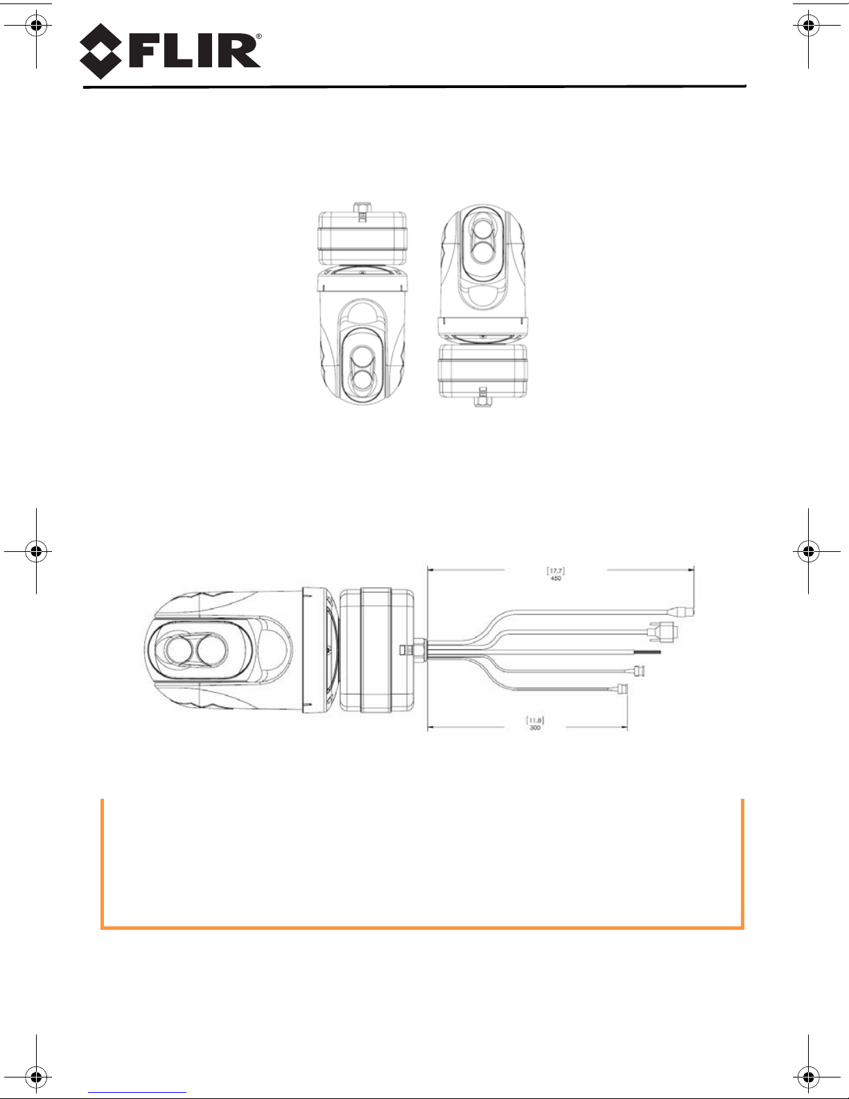
The D-Series C is shipped from the factory in one of two configurations, either
dome up or dome down, depending on the model ordered. Confirm that the
camera matches the intended installation.
All connections are made via the attached pigtail cable assembly.
• Ensure that all pigtail connections are made inside a water-tight enclosure.
Caution!
Before installing the D-Series C camera be sure to read and understand the
following documents which provide details regarding mechanical dimensions
and installation safety. These documents are available on the CD or from the
FLIR web site.
• D-Series C Installation Manual (FLIR Doc # 427-9030-01-12)
• D-Series C Interface Control Document (FLIR Doc # 427-9XXX-XX-19)
427-9030-01-28 Rev 110 Mar 2014
Page 2

Caution!
Do not disassemble the D-Series C camera. Damage to the camera can occur
as the result of careless handling or electrostatic discharge (ESD).
Prior to making any connections, ensure the power is switched off.
Camera Mounting
The camera can be attached to the mount with a single 1.5” NPT stainless
steel threaded coupler which is supplied with the camera. Optionally the
camera can also be mounted to a surface with M5 fasteners (quantity 6).
Important: Use PTFE pipe seal tape or equivalent on the coupler.
• The camera mount must support at least 11.4 kg (25 lbs).
Camera Connections
The electrical connections are made with a short pigtail cable assembly
which exits the base of the camera.
The D-Series C camera is both an analog and an IP camera.
• Analog video will require a coax cable connection to a video monitor or an analog matrix/switch.
• The IP video will require a connection to an Ethernet network switch and a
computer with the appropriate software for viewing the video stream.
Power connections
• The camera can be powered with a conventional power supply rated for 21 - 30
VAC or 21 - 30 VDC.
Wire Color VAC VDC
Red Line DC +
Black Neutral DC -
Clear Chassis Chassis
Ensure the camera is properly grounded. Failure to properly ground the camera can
lead to permanent damage to the camera. Typical to good grounding practices, the
camera chassis ground should be connected to the lowest resistance path possible.
Bench Test
Locate the FLIR Sensors Manager (FSM) disk and install the program. The default
IP address of the camera is 192.168.250.116 (static address). Set the PC address
to a compatible address (i.e. 192.168.250.1) and run the FSM program. The camera
will be automatically discovered and the video stream will appear in Video Wall 0.
Refer to the FSM User Manual for more information about the program.
Alternatively, use a web browser to connect to the camera by typing the IP address
in the URL field. Log into the camera with user name “user” and password “user”.
427-9030-01-28 Rev 110 Mar 2014
 Loading...