

Page 1
www.flir.com
D--
D
S
S
errii
e
ess
e
T
T
h
h
err
IInnssttaallllaattiioonn aanndd O
e
m
m
all
a
C
C
a
a
Oppeerraattiioonn
m
Maannuuaall
m
M
err
e
a
a
444-00001-00-10 Revision 110 Copyright © 2008 FLIR Systems, Inc. Page 1 of 33
FLIR Systems, Inc.
70 Castilian Drive
Goleta, CA 93117
Phone: 888.747.FLIR
(888.747.3547)
International: +1.805.964.9797
Page 2
FLIR Systems Inc.
70 Castilian Dr.
Goleta, CA 93117-3027
888.747.FLIR (888.747.3547)
Intl.: +1.805.964.9797
FAX 805 685-2711
www.flir.com
Document Number: 444-00001-00-10 Revision 110
Revision Number: 110
Date: November 21, 2008
Revision Date Notes
100 11/7/2008 Initial release
110 11/21/2008 Minor corrections
EXPORT RESTRICTIONS
This document is controlled to FLIR Technology Level 2. The information contained in
this document pertains to a dual use product controlled for export by the Export
Administration Regulations (EAR). FLIR trade secrets contained herein are subject to
disclosure restrictions as a matter of law. Diversion contrary to US law is prohibited. US
Department of Commerce authorization is not required prior to export or transfer to
foreign persons or parties unless otherwise prohibited.
PROPRIETARY
The data in this publication shall not be disclosed without permission and shall not be
duplicated, used, or disclosed in whole or in part except to the extent provided in any
contract of which this document is made a part. This restriction does not limit the
customer’s right to use information contained in this document if it is obtainable from
another source without restriction. The data subject to this restriction are contained in all
sheets of this document and related drawings and document specifications herein. FLIR
reserves the right to make changes to its products or specifications at any time, without
notice, in order to improve design or performance and to supply the best possible
product.
COPYRIGHT
Copyright © 2008 by FLIR Systems, Inc. All rights reserved. This publication, or any
parts thereof, may not be reproduced in any form without the express written permission
of FLIR Systems, Inc.
Pelco is a registered trademark of Pelco. Windows is a registered trademark of Microsoft Corporation.
444-00001-00-10 Revision 110 Copyright © 2008 FLIR Systems, Inc. Page 2 of 33
Page 3

Table of Contents
Legal Considerations .............................................................................................................. 4
Support ................................................................................................................................... 4
1. Warnings and Cautions .......................................................................................................... 5
2. Introduction ............................................................................................................................ 6
2.1 Advantages of Thermal Imaging ....................................................................................... 6
2.2 Pan/Tilt Mechanism .......................................................................................................... 7
2.3 Connections and Communication Protocol ....................................................................... 7
2.4 Mounting Options ............................................................................................................. 8
3. Getting Sta rted ....................................................................................................................... 9
3.1 Package Contents ............................................................................................................ 9
3.2 Installation Requirements ................................................................................................10
3.2.1 Power On Self-Test ...................................................................................................11
3.3 D-Series Camera Connections ........................................................................................12
3.4 Drop Ceiling Installation (Typical Installation) ..................................................................12
4. Removing the main camera assembly from the housing enclosure .......................................17
4.1. Disassembling the Dome ................................................................................................17
4.2. Steps to removing the camera base for installation .........................................................19
4.3. Steps to install the base cover ........................................................................................19
4.4 Hard Ceiling Installation (Pendant Mount) ........................................................................21
5. Configuration Options ...........................................................................................................23
5.1 Changing the Electronic Connections ..............................................................................23
5.2 Changing DIP Switch Settings .........................................................................................24
5.3 Changing the Pelco Address ...........................................................................................24
5.4 Changing the Baud Rate .................................................................................................24
5.5 RS-485 Termination Resistor DIP Switch ........................................................................25
5.6 Reassembling and Running Self-Check ..........................................................................25
6. Using Your D-Series Camera ................................................................................................25
6.1. IR Imaging Views ............................................................................................................25
6.2 Pelco D and Keyboard Commands ..................................................................................26
7. Troubleshooting ....................................................................................................................27
7.1 Caring for your FLIR D-Series Camera ............................................................................27
8. Performance Specifications ...................................................................................................28
8.1 FLIR D-Series Camera Dimensions .................................................................................29
8.2 Default Settings ...............................................................................................................30
8.3 Baud Rate Settings ..........................................................................................................31
9. Mounting Templates ..............................................................................................................31
9.1. Drop Ceiling Mounting Templates ...................................................................................31
9.2 Hard Ceiling Mounting Template .....................................................................................32
10. Fundamentals of Infrared ....................................................................................................33
444-00001-00-10 Revision 110 Copyright © 2008 FLIR Systems, Inc. Page 3 of 33
Page 4

List of Figures
Figure 1: Differences in imagery obtained with a standard CCTV camera (left) and the FLIR D-
Series Camera (right) ................................................................................................................. 7
Figure 2: Types of installation …………………………………………………………………………..8
Figure 3: D-Series external components ………………………………………………………………9
Figure 4: D-Series camera wiring connections ..........................................................................12
Figure 5: Installation templates (not to scale) ............................................................................14
Figure 6: Proper alignment of standoffs for installation of dome enclosure ................................16
Figure 7: Ring installation (left); D-Series Dome camera installed in ceiling (right) ....................16
Figure 8: PC Board with DIP Switch Bank .................................................................................24
Figure 9: Areas radiating heat appear brighter. .........................................................................26
Figure 10: FLIR D-Series Camera Dimensions (in mm) ............................................................30
Figure 11: Drop Ceiling Mounting Template (not to scale)... ………………………………………31
Figure 12: Hard Ceiling Mounting Template (not to scale) .........................................................32
List of Tables
Table 1: Shipping Contents ........................................................................................................ 9
Table 2: Pelco D and Keyboard Commands .............................................................................27
Table 3: Troubleshooting Guidelines .........................................................................................27
Table 4: Performance Specifications .........................................................................................29
Table 5: Address Settings .........................................................................................................30
Table 6: Baud Rate Settings .....................................................................................................31
Legal Considerations
Camera and audio surveillance may be prohibited by laws that vary from country to country.
Check the laws in your local region before using this product for surveillance purposes.
Support
If you have questions that are not covered in this manual, or need service, contact FLIR
Customer Support at (805) 964-9797 for additional information prior to returning your D-Series
Camera. In the US, you can also reach FLIR Customer Support at (888) 747-FLIR (747-3547).
444-00001-00-10 Revision 110 Copyright © 2008 FLIR Systems, Inc. Page 4 of 33
Page 5
CAUTION!
Caution
NOTE: This guide uses blue Note boxes to provide extra information on a topic.
1. Warnings and Cautions
This guide uses a yellow box with the word
hazardous situation, which, if not avoided, may result in injury or damage to the device.
1. A trained professional should install the camera in accordance with local codes and
industry-standard safe practices.
2. Disassembling the D-Series Camera for reasons other than installation, ordinary
maintenance or configuration can cause permanent damage and will void the warranty.
3. Operating the camera outside of the specified input voltage range or the specified
operating temperature range can cause permanent damage.
4. Follow the environmental guidelines included in the technical specifications required for
installation. Avoid exposure to dust and moisture.
5. Do not image extremely high intensity radiation sources, such as the sun, lasers, arc
welders, etc. This warning applies whether or not the system is powered.
6. The camera is a precision optical instrument and should not be exposed to excessive
shock and/or vibration.
7. This camera contains static-sensitive electronics and should be handled appropriately.
8. Do not install or operate the device in locations that contain flammable and/or explosive
objects.
to indicate a potentially
9. Do not try to repair the unit by yourself. FLIR Systems shall not be responsible for any
problem caused by unauthorized amendment or repairing.
10. Take great care when handling your camera optics. They are delicate and can be
damaged by improper cleaning. Clean the lens in the manner described in Section 7.1
Caring for your FLIR D-Series Camera
WARNING: All thermal imaging systems are subject to export control. Please contact FLIR
for export compliance information concerning your application or geographic area.
444-00001-00-10 Revision 110 Copyright © 2008 FLIR Systems, Inc. Page 5 of 33
.
Page 6

2. Introduction
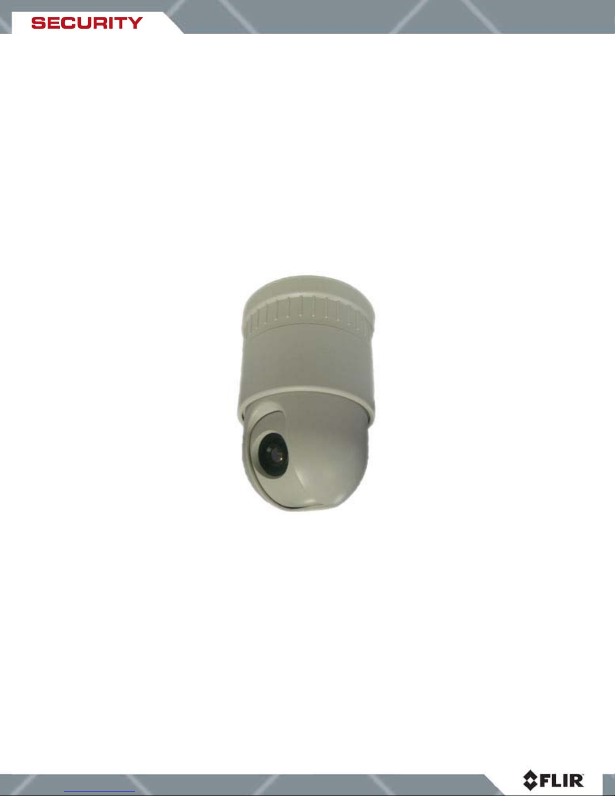
Congratulations! You have purchased one of the most important instruments you can have as
part of your security system. The D-Series Thermal Camera is a state -of-the-art thermal imaging
system especially suited to accommodate security surveillance of moving objects within a large
area.
The D-Series camera is a compact, all-in-one thermal imager with outstanding sensitivity and
image quality. T he on-focal-plane circuitry, combined with FLIR’s advanced signal processing
electronics, enables the camera to maintain excellent dynamic range and image uniformity over
a wide temperature range. The dome casing allows easy ceiling installation in a variety of indoor
locations to provide round-the-clock, high quality analog video (NTSC or PAL) with full pan, tilt
and zoom control.
Designed specifically for indoor use, the FLIR D-Series Camera is ideal for demanding security
surveillance installations at airports, railway stations, supermarkets, judicial buildings, prisons,
banks, casinos, etc.
The D-Series camera is designed for simple, intuitive installation and operation. Each camera is
based on FLIR’s widely-deployed uncooled microbolometer imaging core. All cameras include
FLIR’s advanced image processing techniques which deliver excellent contrast regardless of
scene dynamics.
2.1 Advantages of Thermal Imaging
FLIR’s powerful D-6 and D-19 indoor thermal dome cameras compliment and complete your
security camera network. They turn night into day, letting you see through smoke and in total
darkness. When the lights go out, or smoke renders conventional CCTV cameras useless, DSeries cameras still see clearly.
Originally developed for the military, thermal imaging cameras are now deployed in numerous
commercial applications where it is impractical or too expensive to use active illumination
(lights). They are perfect for wide-area surveillance in critical infrastructure or high-value
residence installations where lighting is unwelcome or impractical. The cameras also provide
improved daytime surveillance in environments where traditional CCTV security camera
performance suffers, such as in shadows, backlit scenes or through foliage.
Low-cost infrared illuminated cameras rely on near infrared (NIR) lamps to illuminate threats,
resulting in shadows, reflections, backscatter, higher power consumption, narrow areas of
illumination and much shorter ranges than passive thermal camera technology.
Unlike other night vision systems that require low amounts of light to generate an image, the DSeries Camera thermal imager needs no light at all.
The D-Series Camera is designed to be compatible with standard security systems employing
ordinary daylight cameras, with a variety of connection options available. Installation is straight
forward with standard interfaces for power, video (NTSC or PAL), and serial control (Pelco D
protocol over RS-485). The choice of lenses for the cameras (6.3mm and 19mm) allows for
short- or medium-range surveillance capability.
444-00001-00-10 Revision 110 Copyright © 2008 FLIR Systems, Inc. Page 6 of 33
Page 7
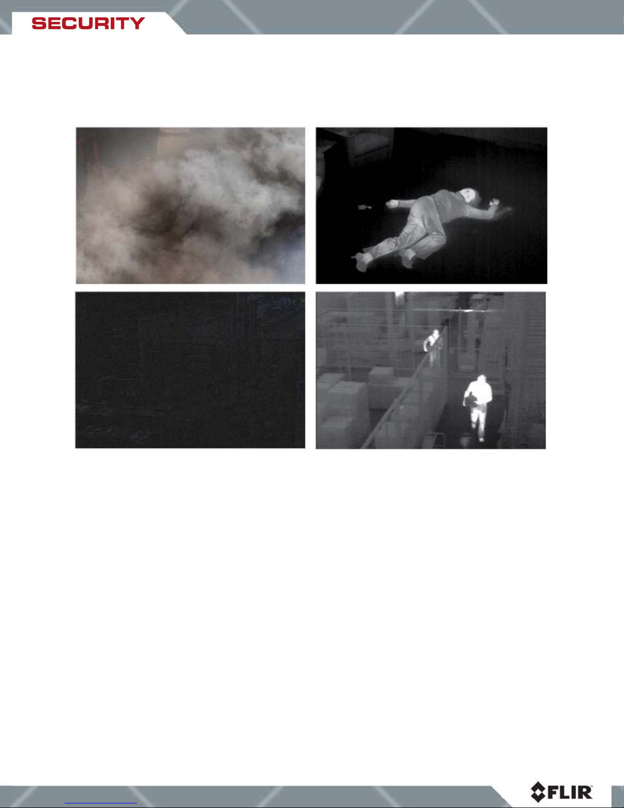
The D-Series Camera features a wide field of view and is capable of providing an image even in
absolute darkness. Figure 1 shows the limitations of images obtained with a standard CCTV
camera and the advantages provided by the D-Series camera in extreme conditions.
Figure 1: Differences in imagery obtained with a standard CCTV camera (left) and the FLIR DSeries Camera (right)
2.2 Pan/Tilt Mechanism
The FLIR D-Series Camera provides a continuous 360° pan operation and a 90° tilt operation
with automatic flip to provide complete 180° tilt coverage. The pan and tilt speeds range from
0.5° per second to 100° per second. To accommodate typical security surveillance operations,
up to 80 preset locations can be configured on the camera. The camera can also be set to
continuously auto scan between two positions or up to 200 points can be set in a repeating
pattern.
2.3 Connections and Communication Protocol
The D-Series camera provides standard video format output via a BNC connector. The camera
is controlled using the Pelco-D protocol over RS485 serial communications, and is powered
using a 24V AC power supply. The camera is provided with a 6 foot bundled cable system that
includes the connections for video, power and serial control.
444-00001-00-10 Revision 110 Copyright © 2008 FLIR Systems, Inc. Page 7 of 33
Page 8
standard safe practices.
Any device that communicates with the Pelco-D protocol can be used as a control unit, including
a commonly-used joystick keyboard such as the Pelco KBD300A or a more sophisticated device
such as an IP-encoder with serial control. The control unit can be used to operate the following
functions or features:
• Pan/Tilt operation
• Set or activate preset location
• Set or Initiate auto scan or pattern scan sequence
• Zoom (2x digital zoom, available on D-19 camera only)
• Video palette (white hot by default, black hot and rainbow palettes available also)
• Scene setting (user-selectable automatic gain control settings)
• Invert Image
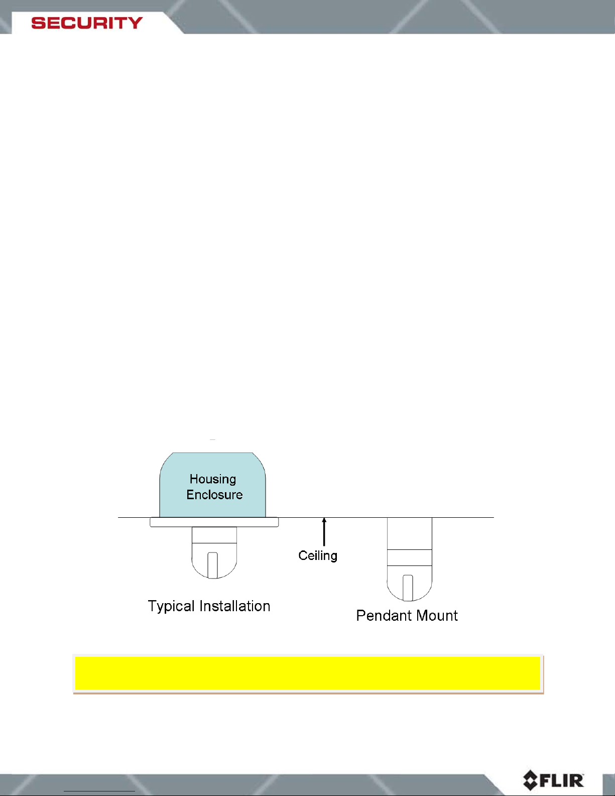
2.4 Mounting Options
The FLIR Thermal Camera is designed to be mounted in the ceiling. The camera is ordinarily
mounted with the main camera assembly above the ceiling, with only the camera dome and trim
ring exposed. During the installation, the main camera assembly is temporarily removed from
the camera housing enclosure. The housing enclosure is installed in the ceiling, then the
camera body is reinstalled in the housing, and finally the trim ring is installed. FLIR recommends
using a mounting board and chain when installing in a drop ceiling.
Alternatively, for locations where there is insufficient clearance above the ceiling, the camera
can be installed hanging from the ceiling (known as a “pendant” mount), in which case the entire
camera body (minus the housing enclosure) hangs below the ceiling. The housing enclosure is
not used with this type of installation. See sections 3 and 4 for detailed installation instructions.
CAUTION! The camera should be installed in accordance with local codes and industry-
444-00001-00-10 Revision 110 Copyright © 2008 FLIR Systems, Inc. Page 8 of 33
Figure 2: Types of installation
Page 9
IR Imager (Photon)
Electrical Connections
3. Getting Started
3.1 Package Contents
Refer to the Shipping Check List that is shipped with each camera for a description of the parts
and components that are included with the camera. If there is any discrepancy between the list
and the contents of your shipment, please contact FLIR Systems Customer Support
immediately using the contact information at the front of this manual. Please retain the original
shipping container and packing materials in case the camera possibly needs to be shipped in
the future.
Item Quantity
D-Series Camera with electrical connectors attached
(Figure 3)
Self-Tapping Screw M4×30 with wall anchors 3
Mounting template 1
Pan head screws with cross recessed M4×15 4
Flat Washer • 4 4
Table 1: Shipping Contents
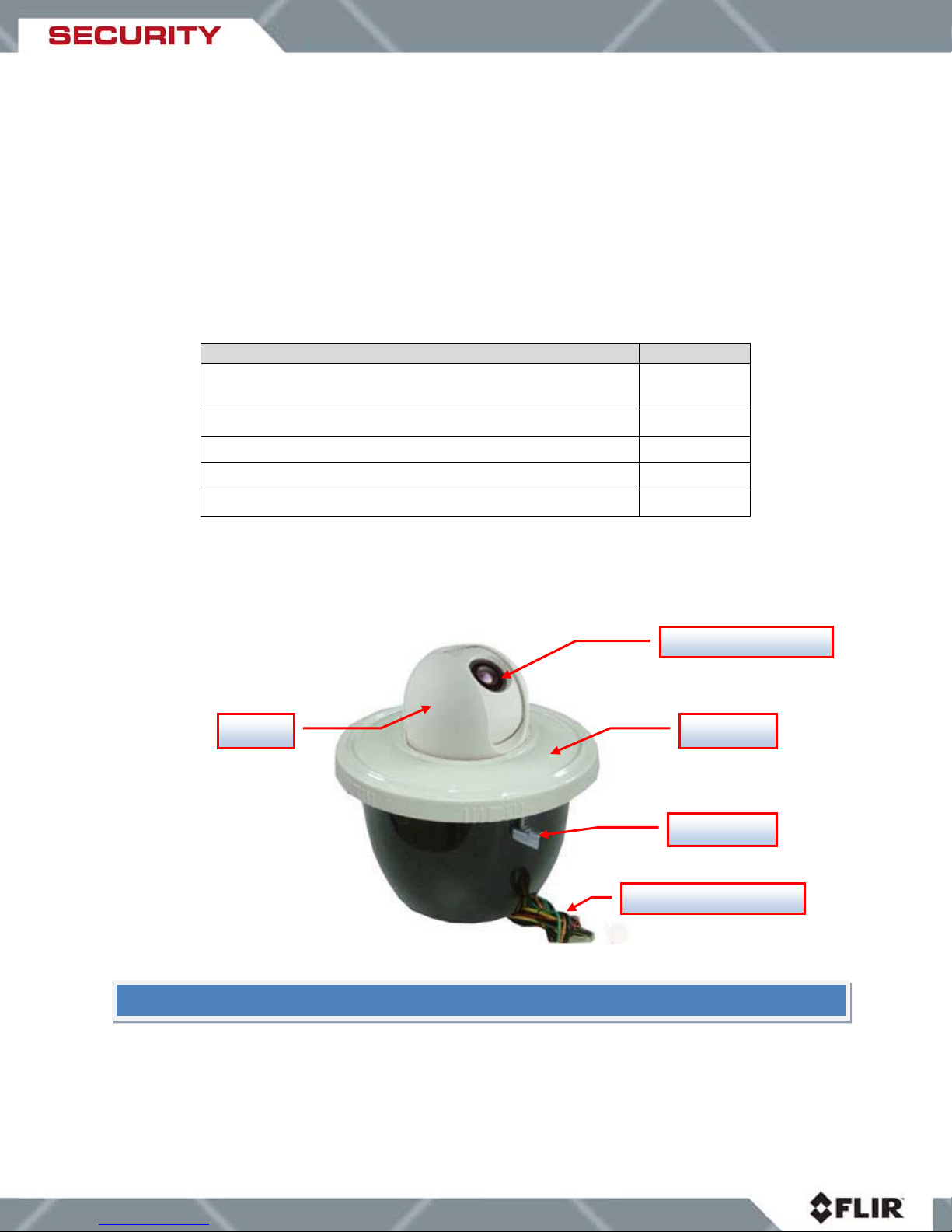
Figure 3 illustrates the outer parts of the FLIR D-Series Camera:
1
Dome
Trim ring
Spring Clip
Figure 3: D-Series external components
NOTE: if any specified materials are missing or damaged, please contact your FLIR dealer
444-00001-00-10 Revision 110 Copyright © 2008 FLIR Systems, Inc. Page 9 of 33
Page 10
CAUTION
CAUTION
3.2 Installation Requirements
Generally, some level of disassembly and reassembly is necessary during the installation
process. If it is necessary to change any of the default settings (for example, the Pelco
address), refer to section
camera assembly prior to installation and access the configuration DIP switches. It is also
necessary to separate the base from the main camera assembly if the cables that are provided
with the camera are to be replaced with other cables.
In order to get familiar with the camer a installation and operation, it may be wise to make the
appropriate connections to the camera while the camera is on a test bench prior to doing the
actual installation. Observe the initial power-on self-test before you install the camera into the
ceiling and ensure that it is supplying video to a monitor and responding to the joystick
controller. The wiring connections are described below.
Shielded Twisted Pair (STP) wiring is recommended for the RS485 cable to avoid problems with
performance, communication or video noise. The shielding wire must be grounded.
! The Dome Camera should be installed by a certified CCTV installer who has
experience working with CCTV system component installation, operation and repair.
Incorrect installation could void your warranty.
4.1. Disassembling the Dome for information on how to take apart the
! The Dome Camera is intended to be mounted in the ceiling with the camera
facing away from the mounting plane. Any other type of installation is not appropriate and
could result in undesirable operation, which will void the warranty.
Tools/Materials Needed:
• Small slotted screw driver
• Phillips screw driver
• Soft lens cloth
• Wire nuts
• Safety chain or cable for in-ceiling installa tion
• Appropriate tool(s) for cutting hole in ceiling
Safety Requirements - the ceiling should meet the following safety requirements:
1. The installation site must have enough clearance to allow for the necessary freedom of
travel for pan and tilt operation over the full range. Refer to the
Specifications section for
specific dimensions.
2. The installation site must be stable and sturdy enough to hold the camera during the
continuous pan and tilt movement.
3. The installation materials must be capable of supporting well in excess of the weight of
the product and accessories. FLIR Systems, Inc. is not responsible for damage or injury
that results from an improperly installed camera.
444-00001-00-10 Revision 110 Copyright © 2008 FLIR Systems, Inc. Page 10 of 33
Page 11

insufficient.
NOTE
The D-Series camera has grounding and surge protection to provide further immunity from high
current transients that can occur in installations that are subject to electrical storms and/or
nearby lightning events. In order to ensure CE and FCC compliance as well as to protect
against these high current events, installers are required to provide an earth connection to
the camera.
NOTE: A ground connection to the exterior of the camera (for example, to the spring clip) is
Caution! The camera must be installed according to industry-standard practices and local
electrical codes. Failure to properly connect the camera to ground could result in damage to
the camera and possible bodily injury.
3.2.1 Power On Self-Test
The D-Series Camera goes through a self-test process after power on. T he camera will tilt up to
the top near the trim ring and the dome will perform a full rotation. The self-test is complete
when the camera tilts to the home position. Although the unit will produce a video signal
during the self-test, it is not possible to operate the camera (pan/tilt or other operations)
until the self-test process is complete.
: if you encounter problems with the self-check process, please refer to the
Troubleshooting section for recommendations.
444-00001-00-10 Revision 110 Copyright © 2008 FLIR Systems, Inc. Page 11 of 33
Page 12

3.3 D-Series Camera Con n ecti on s
Figure 4: D-Series Camera wiring connections
WARNING: The Green/Yellow Gr ound wire must be properly connected in order for the
camera to operate properly.
3.4 Drop Ceiling Installation (Typical Installation)
WARNING! Make sure the Dome Camera and any other related equipment is powered off
during installation.
The FLIR Thermal Camera is designed to be mounted on the ceiling. A typical installation uses
the supplied housing enclosure, which conceals the main body of the camera in the ceiling,
showing only the camera dome. Alternatively, the camera can be installed hanging from the
444-00001-00-10 Revision 110 Copyright © 2008 FLIR Systems, Inc. Page 12 of 33
Page 13

Step 1
ceiling (“pendant” installation), in which case the entire camera body (minus the housing
enclosure mount) hang from the ceiling in plain view. Which mounting type you use depends on
your specific security needs.
When cutting the hole for the camera in the ceiling, be sure to follow the template provided
carefully. If the hole is cut too large or imprecisely, the camera will not fit snugly in the hole and
it will be difficult to secure the camera safely.
NOTE: It may be useful to have another person hold the camera in place while tightening the
spring clips.
Cut an approximately 9 ½ “ diameter hole in the surface where the dome is to be
mounted using the template provided with the SR-Series camera. A sketch (not to
scale) is shown in Figure 5.
Cutouts
444-00001-00-10 Revision 110 Copyright © 2008 FLIR Systems, Inc. Page 13 of 33
Page 14

In-ceiling mount template
Pendant mount template
Step 2
Trim ring
Step 3
Figure 5: Installation templates (not to scale)
Turn the trim ring on the unit counter-clockwise to remove it, as shown below.
Secure the mounting board and security chain to the bottom of the dome.
444-00001-00-10 Revision 110 Copyright © 2008 FLIR Systems, Inc. Page 14 of 33
Page 15

Mounting Board
Safety Chain/Cable
Spring Clip
Screw
Step 4
Insert the dome into the ceiling hole, making sure you align the retaining clips with the
cutouts on the mounting board.
Upper Dome
Ceiling Tile
Rotate the dome clockwise until the large plastic standoff falls into the center of the
Step 5
cutout and the two small plastic standoffs surrounding the mounting screw rest firmly
against the ceiling board (they should be flush with the ceiling board).
444-00001-00-10 Revision 110 Copyright © 2008 FLIR Systems, Inc. Page 15 of 33
Page 16

Step 6
Mounting screw
Board Cutout
Large plastic standoff
Small plastic standoffs
Step 7
Figure 6: Proper alignment of standoffs for installation of dome enclosure
Tighten the mounting screws until the spring clips make contact with the back of the
mounting board and are secure. Attach the mounting board onto a secure beam or
any other secure platform.
Slide the trim ring into the slots on the dome edge and turn clockwise to tighten it.
Figure 7: Ring installation (left); D-Se ries Dome camera installed in ceiling (right)
444-00001-00-10 Revision 110 Copyright © 2008 FLIR Systems, Inc. Page 16 of 33
Page 17

Trim ring
4. Removing the main camera assembly from the housing
enclosure
With certain installations, including a pendant mount installation, it may be necessary to remove
the camera from the housing enclosure. It may also be necessary to remove the base from the
main camera assembly so the DIP switches are accessible (for example, to change the Pelco
address). The instructions for these disassembly steps are provided below.
4.1. Disassembling the Dome
The PC board and electrical interface board are located within the inner dome cylinder. To
disassemble the dome, follow these steps:
Step 1
Step 2
If the power is on, power off the unit.
Turn the trim ring counter-clockwise and remove it from the unit.
Step 3
444-00001-00-10 Revision 110 Copyright © 2008 FLIR Systems, Inc. Page 17 of 33
Reach inside and lift the catch on the bottom of the inner cylinder. Push down on
the cylinder and turn the cylinder counter-clockwise to release it, then pull the
cylinder up.
Page 18

Catch
Cylinder bottom
Safety cable
Ribbon cable
Step 4
When you lift the inner cylinder, the bottom of the cylinder, which contains the
electronic interface board, remains attached to the dome bottom. The ribbon
cable and safety cable connect the two parts.
NOTE: To make it easier, you may want to disconnect the cables and completely remove the
inner cylinder. The cylinder bottom is attached to the dome by four screws on the bottom of
the dome. You may remove it as well. A safety cable attaches the cylinder to the cylinder
bottom and is designed to keep the cylinder from falling off if the maintenance person were to
accidentally drop it.
444-00001-00-10 Revision 110 Copyright © 2008 FLIR Systems, Inc. Page 18 of 33
Page 19

4.2. Steps to removing the camera base for installation
1. Hold the camera upside down firmly. You may need someone else to hold the camera
housing at this point to keep it from turning.
2. Pull the tab out, being careful not to break it, while at the same time pushing down on
the base. Do not use a screwdriver or any other metal tool to pull the tab out or you may
break it.
2 and 3: Push
down and turn
base counter
clockwise
1. Pull tab out
and hold
3. While pushing the base down and holding the tab out, rotate the base clockwise. This
will release the locking mechanism and you can now pull out the base cover.
4.3. Steps to install the base cover
1. To install the base, align the cutout on the base with the pull out tab
444-00001-00-10 Revision 110 Copyright © 2008 FLIR Systems, Inc. Page 19 of 33
Page 20

2. Turn the base clockwise and make sure the locking mechanism engages (you will hear a
clicking sound when the locking mechanism sets in place.
444-00001-00-10 Revision 110 Copyright © 2008 FLIR Systems, Inc. Page 20 of 33
Page 21

CAUTION!
Step 2
Step 3
Mounting the camera without the locking mechanism properly engaged may
result in the camera falling from its base. Damage to the camera may occur!
4.4 Hard Ceiling Installation (Pendant Mount)
Step 1
Step 1
Cut a 2
template provided with the camera (see sketch in Figure 4). Drill holes for wall
anchors.
Wall anchor holes
3/8
” •diameter hole in the surface where the Dome is to be mounted using the
Attach the base to the ceiling using the three screws and wall anchors provided.
The wires go up through the central hole in the camera base.
Ceiling
mounting holes
Attach the safety cable and ribbon cable.
444-00001-00-10 Revision 110 Copyright © 2008 FLIR Systems, Inc. Page 21 of 33
Page 22

Step 4
Ribbon cable
Safety cable
Attach the dome to the base using the locking mechanism. Make sure the locking
mechanism engages, as indicated by a clicking sound. Failure to properly engage
the locking mechanism may cause the dome to fall from the base, resulting in
damage to the dome and base, and possible personal injury.
444-00001-00-10 Revision 110 Copyright © 2008 FLIR Systems, Inc. Page 22 of 33
Page 23

1 2 6
3
4
5
5. Configuration Options
The D-Series Camera comes with defaults set (see Section 5.4: Default Settings). However, you
can make the following modifications to the FLIR D-Series Camera:
• Change the electronic wiring connections
• Change the dip switch settings on the PC board
To make the changes, you must first disassemble the Dome as described in
should be done by a certified CCTV person only.
5.1 Changing the Electronic Connections
The electronic connections may be changed on the electronic interface as shown below:
Section 4. This
1. Welding point of coaxial cable
2. Fixing point of coaxial cable
3. RS485 Terminal (Left to right: B, A, GND)
4. 10-plug connector for ribbon cable
5. 24VAC Terminal (Left to right: AC24V, AC24V, SAFE-GND)
6. 24VAC (Spare use)
444-00001-00-10 Revision 110 Copyright © 2008 FLIR Systems, Inc. Page 23 of 33
Page 24

Connect the external cables to the electronic interface according to the following guidelines:
Power RS485 Video
Function
AC24V B- A+ GND V+ V-
GND
Cable
Color
Red Yellow Blue Red Black Core
Screen
Olivine
Shield
5.2 Changing DIP Switch Settings
If needed, you may change the dip switch settings on the PC board. Figure 10 shows the
location of the DIP switches:
The default settings are listed on Section 5.4 default Settings.
5.3 Changing the Pelco Address
The Pelco address (001-255) is set using DIP switch S2. See
5.4 Changing the Baud Rate
The baud rate for communication with the D-Seri es camera using the Pelco-D protocol can be
set to 2400, 4800, 9600, or 19200. The factory default is 2400, which is the baud rate used by
444-00001-00-10 Revision 110 Copyright © 2008 FLIR Systems, Inc. Page 24 of 33
Figure 8: PC Board with DIP Switch Bank
section 8.2 for details.
Page 25

for recommendations.
the Pelco 300 keyboard. Use Switch S3, bits 5 and 6 to change this setting as shown in section
8.3 Baud Rate Settings.
5.5 RS-485 Termination Resistor DIP Switch
This is switch 8 on DIP switch S3. The switch is needed for when multiple cameras are wired in
a true RS485 "network", where the Pelco KBD (or similar controller device) uses addressable
commands from one access point. This switch needs to be set to the "On" position for the last
Thermal Dome in the chain. While a small network may work even if this switch is not set to
“On, the system may be unstable and reliability compromised.
For the best reliability, the last camera (certainly for a large installation) should have this RS485
switch set to "On" and the remaining cameras have the switch set to "Off". The default setting of
this switch is “Off”.
5.6 Reassembling and Running Self-Check
Before installation, reassemble the dome and run the self-check.
1. Reconnect the ribbon cable and white cable between the PC board and electronic
interface board.
2. Insert the cylinder into the bottom section and turn clockwise until you hear a click. The
click indicates the cylinder is locked in place.
3. Slide the trim ring into the slots on the Dome edge and turn clockwise to tighten.
4. Before you install the camera into the ceiling, connect the power, video, and serial
cables to your security network and run the self-check.
NOTE: if you encounter a problem or malfunction please refer to the Troubleshooting section
6. Using Your D-Series Camera
6.1. IR Imaging Views
The D-Series Camera is easy to use, but you should take a moment to carefully read this
section so you fully understand what you are seeing on your display. While the imagery you will
see on the monitor may look like black and white daylight video, it isn’t! A few tips on how to
interpret some of the imagery will help you to make the most of your system.
Turn on the camera using the on/off switch on the power supply. After the self-check, you can
use the joystick to control the pan and tilt features of the camera. Controlling the camera’s
direction becomes intuitive after a few minutes of experimenting. The camera automatically
adjusts to changing scene conditions so no additional adjustments of contrast or brightness are
necessary.
The thermal imager inside the camera does not sense light like conventional cameras; it senses
heat or temperature differences. As you experiment with the system during daylight and
444-00001-00-10 Revision 110 Copyright © 2008 FLIR Systems, Inc. Page 25 of 33
Page 26

21 Preset
1 Aux On
Black Hot LUT
Default Settings
Default, Not Inverted
nighttime operation, you will notice differences in the “picture quality”; this is normal. The
camera senses small “differences” in apparent radiation from the objects in view and displays
them as either white (or lighter shades of gray) for warmer objects, and black (or darker shades
of gray) for colder objects. This is why you will see areas of an object or person that appear
white while the rest of the object or person may appear dark (or cool).
Figure 9: Areas radiating heat appear brighter.
Scenes with familiar objects will be easy to interpret with some experience. The camera
automatically optimizes the image to provide you with the best contrast in most conditions.
6.2 Pelco D and Keyboard Commands
The following table shows the commands available to the Thermal Dome. No other commands
are available, and the camera operates in slave mode only. It recognizes and acts on the
commands received immediately but it does not communicate in any way back to the host or
keyboard. Note that the Pelco Commands can either be initiated over the RS-485 command
wires directly from a customer host system, or from the Pelco keyboard by entering “command
number”, then pressing the Preset button.
Pelco Command Keyboard
Command
11 Preset 1 Aux Off White Hot LUT
22 Preset 2 Aux On Set to 2X Zoom Also accessed by rotating
12 Preset 2 Aux Off Set to 1X Zoom Also accessed by rotating
23 Preset 3 Aux On Toggle AGC Toggles through 7 AGC
13 Preset 3 Aux Off Invert Image Repeat to Non-Invert
24 Preset 4 Aux On Set Power-up
14 Preset 4 Aux Off Restore Factory
Thermal Dome
Function
Settings
Comment
the joystick
counterclockwise
the joystick clockwise
settings
White H ot, Zoom 1X, AGC
444-00001-00-10 Revision 110 Copyright © 2008 FLIR Systems, Inc. Page 26 of 33
Page 27

Hot
16 – 20 Prese t
5 Aux On
Reserved
Move joystick to stop
1 – 10 Prese t
----------
Available for use
Hold Preset for >3 seconds
Symptoms
Possible Reasons
Recommendations
connection
Not enough power
Change power supply
Wrong connection
Reconnect
switcher or wrong operation
with manual
of camera serial number and
15 Preset 5 Aux Off Toggle LUT
25 – 29 Prese t 6 – 9 Aux On/Off Reserved
92 Preset ---------- Set Auto Scan Left Hold Preset for >3 seconds
93 Preset ---------- Set Auto Scan Right Hold Preset for >3 seconds
99 Preset ---------- Start Auto Scan Tilt is not set, does not
30 – 52 Prese t ---------- Available for use Hold Preset for >3 seconds
Pattern ---------- Up to 200
programmable
positions
Table 2: Pelco D and Keyboard Commands
Color, White Hot, Black
change
Hold Pattern button for >3
seconds, then move to
desired positions, ACK to
end pattern
7. Troubleshooting
No self-checking or/and
image after power on
No self-checking
or with noise
No image after selfchecking
Incorrect power supply
Power supply problem Change power supply
Mechanical failure Contact FLIR technical support
Bad connection Check connections
Wrong connection of video
Check power supply connections
Connect and operate in accordance
No operation after selfchecking
Image lost during dome
operation
Image instability
No display of camera
chosen
Wrong connection of control
wires
Wrong setup of address,
protocol or baud rate
Not enough power Replace power supply
Bad connection Check connections
Video switcher or electronic
malfunction
Wrong connection position
video switcher
Table 3: Troubleshooting Guidelines
Reconnect
Re-setup
Contact FLIR Technical Support
Reconnection to camera serial
number
7.1 Caring for your FLIR D-Series Camera
For lens cleaning use the following materials:
• Optical-grade tissue (e.g., Edmund Industrial Optics part number 52105 or any similar
product)
• Pure water (de-ionized or other)
444-00001-00-10 Revision 110 Copyright © 2008 FLIR Systems, Inc. Page 27 of 33
Page 28

Outputs
• Isopropyl alcohol (IPA)
Cleaning Procedure:
1. Saturate a piece of the lens tissue with the water and drape it over the lens. Let the
surface tension of the water pull the tissue onto the lens surface; then drag the tissue
across the lens surface. Repeat several times with different pieces of tissue.
2. Repeat the same procedure using IPA instead of water. Drag the final piece of tissue
over the lens several times to prevent pooling, which could leave a residue on the lens.
8. Performance Specifications
Performance
Camera Type Uncooled LWIR Thermal Imager
Sensor Type 324x256 Vox Microbolometer
Pixel Si ze 38 µm
Spectral Band 7.5 – 13.5 µm
Performance < 85mK NE dT at f/1.6
Movement Pan: 0° – 360° Continuous Tilt: 0° – 90° (180° with flip)
Speed Pan: 0.5° – 100°/S Tilt: 0.5° – 100°/S
Max. Preset Speed 100°/S
Preset Point 80
Auto Scan 1 Route
Patterns 1 Route, 200 Instructions
Analog Video
Power
Input Voltage 24VAC±25%
Power Consumption • 20W
Operation
Image Control Invert, 2x digital zoom, AGC
Time to I mage ~2 seconds
Environmental
Storage Temperature -40 – +85 °C external temp
Environment in-ceiling, indoor only
Humidity only non-condensing
Scene Temp Range To 150 °C standard
Shock 70g shock pulse, 11ms half-sine profile
Vibration 4.3 g ms random vibration for 8 hours (three axes)
Operational Temperature -100 C to +500 C
Default Settings
Baud Rate 2400 Baud
Pelco ID Address 01
NTSC @ 30 Hz
PAL @ 25 Hz (optional)
9 Hz option for export (factory set)
444-00001-00-10 Revision 110 Copyright © 2008 FLIR Systems, Inc. Page 28 of 33
Page 29

Shipping Dimensions
Size 15” x 15” x 19” (38 cm x 38 cm x 48 cm)
Weight 10.7 lbs (4.86 kg)
Table 4: Performance Specifications
8.1 FLIR D-Series Camera Dimensions
444-00001-00-10 Revision 110 Copyright © 2008 FLIR Systems, Inc. Page 29 of 33
Page 30

NOTE
Figure 10: FLIR D-Series Camera Dimensions (in mm)
8.2 Default Settings
,
The FLIR D-Series Camera comes with a default address of 001 (Table 6), a Baud rate of 2400,
and default Pelco-D auxiliary command settings (Table 2).
: If you decide to change the settings, FLIR recommends making the change before
installation.
Address 1 2 3 4 5 6 7 8
001
002 OFF ON OFF OFF OFF OFF OFF OFF
003 ON ON OFF OFF OFF OFF OFF OFF
004 OFF OFF ON OFF OFF OFF OFF OFF
005
006 OFF ON ON OFF OFF OFF OFF OFF
ON
ON
OFF OFF OFF OFF OFF OFF OFF
OFF ON OFF OFF OFF OFF OFF
007 ON ON ON OFF OFF OFF OFF OFF
008 OFF OFF OFF ON OFF OFF OFF OFF
…… …………………………………………………………………
254 OFF ON ON ON ON ON ON ON
255 ON ON ON ON ON ON ON ON
444-00001-00-10 Revision 110 Copyright © 2008 FLIR Systems, Inc. Page 30 of 33
Table 5: Address Settings
Page 31

On
On
19200
installation are provided with the SR-Series Camera.
8.3 Baud Rate Settings
The FLIR D-Series Camera comes with the Baud rate set to 2400. Use the table below to set
the Baud rate using S3, bits 5 and 6.
5 6 Baud Rate
Off Off 2400
On Off 4800
Off On 9600
Table 6: Baud Rate Settings
9. Mounting Templates
9.1. Drop Ceiling Mounting Templates
NOTE: for your convenience, full size templates for both drop ceiling and hard ceiling
Figure 11: Drop Ceiling Mounting Template (not to scale)
444-00001-00-10 Revision 110 Copyright © 2008 FLIR Systems, Inc. Page 31 of 33
Page 32

9.2 Hard Ceiling Mounting Template
Figure 12: Hard Ceiling Mounting Template (not to sc ale)
444-00001-00-10 Revision 110 Copyright © 2008 FLIR Systems, Inc. Page 32 of 33
Page 33

10. Fundamentals of Infrared
444-00001-00-10 Revision 110 Copyright © 2008 FLIR Systems, Inc. Page 33 of 33
 Loading...