


FLIR CM42, CM44, CM46 User Manual
USER MANUAL
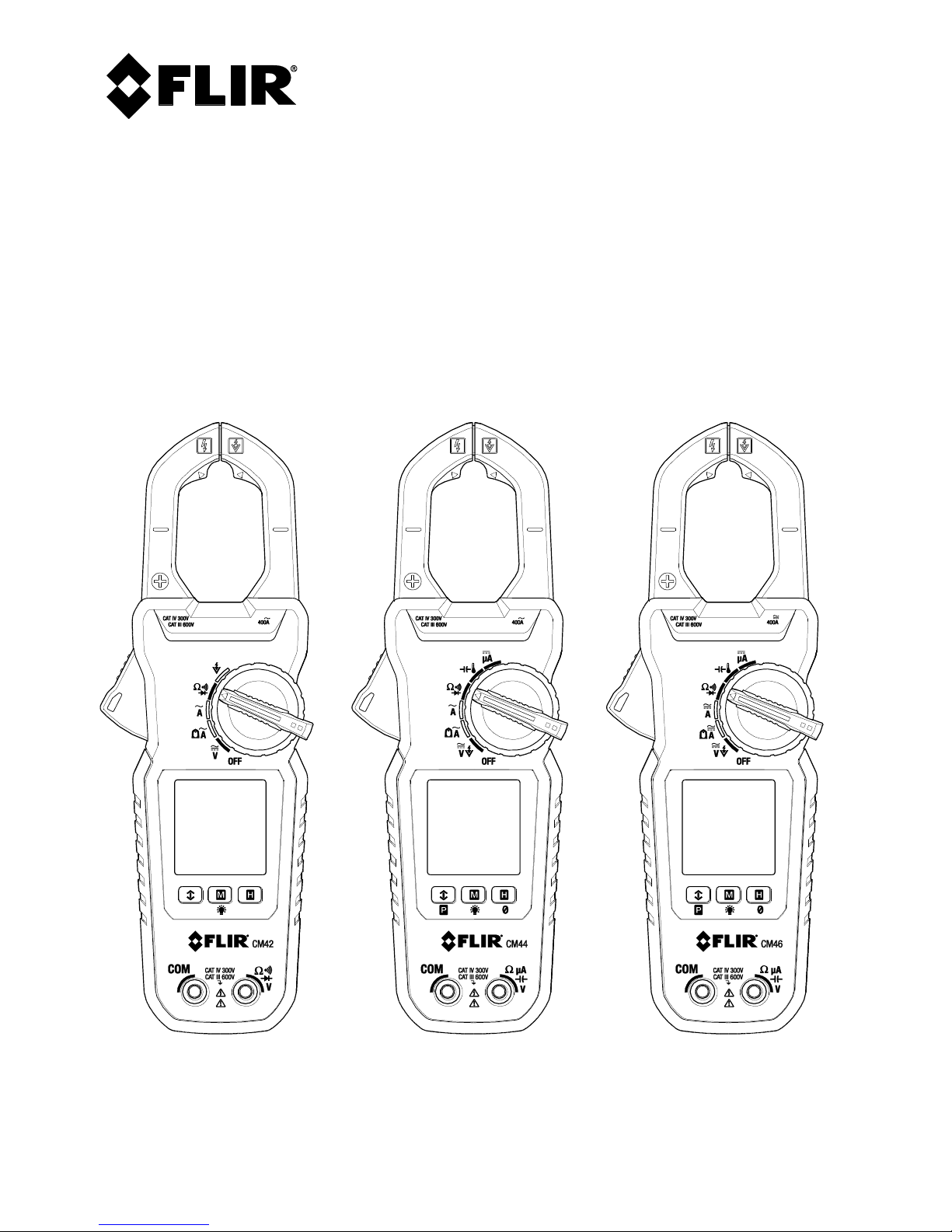
FLIR True RMS 400A Clamp Meter Series
Models CM42, CM44, and CM46

FLIR CM4x USER MANUAL Document ID: CM4x-en-US_AA
2
Table of Contents
1. DISCLAIMERS 4
1.1 Copyright 4
1.2 Quality Assurance 4
1.3 Documentation 4
1.4 Disposal of Electronic Waste 4
2. SAFETY 5
3. INTRODUCTION 7
4. DESCRIPTION 8
4.1 Meter Parts 8
4.2 Function Switch Positions 9
4.3 Function Buttons 10
4.4 Display Icons and Indicators 10
5. OPERATION 12
5.1 Powering the Meter 12
5.2 Intelligent Auto Power OFF (APO) feature 12
5.3 Auto Range 12
5.4 Out-of-range Warning 12
5.5 Voltage Measurements 13
5.6 Electric Field (EF) Detection 14
5.7 Standard Current Clamp Measurements 15
5.8 Low Current Accu-TipTM Clamp Measurements 17
5.9 DC A Current Test Lead Measurements (CM44 and CM46) 18
5.10 Resistance Measurements 19
5.11 Continuity Tests 19
5.12 Capacitance Measurements (CM44 and CM46) 20
5.13 Temperature Measurements (CM44 and CM46) 21
5.14 Diode Tests 22
5.15 Relative / DC Zero Modes (CM44 and CM46) 23
5.16 MIN/MAX/AVG Recording 23

FLIR CM4x USER MANUAL Document ID: CM4x-en-US_AA
3
5.17 VFD Mode (low pass filter) 23
5.18 Display Hold Function 24
5.19 Display Backlighting 24
5.20 PEAK Mode (CM44 and CM46) 24
6. MAINTENANCE 25
6.1 Troubleshooting Tips 25
6.2 Accuracy and Calibration 25
6.3 Cleaning and Storage 25
6.4 Battery Replacement 25
7. SPECIFICATIONS 26
7.1 General specifications 26
7.2 Electrical specifications 28
8. TECHNICAL SUPPORT 31
9. WARRANTY 32
FLIR CM4x USER MANUAL Document ID: CM4x-en-US_AA
4
1. Disclaimers
1.1 Copyright
© 2016, FLIR Systems, Inc., All rights reserved worldwide. No parts of the software
including source code may be reproduced, transmitted, transcribed or translated into
any language or computer language in any form or by any means, electronic, magnetic,
optical, manual or otherwise, without the prior written permission of FLIR Systems.
The documentation must not, in whole or part, be copied, photocopied, reproduced,
translated or transmitted to any electronic medium or machine readable form without
prior consent, in writing, from FLIR Systems.
Names and marks appearing on the products herein are either registered trademarks or
trademarks of FLIR Systems and/or its subsidiaries. All other trademarks, trade names or
company names referenced herein are used for identification only and are the property
of their respective owners.
1.2 Quality Assurance
The Quality Management System under which these products are developed and
manufactured has been certified in accordance with the ISO 9001 standard.
FLIR Systems is committed to a policy of continuous development; therefore, we reserve
the right to make changes and improvements on any of the products without prior
notice.
1.3 Documentation
To access the latest manuals and notifications, go to the Download tab at:
http://support.flir.com. It only takes a few minutes to register online. In the download
area you will also find the latest releases of manuals for our other products, as well as
manuals for our historical and obsolete products.
1.4 Disposal of Electronic Waste
As with most electronic products, this equipment must be disposed of in an
environmentally friendly way, and in accordance with existing regulations
for electronic waste.
Please contact your FLIR Systems representative for more details.
FLIR CM4x USER MANUAL Document ID: CM4x-en-US_AA
5
2. Safety
SAFETY NOTES
This user manual contains information and warnings that must be followed for operating the
instrument safely and maintaining the instrument in a safe operating condition. If the instrument is
used in a manner not specified by the manufacturer, the protection provided by the instrument
may be impaired.
The meter protection rating, against the users, is double insulation per UL/IEC/EN61010-1 Ed. 3.0,
IEC/EN61010-2-033 Ed. 1.0, CAN/CSA C22.2 No. 61010-1 Ed. 3.0, IEC/EN61010-2-032 Ed. 3.0 &
IEC/EN61010-031 Ed. 1.1: Measurement Category III 600V & Category IV 300V AC & DC.
BRIEF INFORMATION ABOUT MEASUREMENT CATEGORIES
Measurement Category IV is applicable to test and measuring circuits connected at the source of the building’s
low-voltage MAINS installation. Examples are measurements on devices installed before the main fuse or
circuit breaker in the building installation.
Measurement Category III is applicable to test and measuring circuits connected to the distribution part of the
building’s low-voltage MAINS installation. Examples are measurements on distribution boards (including
secondary meters), circuit-breakers, wiring, including cables, bus-bars, junction boxes, switches, socket-outlets
in the fixed installation, and equipment for industrial use and some other equipment such as stationary motors
with permanent connection to the fixed installation.
Measurement Category II is applicable to test and measuring circuits connected directly to utilization points
(socket outlets and similar points) of the low-voltage MAINS installation. Examples are measurements on
MAINS CIRCUITS of household appliances, portable tools and similar equipment.
TERMS USED IN THIS MANUAL
WARNING Identifies conditions and actions that could result in serious injury or even death
to the user.
CAUTION Identifies conditions and actions that could cause damage or malfunction in the
instrument.
WARNING STATEMENTS
To reduce the risk of fire or electric shock, do not expose this product to rain or moisture. The
meter is intended only for indoor use.
To avoid electrical shock hazard, observe the proper safety precautions when working with
voltages above 60 VDC or 30 VAC rms. These voltage levels pose a potential shock hazard to the
user. Before and after hazardous voltage measurements, test the voltage function on a known
source such as line voltage to determine proper meter functioning.
Keep hands/fingers behind the hand/finger barriers (of the meter and the test leads) during
measurement. Inspect test leads, connectors, and probes for damaged insulation or exposed metal
FLIR CM4x USER MANUAL Document ID: CM4x-en-US_AA
6
before using the instrument. If any defects are found, replace them immediately. Use only the test
leads provided with the equipment (or UL Listed Probe Assemblies rated CAT III 600V or better).
The accompanied test probe assembly meets UL/IEC/EN61010-031 Ed. 1.1 to the same meter
ratings or better. IEC 61010-031 requires exposed conductive test probe tips to be ≤ 4mm for CAT
III & CAT IV ratings. Refer to the category markings on your probe assemblies as well as on the addon accessories (detachable Caps or Alligator Clips, etc.), if any, for applicable rating changes.
This Clamp meter is designed to be clamped around or removed from un-insulated, hazardous live
conductors. Nonetheless, individual protective equipment must be used when hazardous live parts
in the installation, where the measurement is to be carried out, could be accessible.
Remove test leads from meter before taking clamp measurements.
CAUTION STATEMENTS
Disconnect the test leads from the test points before changing meter functions.
Disconnect the test leads from the meter before taking clamp measurements.
Do not use the device for a procedure that it is not intended for. This can cause damage to the
protection built into the instrument.
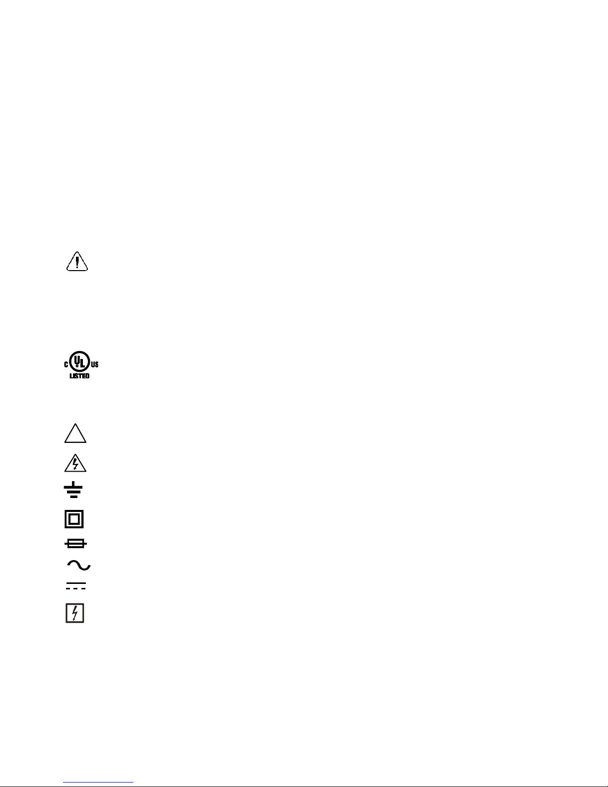
UL listing is not an indication or a verification of the accuracy of the meter
INTERNATIONAL ELECTRICAL SYMBOLS
!
Caution! Refer to the explanation in this Manual
Caution! Risk of electric shock
Earth (Ground)
Double Insulation or Reinforced insulation
Fuse
AC (Alternating Current)
DC (Direct Current)
Application around, and removal from, hazardous live conductors is permitted
CENELEC DIRECTIVES
The instruments conform to CENELEC Low-voltage directive 2014/35/EC, Electromagnetic
compatibility directive 2014/30/EU and RoHS directive 2011/65/EU.

FLIR CM4x USER MANUAL Document ID: CM4x-en-US_AA
7
3. Introduction
Thank you for selecting the FLIR Auto Range, True RMS 400A Clamp Meter with Low Pass
Filter and Accu-TipTM low current measurement technology.
All meters in this series measure 400A AC, 600V AC/DC, Resistance, Continuity,
Frequency, and Diode. Features include Non-Contact Voltage Detector, Data Hold,
MIN/MAX/AVG, and display backlighting.
The CM44 and CM46 also offer Capacitance, Peak, A DC (test leads), Relative/DC Zero,
and Thermocouple features.
The CM46 also provides DC, DC+ACV, and DC+DCA clamp measurements.
This device is shipped fully tested and calibrated and, with proper use, will provide years
of reliable service.
Key Features:
All Models
6000-count digital backlit display
600V AC/DC test lead measurements
Auto Range True RMS AC 400A AC clamp measurements
Low current Accu-Tip
TM
clamp measurements
AC bandwidth frequency 50~400Hz (50~60Hz for ACV and AC+DCV)
Frequency measurements 50~400Hz for ACA and 50~999.9Hz for ACV
Resistance measurements to 60k ohms
Continuity and Diode measurements
Non-contact (NCV) Voltage Detection (EF)
Display Hold
Minimum/Maximum/Average recording memory
Integrated VFD mode (Low-pass filter) on ACV and Hz measurements
Intelligent Auto power OFF (APO)
Jaw opening: 30mm (1.2”)
Safety Category Rating: CAT III 600V & CAT IV 300V AC & DC
CM44 and CM46 Features
Capacitance measurements
DC A test lead current measurements
Peak-rms inrush current detect to 80ms
Thermocouple temperature measurements
Relative/DC Zero functions
CM46-only Features
AC+DC measurements
40/400A DC Clamp measurements
FLIR CM4x USER MANUAL Document ID: CM4x-en-US_AA
8
4. Description
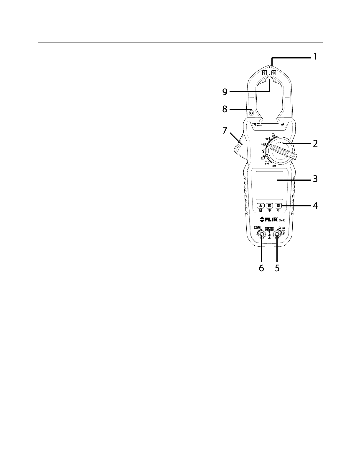
4.1 Meter Parts
1. Non-contact voltage detector
2. Function select switch
3. LCD Display
4. Control buttons
5. Positive (+) Probe Input jack
6. COM (negative -) Probe Input jack
7. Clamp jaw trigger
8. Clamp jaws
9. Low current Accu-Tip
TM
clamp area
Figure 4-1 Meter Description
Note: Battery compartment and Warning text label on back of meter.
FLIR CM4x USER MANUAL Document ID: CM4x-en-US_AA
9
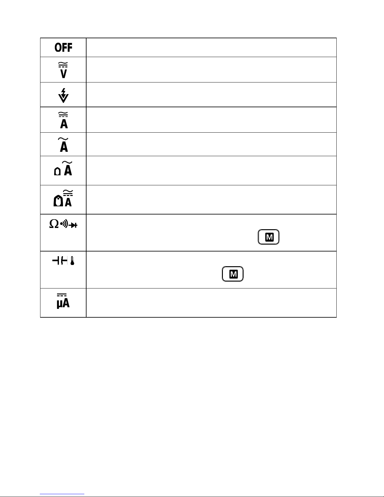
4.2 Function Switch Positions
Switch the meter OFF (full power saving mode)
Measure AC/DC Voltage through the probe inputs
Measure electric field (EF) using the non-contact voltage detector
Measure AC or DC current through the clamp jaws (CM46)
Measure AC current in the large clamp jaw area (CM42 and CM44)
Measure low AC current through the small clamp jaw area (AccuTipTM). CM42 and CM44
Measure low AC or DC current through the small clamp jaw area (AccuTipTM). CM46
Measure resistance, continuity, and diode through the probe inputs.
The type of measurement is chosen by the mode button.
Measure capacitance and temperature through the probe inputs. The
type of measurement is chosen by the button. CM44 and CM46
Measure DC microamperes (current) through the probe inputs. CM44
and CM46
FLIR CM4x USER MANUAL Document ID: CM4x-en-US_AA
10
4.3 Function Buttons
Short presses to access and step through MIN-MAX-AVG recorded
readings. Long press to exit the mode.
Long press to access 80ms PEAK RMS mode. CM44 and CM46.
Short presses to step through available modes for selected function
Long press to switch the display backlight ON or OFF. Backlight
switches off automatically after 32 seconds (approx.).
Short presses to access/exit the display hold mode
Relative Zero CM44
Relative & DC Zero CM46
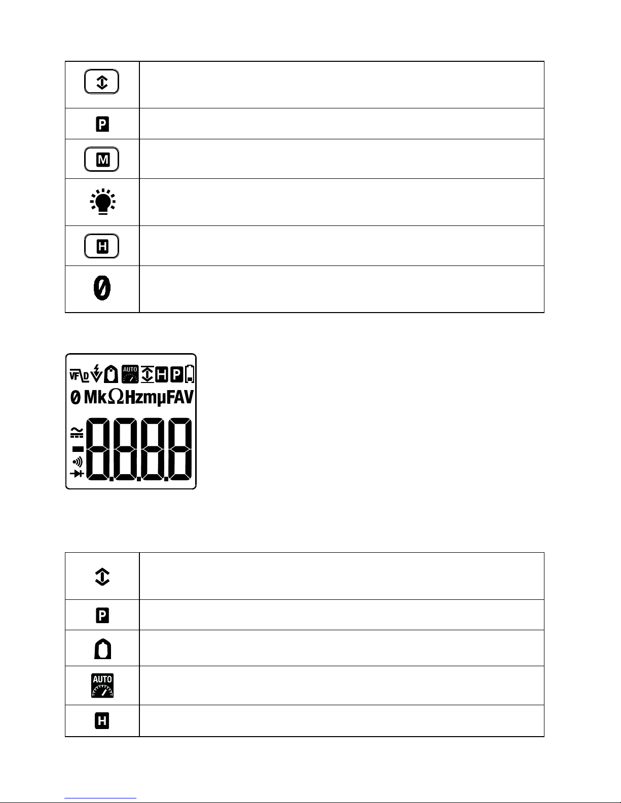
4.4 Display Icons and Indicators
Figure 4-2 Display Icon Descriptions
Refer to Fig. 4-2 above for the display icon descriptions below:
Meter is displaying maximum (up arrow), minimum (down arrow) or
average reading (up and down arrows)
80ms PEAK current/voltage rms mode
Low current Accu-TipTM mode
Auto range mode
Display Hold mode