

Page 1

User’s manual
FLIR B series
FLIR T series
1558792Publ. No.
a379Revision
English (EN)Language
August 14, 2009Issue date
Page 2

Page 3

User’s manual
Publ. No. 1558792 Rev. a379 – ENGLISH (EN) – August 14, 2009
Page 4

Legal disclaimer
All products manufactured by FLIR Systemsarewarranted against defectivematerialsandworkmanship for aperiodof one(1)year from the
delivery date of the original purchase, provided such products have been under normal storage, use and service, and in accordance with
FLIR Systems instruction.
All products not manufactured by FLIR Systems included in systemsdelivered by FLIRSystems to the original purchaser carrythe warranty,
if any, of the particular supplier only and FLIR Systems has no responsibilitywhatsoever for such products.
The warranty extends only to the original purchaser and is not transferable. It is not applicable to any product which has been subjected to
misuse, neglect, accident or abnormal conditions of operation. Expendable parts are excluded from the warranty.
In the case of adefect inaproduct coveredbythis warrantytheproduct must notbe furtherusedin order toprevent additional damage.The
purchaser shall promptly report any defect to FLIR Systems or this warranty will not apply.
FLIR Systems will, at its option, repair or replace any such defective product free of charge if, upon inspection, it proves to be defective in
material or workmanship and provided that it is returned to FLIR Systems within the said one-year period.
FLIR Systems has no other obligation or liability for defects than those set forth above.
No other warranty is expressed or implied. FLIR Systems specifically disclaims the implied warranties of merchantability and fitness for a
particular purpose.
FLIR Systems shall not be liable for any direct, indirect, special, incidentalor consequential loss or damage, whether basedon contract, tort
or any other legal theory.
Copyright
© FLIR Systems,2009. All rights reservedworldwide. No parts ofthesoftware including source codemaybe reproduced, transmitted, transcribed
or translated into any language or computer language in any form or by any means, electronic, magnetic, optical, manual or otherwise,
without the prior written permission of FLIR Systems.
This manual must not, in whole or part, be copied, photocopied, reproduced,translated ortransmitted to any electronic medium or machine
readable form without prior consent, in writing, from FLIR Systems.
Names and marks appearing on the products herein are eitherregistered trademarksor trademarksof FLIR Systems and/or its subsidiaries.
All othertrademarks,trade names or companynames referenced herein areusedfor identification only andarethe property of theirrespective
owners.
Quality assurance
The Quality Management System under which these products are developed and manufactured has been certified in accordance with the
ISO 9001 standard.
FLIR Systems is committed to a policy of continuous development; therefore we reserve the right to make changes and improvements on
any of the products described in this manual without prior notice.
Patents
One or several of the following patents or design patents apply to the products and/or features described in this manual:
0002258-2; 000279476-0001;000439161;000499579-0001; 000653423; 000726344; 000859020;0101577-5; 0102150-0; 0200629-4; 0300911-
5; 0302837-0; 1144833;1182246;1182620; 1188086; 1263438; 1285345; 1287138; 1299699;1325808;1336775;1678485;200530018812.0;
2106017; 235308; 3006596; 3006597; 466540; 483782; 484155; 518836; 60004227.8; 60122153.2; 602004011681.5-08; 6707044; 68657;
7034300; 7110035; 7154093; 7157705; 7237946; 7312822; 7332716; 7336823; 75530; D540838; D549758; DI6702302-9; DI6703574-4;
DM/057692; DM/061609;ZL00809178.1;ZL01823221.3; ZL01823226.4; ZL02331553.9; ZL02331554.7;ZL200530120994.2; ZL200630130114.4;
ZL200730151141.4.
EULA Terms
You have acquired a device (“INFRARED CAMERA”) that includes software licensed by FLIR Systems AB from Microsoft Licensing, GP
■
or its affiliates (“MS”). Those installed software products of MS origin, as well as associated media, printed materials, and “online” or
electronic documentation(“SOFTWARE”)are protected by internationalintellectualproperty laws and treaties.TheSOFTWARE is licensed,
not sold. All rights reserved.
IF YOU DO NOTAGREE TO THISENDUSER LICENSE AGREEMENT(“EULA”), DO NOTUSETHE DEVICE ORCOPYTHESOFTWARE.
■
INSTEAD, PROMPTLY CONTACT FLIR Systems AB FOR INSTRUCTIONS ON RETURN OF THE UNUSED DEVICE(S) FOR A REFUND.
ANY USE OF THE SOFTWARE, INCLUDING BUT NOT LIMITED TO USE ON THE DEVICE, WILL CONSTITUTE YOUR AGREEMENT
TO THIS EULA (OR RATIFICATION OF ANY PREVIOUS CONSENT).
GRANT OF SOFTWARE LICENSE. This EULA grants you the following license:
■
You may use the SOFTWARE only on the DEVICE.
■
NOT FAULT TOLERANT. THE SOFTWARE IS NOT FAULT TOLERANT. FLIR Systems AB HAS INDEPENDENTLY DETERMINED
■
HOW TOUSE THE SOFTWAREIN THE DEVICE,AND MS HASRELIED UPON FLIRSystems AB TOCONDUCT SUFFICIENT TESTING
TO DETERMINE THAT THE SOFTWARE IS SUITABLE FOR SUCH USE.
iv Publ. No. 1558792 Rev. a379 – ENGLISH (EN) – August 14, 2009
Page 5

NO WARRANTIES FOR THE SOFTWARE. THE SOFTWARE is provided “AS IS” and with all faults. THE ENTIRE RISK AS TO SAT-
■
ISFACTORY QUALITY, PERFORMANCE, ACCURACY, AND EFFORT (INCLUDING LACK OF NEGLIGENCE) IS WITH YOU. ALSO,
THERE ISNO WARRANTY AGAINSTINTERFERENCE WITH YOURENJOYMENT OF THESOFTWAREOR AGAINST INFRINGEMENT.
IF YOU HAVE RECEIVED ANY WARRANTIES REGARDING THE DEVICE OR THE SOFTWARE, THOSE WARRANTIES DO NOT
ORIGINATE FROM, AND ARE NOT BINDING ON, MS.
No Liability for Certain Damages. EXCEPT AS PROHIBITED BY LAW, MS SHALL HAVE NO LIABILITY FOR ANY INDIRECT,
■
SPECIAL, CONSEQUENTIAL OR INCIDENTAL DAMAGES ARISING FROM OR IN CONNECTION WITH THE USE OR PERFORMANCE OF THE SOFTWARE. THIS LIMITATION SHALL APPLY EVEN IF ANY REMEDY FAILS OF ITS ESSENTIAL PURPOSE.
IN NO EVENT SHALL MS BE LIABLE FOR ANY AMOUNT IN EXCESS OF U.S. TWO HUNDRED FIFTY DOLLARS (U.S.$250.00).
Limitations on Reverse Engineering, Decompilation, and Disassembly. Youmay not reverse engineer, decompile, ordisassemble
■
the SOFTWARE, exceptand only to the extentthat such activity isexpresslypermitted by applicable lawnotwithstandingthis limitation.
SOFTWARE TRANSFER ALLOWED BUT WITH RESTRICTIONS. Youmaypermanentlytransferrights under this EULA only aspart
■
of a permanent sale or transfer of the Device, and only if the recipient agrees to this EULA. If the SOFTWARE is an upgrade, any
transfer must also include all prior versions of the SOFTWARE.
EXPORT RESTRICTIONS. You acknowledge that SOFTWARE is subject to U.S. export jurisdiction. You agree to comply with all
■
applicable international andnationallawsthatapplytotheSOFTWARE, includingthe U.S. Export Administration Regulations,aswell
as end-user, end-use and destination restrictions issued by U.S. and other governments. For additional information see
http://www.microsoft.com/exporting/.
Publ. No. 1558792 Rev. a379 – ENGLISH (EN) – August 14, 2009
Page 6

vi Publ. No. 1558792 Rev. a379 – ENGLISH (EN) – August 14, 2009
Page 7

Table of contents
11 Warnings & Cautions .....................................................................................................................
32 Notice to user ..................................................................................................................................
43 Customer help ................................................................................................................................
54 Documentation updates .................................................................................................................
65 Important note about this manual .................................................................................................
76 Quick Start Guide ...........................................................................................................................
87 List of accessories .........................................................................................................................
98 A note about ergonomics ..............................................................................................................
109 Camera parts ...................................................................................................................................
109.1 View of the rear .....................................................................................................................
139.2 View of the front ....................................................................................................................
159.3 View of the bottom side ........................................................................................................
169.4 Battery condition indicator ...................................................................................................
179.5 Laser pointer .........................................................................................................................
1910 Toolbars and work areas ................................................................................................................
1910.1 Work areas ............................................................................................................................
1910.1.1 Operation mode area ............................................................................................
2110.1.2 Main work area .....................................................................................................
2210.1.3 Sketch work area ..................................................................................................
2410.1.4 Text annotation and image description work area ...............................................
2710.2 Toolbars ................................................................................................................................
2710.2.1 Measurement toolbar ............................................................................................
2910.2.2 Documentation toolbar .........................................................................................
3110.2.3 Image marker toolbar ...........................................................................................
3210.2.4 Voice annotation toolbar .......................................................................................
3310.2.5 Video recording toolbar ........................................................................................
3410.2.6 Periodic save toolbar ............................................................................................
3510.2.7 Work folder toolbar ...............................................................................................
3611 Navigating the menu system .........................................................................................................
3712 External devices and storage media ............................................................................................
3812.1 Connecting external devices ................................................................................................
3912.2 Inserting SD Memory Cards .................................................................................................
4013 Handling the camera ......................................................................................................................
13.1.1 Using the combined power supply and battery charger to charge the battery
when it is inside the camera .................................................................................
13.1.2 Using the combined power supply and battery charger to charge the battery
when it is outside the camera ...............................................................................
Publ. No. 1558792 Rev. a379 – ENGLISH (EN) – August 14, 2009 vii
4013.1 Charging the battery .............................................................................................................
41
42
4313.1.3 Using the stand-alone battery charger to charge the battery ..............................
4413.2 Inserting the battery ..............................................................................................................
Page 8

4613.3 Removing the battery ...........................................................................................................
4813.4 Turning on the camera .........................................................................................................
4813.5 Turning off the camera ..........................................................................................................
4813.6 Entering standby mode ........................................................................................................
4813.7 Exiting standby mode ...........................................................................................................
4913.8 Adjusting the angle of lens ...................................................................................................
5013.9 Mounting an additional infrared lens ....................................................................................
5213.10 Removing an additional infrared lens ..................................................................................
5413.11 Attaching the sunshield ........................................................................................................
5613.12 Using the laser pointer .........................................................................................................
5714 Working with images and folders .................................................................................................
5714.1 Adjusting the infrared camera focus ....................................................................................
5814.2 Previewing an image ............................................................................................................
5914.3 Saving an image ...................................................................................................................
6014.4 Periodically saving an image ................................................................................................
6114.5 Opening an image ................................................................................................................
6214.6 Using the Panorama function ...............................................................................................
6414.7 Adjusting an image manually ...............................................................................................
6714.8 Hiding overlay graphics ........................................................................................................
6814.9 Deleting an image .................................................................................................................
6914.10 Deleting all images ...............................................................................................................
7014.11 Working with folders .............................................................................................................
7315 Working with fusion ........................................................................................................................
7816 Recording video clips ....................................................................................................................
7917 Working with measurement tools and isotherms .......................................................................
7917.1 Setting up measurement tools .............................................................................................
8017.2 Setting up measurement tools (advanced mode) ...............................................................
8117.3 Setting up a difference calculation .......................................................................................
8217.4 Setting up isotherms ............................................................................................................
8417.5 Screening of elevated facial temperatures ...........................................................................
8617.6 Removing measurement tools .............................................................................................
8717.7 Moving measurement tools ..................................................................................................
8817.8 Resizing areas ......................................................................................................................
8917.9 Changing object parameters ................................................................................................
9118 Annotating images ..........................................................................................................................
9218.1 Adding a digital photo ..........................................................................................................
9318.2 Adding a voice annotation ....................................................................................................
9418.3 Adding a text annotation ......................................................................................................
9718.4 Adding an image description ...............................................................................................
9818.5 Adding a sketch ....................................................................................................................
9918.6 Adding an image marker ......................................................................................................
10019 Changing settings ..........................................................................................................................
10019.1 Changing image settings .....................................................................................................
10119.2 Changing regional settings ..................................................................................................
10219.3 Changing camera settings ...................................................................................................
10320 Cleaning the camera ......................................................................................................................
10320.1 Camera housing, cables, and other items ...........................................................................
viii Publ. No. 1558792 Rev. a379 – ENGLISH (EN) – August 14, 2009
Page 9

24.2.1.2 Guidelines for moisture detection, mold detection & detection of
water damages ..................................................................................
10420.2 Infrared lens ..........................................................................................................................
10521 Technical data .................................................................................................................................
10521.1 T series cameras ..................................................................................................................
12321.2 B series cameras ..................................................................................................................
14022 Dimensions ......................................................................................................................................
14022.1 Camera .................................................................................................................................
14022.1.1 Camera dimensions ..............................................................................................
14122.1.2 Camera dimensions, continued ...........................................................................
14222.1.3 Camera dimensions, continued ...........................................................................
14322.1.4 Camera dimensions, continued (with 30 mm/15° lens) .......................................
14422.1.5 Camera dimensions, continued (with 10 mm/45° lens) .......................................
14522.2 Battery ...................................................................................................................................
14622.3 Stand-alone battery charger .................................................................................................
14722.4 Stand-alone battery charger with the battery .......................................................................
14822.5 Infrared lens (30 mm/15°) .....................................................................................................
14922.6 Infrared lens (10 mm/45°) .....................................................................................................
15023 Application examples .....................................................................................................................
15023.1 Moisture & water damage ....................................................................................................
15123.2 Faulty contact in socket ........................................................................................................
15223.3 Oxidized socket ....................................................................................................................
15323.4 Insulation deficiencies ..........................................................................................................
15423.5 Draft ......................................................................................................................................
15524 Introduction to building thermography ........................................................................................
15524.1 Important note ......................................................................................................................
15524.2 Typical field investigations ....................................................................................................
15524.2.1 Guidelines .............................................................................................................
15524.2.1.1 General guidelines ............................................................................
156
15624.2.1.3 Guidelines for detection of air infiltration & insulation deficiencies ...
15724.2.2 About moisture detection .....................................................................................
15724.2.3 Moisture detection (1): Low-slope commercial roofs ..........................................
15724.2.3.1 General information ...........................................................................
15824.2.3.2 Safety precautions ............................................................................
15924.2.3.3 Commented building structures .......................................................
16024.2.3.4 Commented infrared images ............................................................
16224.2.4 Moisture detection (2): Commercial & residential façades ..................................
16224.2.4.1 General information ...........................................................................
16224.2.4.2 Commented building structures .......................................................
16424.2.4.3 Commented infrared images ............................................................
16424.2.5 Moisture detection (3): Decks & balconies ..........................................................
16424.2.5.1 General information ...........................................................................
16524.2.5.2 Commented building structures .......................................................
16724.2.5.3 Commented infrared images ............................................................
16724.2.6 Moisture detection (4): Plumbing breaks & leaks ................................................
16724.2.6.1 General information ...........................................................................
16824.2.6.2 Commented infrared images ............................................................
17024.2.7 Air infiltration .........................................................................................................
17024.2.7.1 General information ...........................................................................
17024.2.7.2 Commented building structures .......................................................
Publ. No. 1558792 Rev. a379 – ENGLISH (EN) – August 14, 2009 ix
Page 10

24.3.8 Excerpt from Technical Note ‘Assessing thermal bridging and insulation
continuity’ (UK example) ......................................................................................
17224.2.7.3 Commented infrared images ............................................................
17324.2.8 Insulation deficiencies ..........................................................................................
17324.2.8.1 General information ...........................................................................
17324.2.8.2 Commented building structures .......................................................
17524.2.8.3 Commented infrared images ............................................................
17724.3 Theory of building science ...................................................................................................
17724.3.1 General information ..............................................................................................
17824.3.2 The effects of testing and checking .....................................................................
17924.3.3 Sources of disruption in thermography ................................................................
18124.3.4 Surface temperature and air leaks .......................................................................
18124.3.4.1 Pressure conditions in a building .....................................................
18724.3.5 Measuring conditions & measuring season .........................................................
18724.3.6 Interpretation of infrared images ..........................................................................
18924.3.7 Humidity & dew point ...........................................................................................
18924.3.7.1 Relative & absolute humidity ............................................................
19024.3.7.2 Definition of dew point ......................................................................
190
19024.3.8.1 Credits ...............................................................................................
19124.3.8.2 Introduction .......................................................................................
19124.3.8.3 Background information ...................................................................
19224.3.8.4 Quantitative appraisal of thermal anomalies ....................................
19524.3.8.5 Conditions and equipment ...............................................................
19624.3.8.6 Survey and analysis ..........................................................................
19724.3.8.7 Reporting ...........................................................................................
19924.4 Disclaimer .............................................................................................................................
19924.4.1 Copyright notice ...................................................................................................
19924.4.2 Training & certification ..........................................................................................
19924.4.3 National or regional building codes .....................................................................
20025 Introduction to thermographic inspections of electrical installations ......................................
20025.1 Important note ......................................................................................................................
20025.2 General information ..............................................................................................................
20025.2.1 Introduction ...........................................................................................................
20125.2.2 General equipment data .......................................................................................
20225.2.3 Inspection .............................................................................................................
20225.2.4 Classification & reporting ......................................................................................
20325.2.5 Priority ...................................................................................................................
20325.2.6 Repair ....................................................................................................................
20425.2.7 Control ..................................................................................................................
20525.3 Measurement technique for thermographic inspection of electrical installations ...............
20525.3.1 How to correctly set the equipment .....................................................................
20525.3.2 Temperature measurement ...................................................................................
20725.3.3 Comparative measurement ..................................................................................
20825.3.4 Normal operating temperature .............................................................................
20925.3.5 Classification of faults ...........................................................................................
21125.4 Reporting ..............................................................................................................................
21325.5 Different types of hot spots in electrical installations ...........................................................
21325.5.1 Reflections ............................................................................................................
21325.5.2 Solar heating .........................................................................................................
21425.5.3 Inductive heating ...................................................................................................
21425.5.4 Load variations ......................................................................................................
21525.5.5 Varying cooling conditions ...................................................................................
x Publ. No. 1558792 Rev. a379 – ENGLISH (EN) – August 14, 2009
Page 11

21625.5.6 Resistance variations ............................................................................................
21625.5.7 Overheating in one part as a result of a fault in another ......................................
21825.6 Disturbance factors at thermographic inspection of electrical installations ........................
21825.6.1 Wind ......................................................................................................................
21825.6.2 Rain and snow ......................................................................................................
21925.6.3 Distance to object .................................................................................................
22025.6.4 Object size ............................................................................................................
22225.7 Practical advice for the thermographer ................................................................................
22225.7.1 From cold to hot ...................................................................................................
22225.7.2 Rain showers ........................................................................................................
22225.7.3 Emissivity ..............................................................................................................
22325.7.4 Reflected apparent temperature ...........................................................................
22325.7.5 Object too far away ...............................................................................................
22426 About FLIR Systems .......................................................................................................................
22526.1 More than just an infrared camera .......................................................................................
22526.2 Sharing our knowledge ........................................................................................................
22526.3 Supporting our customers ...................................................................................................
22626.4 A few images from our facilities ...........................................................................................
22827 Glossary ...........................................................................................................................................
23228 Thermographic measurement techniques ...................................................................................
23228.1 Introduction ..........................................................................................................................
23228.2 Emissivity ..............................................................................................................................
23328.2.1 Finding the emissivity of a sample .......................................................................
23328.2.1.1 Step 1: Determining reflected apparent temperature .......................
23528.2.1.2 Step 2: Determining the emissivity ...................................................
23628.3 Reflected apparent temperature ..........................................................................................
23628.4 Distance ................................................................................................................................
23628.5 Relative humidity ..................................................................................................................
23628.6 Other parameters ..................................................................................................................
23729 History of infrared technology ......................................................................................................
24130 Theory of thermography ................................................................................................................
24130.1 Introduction ...........................................................................................................................
24130.2 The electromagnetic spectrum ............................................................................................
24230.3 Blackbody radiation ..............................................................................................................
24330.3.1 Planck’s law ..........................................................................................................
24430.3.2 Wien’s displacement law ......................................................................................
24630.3.3 Stefan-Boltzmann's law .........................................................................................
24730.3.4 Non-blackbody emitters .......................................................................................
24930.4 Infrared semi-transparent materials .....................................................................................
25131 The measurement formula .............................................................................................................
25732 Emissivity tables .............................................................................................................................
25732.1 References ............................................................................................................................
25732.2 Important note about the emissivity tables ..........................................................................
25832.3 Tables ....................................................................................................................................
Publ. No. 1558792 Rev. a379 – ENGLISH (EN) – August 14, 2009 xi
Page 12

xii Publ. No. 1558792 Rev. a379 – ENGLISH (EN) – August 14, 2009
Page 13

1 Warnings & Cautions
This equipment generates, uses, and can radiate radio frequency energy and if
WARNING
■
not installed and used in accordance with the instruction manual, may cause interference to radio communications. It has been tested and found to comply with
the limits for a Class A computing device pursuant to Subpart J of Part 15 of FCC
Rules, which are designedto providereasonable protection againstsuch interference when operated in a commercial environment. Operation of this equipment
in a residential area is likely to cause interference in which case the user at his
own expense will be required to take whatever measures may be required to
correct the interference.
(Applies only to cameras with laser pointer:) Do not look directly into the laser
■
beam. The laser beam can cause eye irritation.
Applies only to cameras with battery:
■
Do not disassemble or do a modification to the battery. The battery contains
■
safety and protection devices which, if they become damaged, can cause the
battery to become hot, or cause an explosion or an ignition.
If there is a leak from the battery and the fluid gets into your eyes, do not rub
■
your eyes.Flush well withwater and immediatelyget medical care. Thebattery
fluid can cause injury to your eyes if you do not do this.
Do not continue to charge the battery if it does not become charged in the
■
specified charging time. If you continue to charge the battery, it can become
hot and cause an explosion or ignition.
Only use the correct equipment to discharge the battery. If you do not use the
■
correct equipment, you can decrease the performance or the life cycle of the
battery. If you do not use the correct equipment, an incorrect flow of current
to the battery can occur. This can cause the battery to become hot, or cause
an explosion and injury to persons.
Make sure that you read all applicable MSDS (Material Safety Data Sheets) and
■
warning labelson containersbeforeyou usea liquid: theliquids can bedangerous.
Do not point theinfrared camera (withor without the lens cover)at intensive energy
CAUTION
■
sources, for example devices that emit laser radiation, or the sun. This can have
an unwanted effect on the accuracy of the camera. It can also cause damage to
the detector in the camera.
Do not use the camera in a temperature higher than +50°C (+122°F), unless
■
specified otherwise in the user documentation. High temperatures can cause
damage to the camera.
(Applies only to cameras with laser pointer:) Protect the laser pointer with the
■
protective cap when you do not operate the laser pointer.
Applies only to cameras with battery:
■
Do not attach the batteries directly to a car’s cigarette lighter socket, unless a
■
specific adapter for connecting the batteries to a cigarette lighter socket is
provided by FLIR Systems.
Do not connect the positive terminal and the negative terminal of the battery
■
to each other with a metal object (such as wire).
Do not get water or salt water on the battery, or permit the battery to get wet.
■
Publ. No. 1558792 Rev. a379 – ENGLISH (EN) – August 14, 2009 1
Page 14

1 – Warnings & Cautions
■
■
■
Do not make holes in the battery with objects. Do not hit the battery with a
■
hammer. Do not step on the battery, or apply strong impacts or shocks to it.
Do not put thebatteries inor near a fire, orinto direct sunlight. When thebattery
■
becomes hot, the built-in safety equipment becomes energized and can stop
the battery charging process. If the battery becomes hot, damage can occur
to the safety equipment and this can cause more heat, damage or ignition of
the battery.
Do not put the battery on a fire or increase the temperature of the battery with
■
heat.
Do not put the battery on or near fires, stoves, or other high-temperature loca-
■
tions.
Do not solder directly onto the battery.
■
Do not use the battery if, when you use, charge, or store the battery, there is
■
an unusual smell fromthe battery,the battery feelshot, changes color, changes
shape, or is in an unusual condition. Contact your sales office if one or more
of these problems occurs.
Only use a specified battery charger when you charge the battery.
■
The temperature range through which you can charge the battery is ±0°C to
■
+45°C (+32°F to +113°F), unless specified otherwise in the user documentation. If you charge the battery at temperatures out of this range, it can cause
the battery to become hot or to break. It can also decrease the performance
or the life cycle of the battery.
The temperature range through which you can dischargethe battery is −15°C
■
to +50°C (+5°F to +122°F), unless specified otherwise in the user documentation. Use of the battery out of this temperature range can decrease the performance or the life cycle of the battery.
When the battery is worn, apply insulation to the terminals with adhesive tape
■
or similar materials before you discard it.
Do not apply solvents or similar liquids to the camera, the cables, or other items.
This can cause damage.
Be careful when you cleanthe infraredlens. The lens has a delicate anti-reflective
coating.
Do not clean the infrared lens too vigorously. This can damage the anti-reflective
coating.
2 Publ. No. 1558792 Rev. a379 – ENGLISH (EN) – August 14, 2009
Page 15
2 Notice to user
Typographical
conventions
User-to-user
forums
Calibration
Accuracy
Disposal of
electronic waste
This manual uses the following typographical conventions:
Semibold is used for menu names, menu commands and labels, and buttons in
■
dialog boxes.
Italic is used for important information.
■
Monospace is used for code samples.
■
UPPER CASE is used for names on keys and buttons.
■
Exchange ideas,problems, and infraredsolutions with fellowthermographers around
the world in our user-to-user forums. To go to the forums, visit:
http://www.infraredtraining.com/community/boards/
(This notice only applies to cameras with measurement capabilities.)
We recommend that you send in the camera for calibration once a year. Contact
your local sales office for instructions on where to send the camera.
(This notice only applies to cameras with measurement capabilities.)
For very accurate results, we recommend that you wait 5 minutes after you have
started the camera before measuring a temperature.
For cameras where the detector is cooled by a mechanical cooler, this time period
excludes the time it takes to cool down the detector (usually 5–7 minutes).
10742803;a1
As with most electronic products, this equipment must be disposed of in an environmentally friendlyway, and inaccordance with existingregulations for electronicwaste.
Please contact your FLIR Systems representative for more details.
Publ. No. 1558792 Rev. a379 – ENGLISH (EN) – August 14, 2009 3
Page 16

3 Customer help
General
Submitting a
question
Downloads
For customer help, visit:
http://flir.custhelp.com
To submit a question to the customer help team, you must be a registered user. It
only takes a fewminutes to registeronline. If you only wantto search the knowledgebase for existing questions and answers, you do not need to be a registered user.
When you want to submit a question, makesure thatyou have the following information to hand:
The camera model
■
The camera serial number
■
The communication protocol, or method, between the camera and your PC (for
■
example, HDMI, Ethernet, USB™, or FireWire™)
Operating system on your PC
■
Microsoft®Office version
■
Full name, publication number, and revision number of the manual
■
On the customer help site you can also download the following:
Firmware updates for your infrared camera
■
Program updates for your PC software
■
User documentation
■
Application stories
■
Technical publications
■
4 Publ. No. 1558792 Rev. a379 – ENGLISH (EN) – August 14, 2009
Page 17

4 Documentation updates
General
Our manuals are updated several times per year, and we also issue product-critical
notifications of changes on a regular basis.
To access the latest manuals and notifications, go to the Download tab at:
http://flir.custhelp.com
It only takes a few minutes to register online. In the download area you will also find
the latest releases of manuals for our other products, as well as manuals for our
historical and obsolete products.
Publ. No. 1558792 Rev. a379 – ENGLISH (EN) – August 14, 2009 5
Page 18

5 Important note about this manual
General
NOTE
FLIR Systems issues generic manuals that cover several cameras within a model
line.
This means that this manual may contain descriptions and explanations that do not
apply to your particular camera model.
FLIR Systemsreserves therightto discontinuemodels,software, parts oraccessories,
and other items, or to change specifications and/or functionality at any time without
prior notice.
6 Publ. No. 1558792 Rev. a379 – ENGLISH (EN) – August 14, 2009
Page 19

6 Quick Start Guide
Procedure
SEE
Follow this procedure to get started right away:
Charge the battery for four hours.1
Insert the battery into the camera.2
Insert an SD Memory Card into the card slot at the top of the camera.3
Push the On/Off button to turn on the camera.4
Set the correct object temperature range.5
Aim the camera toward your target of interest.6
Use the Focus button to focus the camera.7
Push the Preview/Save button to save the image.8
To move the image to a computer, do one of the following:
9
Remove the SD Memory Card and insert it into a card reader connected
■
to a computer.
Connect a computer to the camera using a USB Mini-B cable.
■
Move the image from the card or camera using a drag-and-drop operation.10
Section 13.1 – Charging the battery on page 40
■
Section 13.2 – Inserting the battery on page 44
■
Section 12.2 – Inserting SD Memory Cards on page 39
■
Section 13.4 – Turning on the camera on page 48
■
Section 19.1 – Changing image settings on page 100
■
Section 17 – Working with measurement tools and isotherms on page 79
■
Section 12.1 – Connecting external devices on page 38
■
Publ. No. 1558792 Rev. a379 – ENGLISH (EN) – August 14, 2009 7
Page 20

7 List of accessories
General
Contents
This section contains a list of accessories that you can purchase for your camera.
The accessories included in the transport case depends on the camera model and
customer configuration.
12 VDC power cable with cigarette lighter adapter
Additional infrared lens (10 mm/45°)
Additional infrared lens (30 mm/15°)
Battery
Battery charger
Camera pouch
Documentation CD-ROM (including reference manuals in multiple languages,
application guides, etc.)
Lens cap for infrared camera
Microphone headset
Neck strap
Power cord
Power supply
Printed Getting Started Guide
SD memory card, 256 MB
Stylus pen
Sunshield
USB cable
Video cable
NOTE
FLIR Systems reserves the right to discontinue models, parts or accessories, and
other items, or to change specifications at any time without prior notice.
8 Publ. No. 1558792 Rev. a379 – ENGLISH (EN) – August 14, 2009
Page 21
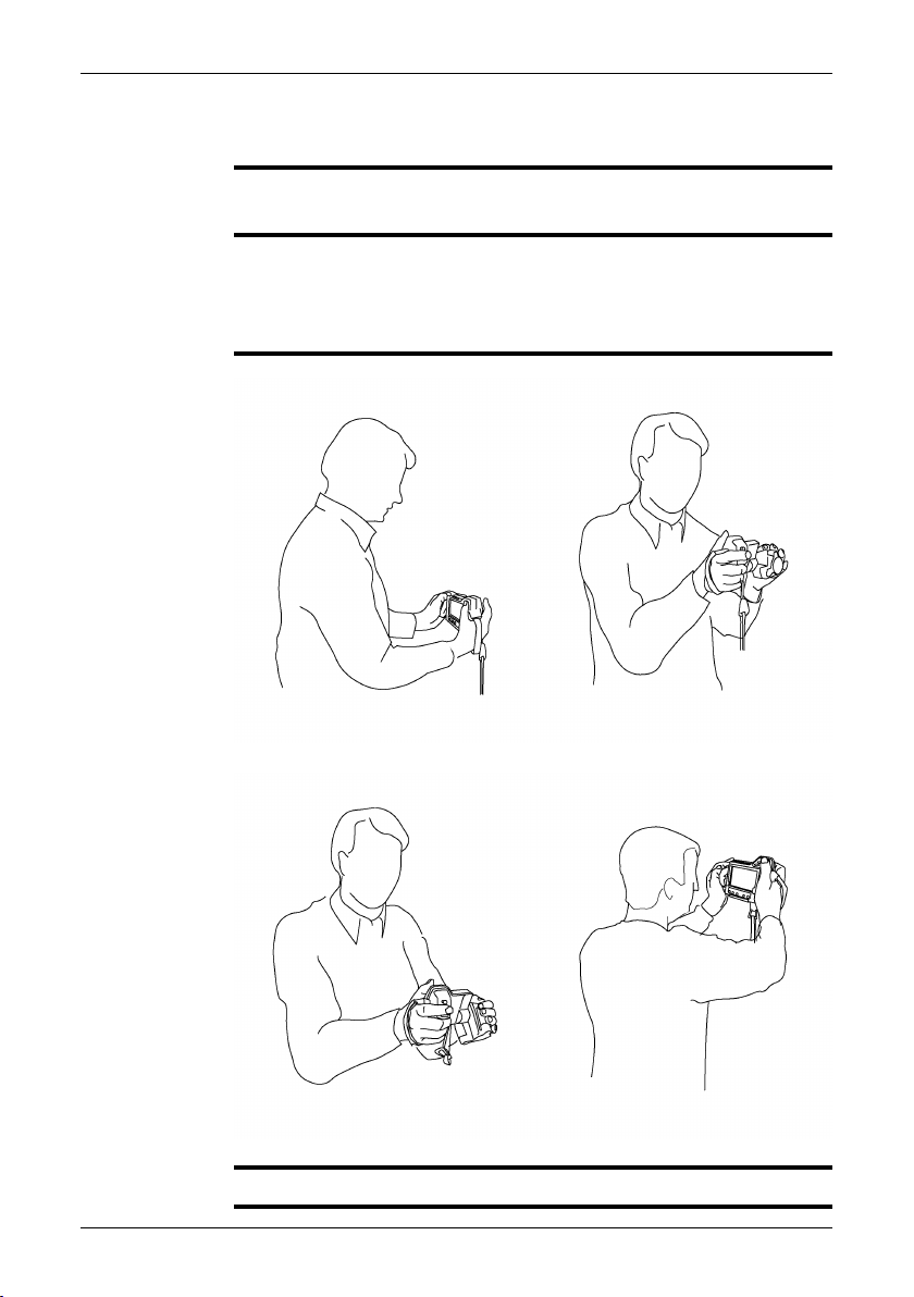
8 A note about ergonomics
General
NOTE
Figure
To prevent strain injuries, it is important that you hold the camera ergonomically
correct. This section gives advice and examples on how to hold the camera.
Please note the following:
Always adjust the angle of the lens to suit your work position.
■
When you hold the camera, make sure that you support the camera housing with
■
your left hand too. This decreases the strain on your right hand.
10758503;a1 10758603;a1
10758703;a110758803;a1
Section 13.8 – Adjusting the angle of lens on page 49
SEE ALSO
Publ. No. 1558792 Rev. a379 – ENGLISH (EN) – August 14, 2009 9
■
Page 22
9 Camera parts
9.1 View of the rear
Figure
Explanation
10758903;a1
This table explains the figure above:
Touch screen LCD1
Cover for SD Memory Card slot2
10 Publ. No. 1558792 Rev. a379 – ENGLISH (EN) – August 14, 2009
Page 23

Zoom button
3
The zoom button has the following functions on live images:
■
Push to enter the zoom state.
■
Use the joystick to zoom into or out of an image.
■
Push the zoom button once again to reset to 1× zoom factor.
■
Push the A/M button, the joystick, or the Preview/Save button to
■
confirm the zoom factor and leave the zoom state.
The zoom button has the following functions on still images:
■
Zooming:
■
Push to enter the zoom state.
■
Use the joystick to zoom into or out of an image.
■
Push the zoom button once again to reset to 1× zoom factor.
■
Push the A/M button or the Preview/Save button to confirm the
■
zoom factor and leave the zoom state.
Panning:
■
Push to enter the zoom state.
■
Push the joystick to enter the pan state.
■
Use the joystick to pan over an image.
■
Push the joystick to confirm the pan position and leave the pan
■
state.
Stylus pen
4
Note: Push the stylus pen firmly into its holder when not in use.
9 – Camera parts
Camera button
5
The camera button has the following functions:
On live images: Switch between the infrared camera and the digital
■
camera (IR > DC).
On live fusion images: Switch between fusion and infrared imagery.
■
Switching betweenfusion and infraredimagery enables youto accurately
focus the infrared image (IR > DC > fusion).
You can set up the behavior of this button under Setup.
Joystick
6
The joystick has the following functions:
In live infrared manual mode, and in still infrared mode:
■
Push up/down to adjust the level.
■
Push left/right to adjust the span.
■
In menus, in dialog boxes, and in the image archive:
■
Push up/down or left/right to navigate.
■
Push to confirm choices.
■
Publ. No. 1558792 Rev. a379 – ENGLISH (EN) – August 14, 2009 11
Page 24

9 – Camera parts
A/M button
7
The A/M button has the following functions:
Push to switch between automatic and manual adjustment modes.
■
Push and hold down for more than one second to perform a non-unifor-
■
mity correction.
In still infrared mode: Switch user focus between the documentation
■
toolbar and the temperature scale.
In still infrared mode and in recall mode: Push and hold down for more
■
than one second to perform a one-shot auto-adjust.
Measure button
8
The Measure button has the following functions:
In live infrared mode: Push to display/hide the measurement menu.
■
In still infrared mode: Push to display/hide the measurement toolbar.
■
Info button
9
The function of the Info button is to display different levels of information
on the screen.
Setup button
10
The function of the Setup button is to display/hide the setup menu. In the
setup modeyou can change image settings,camera settings, andregional
settings.
Archive button
11
The Archive button has the following functions:
Push to open the image archive.
■
Push to close the image archive.
■
Mode button
12
The function of the mode button is to display/hide the mode selector.
On/Off button.
13
The On/Off button has the following functions:
To turn on the camera, push the On/Off button.
■
To turn off the camera, push and hold down the On/Off button for more
■
than 2 seconds.
To enter the standby mode, push and hold down the On/Off button for
■
approx. 0.2 seconds.
To exit the standby mode, push and hold down the On/Off button for
■
approx. 0.2 seconds.
The On/Off button is also a power indicator that shows when the camera
is on.
Hand strap14
12 Publ. No. 1558792 Rev. a379 – ENGLISH (EN) – August 14, 2009
Page 25
9.2 View of the front
9 – Camera parts
Figure
Explanation
10759003;a1
This table explains the figure above:
Laser pointer button
1
The laser pointer button has the following functions:
Push the laser pointer button to turn on the laser pointer.
■
Release the laser pointer button to turn off the laser pointer.
■
Save/Preview button
2
The Save/Preview button has the following functions:
Push andhold down theSave/Preview button formore than one second
■
to preview an image. At this point you can annotate the image with a
digital photo, a text annotation, a voice annotation, image markers, etc.
Briefly push the Save/Preview button to save an infrared image in the
■
infrared camera mode (without previewing).
Briefly pushthe Save/Preview buttonto save a digital photoin the digital
■
camera mode (without previewing).
Focus button
3
The focus button has the following functions:
Move the Focus button left for far focus.
■
Move the Focus button right for close focus.
■
Briefly push the Focus button to autofocus.
■
Note: It is important that you hold the camera steady while autofocusing.
Publ. No. 1558792 Rev. a379 – ENGLISH (EN) – August 14, 2009 13
Page 26

9 – Camera parts
Protective edge for the focus button4
Attachment point for the neck strap5
Video lamp6
Digital camera lens7
Release button for additional infrared lenses8
Laser pointer9
Infrared lens10
Lens cap for the infrared lens11
NOTE
The laser pointer may not be enabled in all markets.
14 Publ. No. 1558792 Rev. a379 – ENGLISH (EN) – August 14, 2009
Page 27
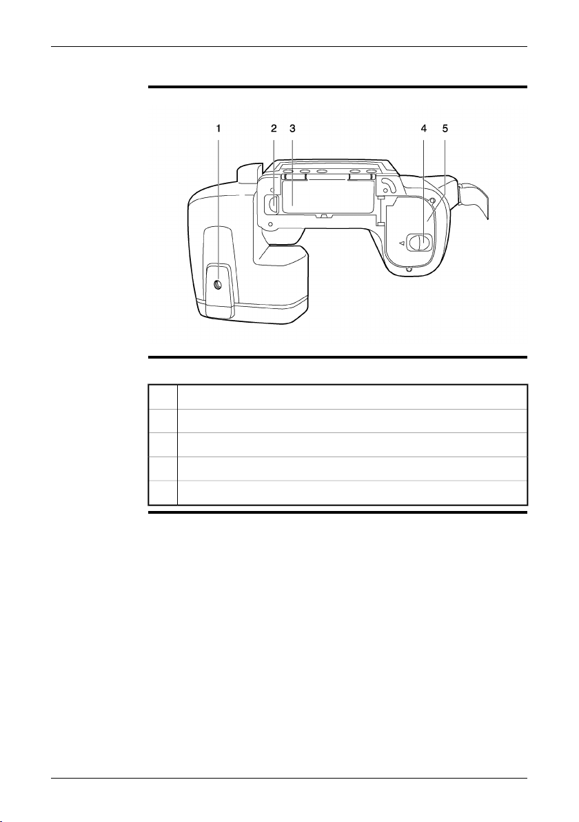
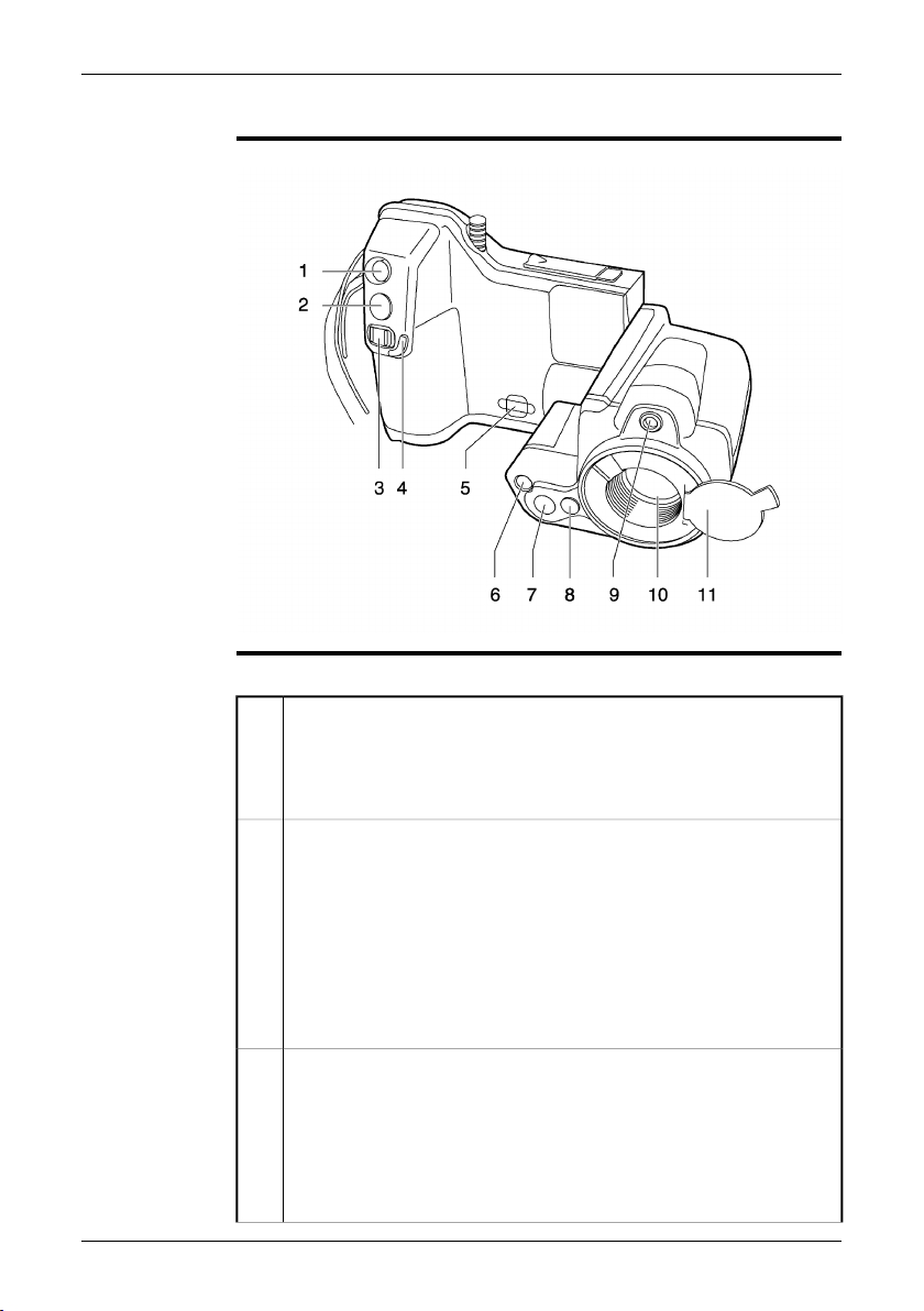
9.3 View of the bottom side
9 – Camera parts
Figure
Explanation
10759103;a1
This table explains the figure above:
Tripod mount 1/4"-201
Release button for the cover to the connector bay2
Cover for the connector bay3
Release button for the battery compartment cover4
Cover for the battery compartment5
Publ. No. 1558792 Rev. a379 – ENGLISH (EN) – August 14, 2009 15
Page 28
9 – Camera parts
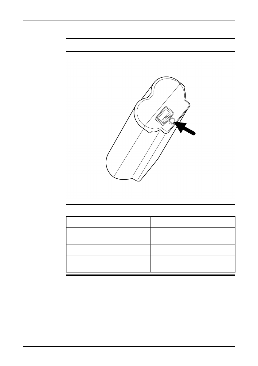
9.4 Battery condition indicator
General
Figure
Explanation
The battery has a battery condition indicator.
10715703;a3
This table explains the battery condition indicator:
ExplanationType of signal
The green light flashes.
The green light is off.
The power supply or the stand-alone
battery charger is charging the battery.
The battery is fully charged.The green light is continuous.
The camerais usingthebattery (instead
of the power supply).
16 Publ. No. 1558792 Rev. a379 – ENGLISH (EN) – August 14, 2009
Page 29
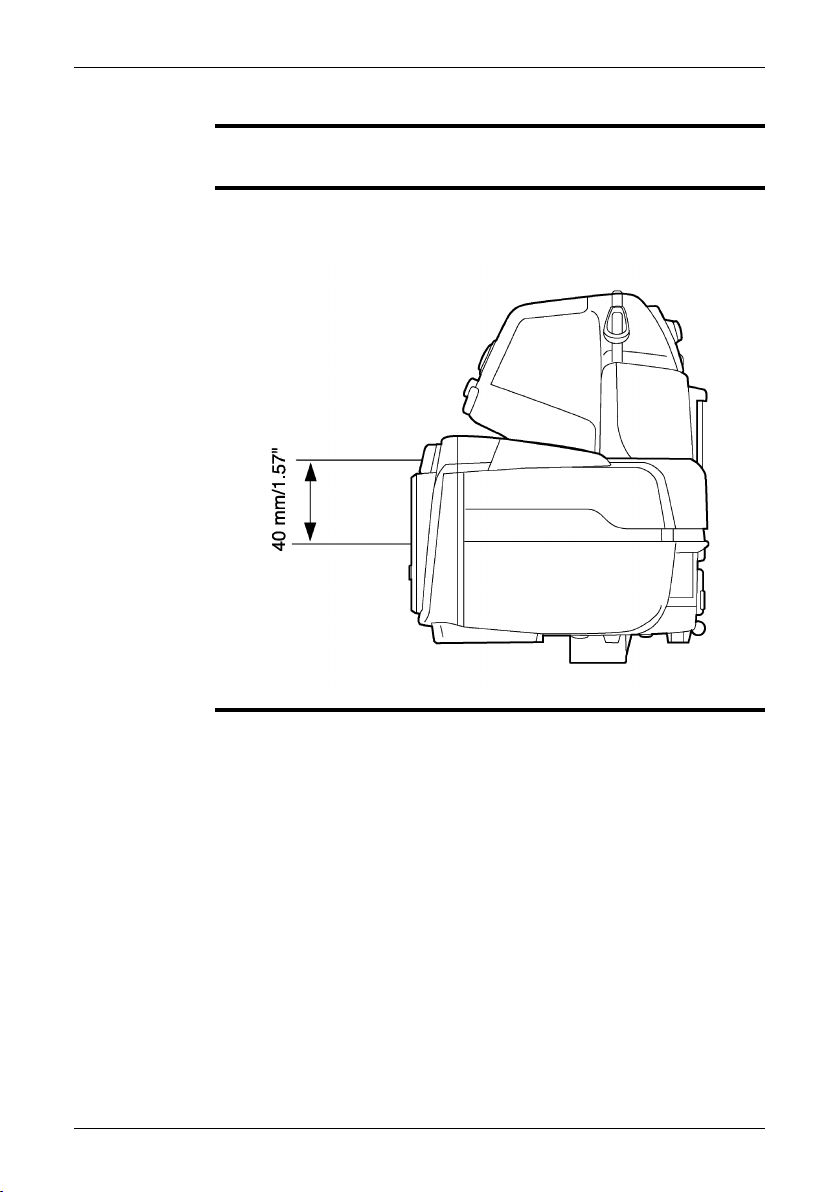
9.5 Laser pointer
9 – Camera parts
General
Figure
The camera has a laser pointer. When the laser pointer is on, you can see a laser
dot approximately 40 mm (1.57 in.) above the target.
This figure showsthe difference in position between the laser pointer and the optical
center of the infrared lens:
10759203;a1
Publ. No. 1558792 Rev. a379 – ENGLISH (EN) – August 14, 2009 17
Page 30

9 – Camera parts
WARNING
CAUTION
NOTE
Laser warning
label
Laser rules and
regulations
Do not look directly into the laser beam. The laser beam can cause eye irritation.
Protect the laser pointer with the protective cap when you are not using the laser
pointer.
A laser warning symbol is displayed on the screen when the laser pointer is on.
■
The laser pointer may not be enabled in all markets.
■
A laser warning label with the following information is attached to the camera:
10743603;a2
Wavelength: 635 nm. Max. output power: 1 mW.
This product complies with 21 CFR 1040.10 and 1040.11 except for deviations pur-
suant to Laser Notice No. 50, dated June 24, 2007.
18 Publ. No. 1558792 Rev. a379 – ENGLISH (EN) – August 14, 2009
Page 31

10 Toolbars and work areas
10.1 Work areas
10.1.1 Operation mode area
The operation mode area becomes visible when you push the Mode button.
NOTE
■
To navigate in the area, use either the joystick or the stylus pen.
■
Figure
Explanation
10765803;a3
This table explains the figure above:
Camera mode
1
This is the most commonly used operation mode of the camera.
You select this mode to save an infrared image to the SD Memory Card.
If you push and hold down the Preview/Save button for more than one
second, the documentation toolbar will be displayed.
Publ. No. 1558792 Rev. a379 – ENGLISH (EN) – August 14, 2009 19
Page 32

10 – Toolbars and work areas
2
3
4
5
Video mode
If you select this mode, you can record video clips with the camera. You
start and stop the recording by pushing the Preview/Save button.
For more information about this, see section 10.2.5 – Video recording
toolbar on page 33 and section 16 – Recording video clips on page 78.
Simultaneous snapshot mode
If you select this mode, and briefly push the Preview/Save button, the
camera will automatically save a digital photo at the same time as it saves
the infrared image.
Note: The simultaneous snapshot mode only works when you take an infrared image. If you take a digital photo, no infrared image will be saved.
Program mode
If you select this mode, you can periodically save images at a specified
time interval.
Panorama mode
If you select this mode, you can create large images by stitching normal
images together.
20 Publ. No. 1558792 Rev. a379 – ENGLISH (EN) – August 14, 2009
Page 33

10.1.2 Main work area
10 – Toolbars and work areas
Figure
Explanation
10760703;a1
This table explains the figure above:
Measurement results table (in ℃ or ℉, depending on the settings)1
Measurement menu.
2
To open and close this menu, push the Measure button.
Indicator for the automatic adjustment mode or the manual adjustment
3
mode (A/M)
Spotmeter4
Temperature scale5
Measurement area6
Limit indicator for the temperature scale7
Publ. No. 1558792 Rev. a379 – ENGLISH (EN) – August 14, 2009 21
Page 34

10 – Toolbars and work areas
10.1.3 Sketch work area
The sketchwork area becomesvisible when youadd a sketchto an infraredimage.
NOTE
■
You do this from the documentation toolbar.
To navigate in the area, use either the joystick or the stylus pen.
■
To draw the sketch, use the stylus pen.
■
Figure
Explanation
10762203;a1
This table explains the figure above:
Canvas
1
You draw your sketch in this area, using the stylus pen.
OK button
2
You select this button to confirm the sketch and leave the sketch mode.
Clear button
3
You select this button to clear the whole canvas.
Pen button
4
You select this button to enable the pen.
Eraser button
5
You select this button to enable the eraser.
Color palette
6
You select this color swatch to switch between colors.
22 Publ. No. 1558792 Rev. a379 – ENGLISH (EN) – August 14, 2009
Page 35

10 – Toolbars and work areas
SEE ALSO
For informationabout adding asketch to aninfrared image, see section 18.5– Adding
a sketch on page 98.
Publ. No. 1558792 Rev. a379 – ENGLISH (EN) – August 14, 2009 23
Page 36

10 – Toolbars and work areas
10.1.4 Text annotation and image description work area
The text annotation and image description work area becomes visible when you
NOTE
■
add a text annotation or an image description to an infrared image. You do this
from the documentation toolbar. To display the documentation toolbar, push and
hold down the Save/Preview button for more than two seconds.
To navigate in the area, use either the joystick or the stylus pen.
■
Figure
Explanation
This figure shows the text annotation work area:
10765603;a2
This table explains the figure above:
OK button
1
You select this button to confirm and save the text annotation.
Tab for the text annotation work area (to select from pre-defined strings)2
Tab for the image description work area (to enter the free text mode, using
3
the stylus pen)
Filename indicator for the text annotation file4
Text annotation label5
Text annotation value6
Submenu displaying additional text annotation values7
24 Publ. No. 1558792 Rev. a379 – ENGLISH (EN) – August 14, 2009
Page 37

10 – Toolbars and work areas
Keyboard button
8
You select this button to go to the keyboard and enter text using the stylus
pen.
Clear button
9
You select this button to clear all input data from the selected tab.
SEE ALSO
For informationabout adding atext annotation to an infraredimage, see section18.3
– Adding a text annotation on page 94.
Publ. No. 1558792 Rev. a379 – ENGLISH (EN) – August 14, 2009 25
Page 38

10 – Toolbars and work areas
Figure
Explanation
This figure shows the image description work area:
10765703;a1
This table explains the figure above:
OK button
1
You select this button to confirm and save the text annotation.
Tab for the text annotation work area (to select from pre-defined strings)2
Tab for the image description work area (to enter the free text mode, using
3
the stylus pen)
Preview window for the image description4
Keyboard5
Clear button
6
You select this button to clear all input data from the selected tab.
SEE ALSO
For information about adding an image description to an infrared image, see section
18.4 – Adding an image description on page 97.
26 Publ. No. 1558792 Rev. a379 – ENGLISH (EN) – August 14, 2009
Page 39

10.2 Toolbars
10.2.1 Measurement toolbar
The measurement toolbar becomes visible when you push the Measure button
NOTE
■
and select Advanced.
You use the measurement toolbar to set up measurement tools in the advanced
■
mode, or when editing a saved image in the archive mode.
To navigate on the toolbar, use either the joystick or the stylus pen.
■
10 – Toolbars and work areas
Figure
Explanation
10760803;a3
This table explains the figure above:
You select this toolbar button to do one or more of the following:
1
Move measurement tools
■
Remove measurement tools
■
Turn on and turn off alarms (only for spotmeters and areas).
■
Set alarm levels (only for spotmeters and areas).
■
Isotherm toolbar button
2
You select this toolbar button to set up different types of isotherms. The
isotherm command colors all pixels with a temperature above, below, or
between one or more preset temperature levels.
Spotmeter toolbar button
3
You select this toolbar button to create a spotmeter.
Area toolbar button
4
You select this toolbar button to create a measurement area.
Difference calculation toolbar button
5
You select this toolbar button to set up a difference calculation.
Object parameters toolbar button
6
You select this toolbar button to change object parameters. Setting the
correct object parameters is important if precise measurement results are
required.
Publ. No. 1558792 Rev. a379 – ENGLISH (EN) – August 14, 2009 27
Page 40

10 – Toolbars and work areas
7
OK toolbar button
You use this button if you arrive at this toolbar from the documentation
toolbar. Selecting this toolbar button after you have changed the desired
parameter returns you to the documentation toolbar.
This toolbar button will only be displayed if you arrive at this toolbar from
the documentation toolbar.
28 Publ. No. 1558792 Rev. a379 – ENGLISH (EN) – August 14, 2009
Page 41

10.2.2 Documentation toolbar
The documentationtoolbarbecomesvisible when you previewanimage, or when
NOTE
■
you edit an image from the image archive.
To preview an image, push and hold down the Save button for more than one
■
second.
To navigate on the toolbar, use either the joystick or the stylus pen.
■
10 – Toolbars and work areas
Figure
Explanation
10760903;a2
This table explains the figure above:
Delete image toolbar button
1
You select this toolbar button to discard the image that you are previewing.
Add markers toolbar button
2
You select this tool to add arrow markers to points of interest in an infrared
image. The arrow marker will be saved in the infrared image.
Measurement toolbar button
3
You select thistool to goto the measurementtoolbar, whereyou canchange
a variety of parameters before you save the image.
Add sketch toolbar button
4
You select thistoolbar button to add afreehand sketch toan infraredimage.
The sketch will be linked to the infrared image.
Add voice annotation toolbar button
5
You select thistoolbar button to add avoice annotation toan infrared image.
The voice annotation will be saved in the infrared image.
Add text annotation toolbar button
6
You select this toolbarbuttonto add text annotationsand/orimage descriptions to an infrared image. Text annotations and image descriptions will be
saved in the infrared image.
Add digital photo toolbar button
7
You select this toolbar button to add a digital photo to the infrared image.
The digital photo will be linked to the infrared image.
Publ. No. 1558792 Rev. a379 – ENGLISH (EN) – August 14, 2009 29
Page 42

10 – Toolbars and work areas
8
Save toolbar button
You select this toolbar button to save the infrared image after you have
added any of the previous five annotations. If you have opened an image
from the image archive, this toolbar button says Close instead of Save.
30 Publ. No. 1558792 Rev. a379 – ENGLISH (EN) – August 14, 2009
Page 43

10.2.3 Image marker toolbar
The image marker toolbar becomes visible when you add an image marker. You
NOTE
■
do this from the documentation toolbar.
To navigate on the toolbar, use either the joystick or the stylus pen.
■
10 – Toolbars and work areas
Figure
Explanation
10762303;a2
This table explains the figure above:
You select this toolbar button to move and remove any markers you have
1
previously added to the image.
Marker toolbar button
2
You select this toolbar button to create a marker. Tap gently on the toolbar
button using the stylus pen, and then draw a line on the image.
OK toolbar button
3
You select this toolbar button to confirm any markers you have added to
the image before leaving this work mode.
Publ. No. 1558792 Rev. a379 – ENGLISH (EN) – August 14, 2009 31
Page 44

10 – Toolbars and work areas
10.2.4 Voice annotation toolbar
The voice annotation toolbarbecomes visible whenyou record orlisten to a voice
NOTE
■
comment. You do this from the documentation toolbar.
To navigate on the toolbar, use either the joystick or the stylus pen.
■
Some buttons have more than one function, and the symbols on the buttons will
■
change depending on the context.
Figure
Explanation
10763803;a2
This table explains the figure above:
Discard recording toolbar button
1
You select this toolbar button to delete a voice comment that you have
made.
Adjust volume toolbar button
2
You select this toolbar button and move the joystick up/down to adjust the
volume when you play back voice comments.
Start/stop recording toolbar button
3
You select this toolbar button to start and stop the recording of a voice
comment.
Start/stop playback toolbar button
4
You select this toolbar button to start and stop the playback of a previously
recorded voice comment.
Go to beginning toolbar button
5
You select this toolbar button to go back to the beginning of the recording.
OK toolbar button
6
You select this toolbar button to confirm and save the previously recorded
voice comment.
Time indicator (X/Y seconds, where X = elapsed recording time and Y =
7
total recording time)
32 Publ. No. 1558792 Rev. a379 – ENGLISH (EN) – August 14, 2009
Page 45

10.2.5 Video recording toolbar
The video recording toolbar becomes visible when you have recorded a video
NOTE
■
clip
To navigate on the toolbar, use either the joystick or the stylus pen.
■
Some buttons have more than one function, and the symbols on the buttons will
■
change depending on the context.
10 – Toolbars and work areas
Figure
Explanation
T630231;a2
This table explains the figure above:
Discard recording toolbar button
1
You select this toolbar button to delete the video recording that you have
made.
Start/stop playback toolbar button
2
You select this toolbar button to start and stop the playback of the video
recording.
Go to beginning toolbar button
3
You select this toolbar button to go back to the beginning of the recording.
OK toolbar button
4
You select this toolbar button to confirm and save the recorded video
recording that you have made.
Time indicator (X/Y seconds, where X = elapsed recording time and Y =
5
total recording time)
SEE ALSO
For more information about this, see section 10.1.1 – Operation mode area on page
19 and section 16 – Recording video clips on page 78.
Publ. No. 1558792 Rev. a379 – ENGLISH (EN) – August 14, 2009 33
Page 46

10 – Toolbars and work areas
10.2.6 Periodic save toolbar
The periodic save toolbar becomes visible when you go to Program mode.
NOTE
■
To navigate on the toolbar, use either the joystick or the stylus pen.
■
Figure
Explanation
SEE ALSO
T630370;a1
This table explains the figure above:
Setup toolbar button
1
You select this toolbar button to set up the camera for periodic saving.
Start periodic save toolbar button
2
You select this toolbar button to start the periodic save.
For more information about this, see section 14.4 – Periodically saving an image on
page 60.
34 Publ. No. 1558792 Rev. a379 – ENGLISH (EN) – August 14, 2009
Page 47

10.2.7 Work folder toolbar
The work folder toolbar becomes visible when you select a work folder in Setup
NOTE
■
mode.
To navigate on the toolbar, use either the joystick or the stylus pen.
■
10 – Toolbars and work areas
Figure
Explanation
SEE ALSO
T630371;a1
This table explains the figure above:
Create new folder toolbar button1
Delete folder toolbar button2
Close toolbar button3
For moreinformation about this,see section 14.11– Working withfolders on page 70.
Publ. No. 1558792 Rev. a379 – ENGLISH (EN) – August 14, 2009 35
Page 48

11 Navigating the menu system
Figure
Explanation
10763703;a1 10763603;a1
The figure above shows the two ways to navigate the menu system in the camera:
Using the stylus pen to navigate the menu system (left).
■
Using the joystick to navigate the menu system (right).
■
You can also use a combination of the two.
In this manual it is assumed that the joystick is used, but most tasks can also be
carried out using the stylus pen.
36 Publ. No. 1558792 Rev. a379 – ENGLISH (EN) – August 14, 2009
Page 49

12 External devices and storage
media
General
You can connect the following external devices and storage media to the camera:
A power supply.
■
A video monitor.
■
A computer to move images and other files to and from the camera.
■
An external USB device, such as a USB keyboard or USB memory stick.
■
A headset to record and listen to voice comments.
■
One SD Memory Card.
■
Publ. No. 1558792 Rev. a379 – ENGLISH (EN) – August 14, 2009 37
Page 50

12 – External devices and storage media
12.1 Connecting external devices
Figure
Explanation
10759303;a2
This table explains the figure above:
To connect a headset to the camera to record and listen tovoice comment,
1
use a headset cable and this socket.
To connect a video monitor to the camera, use a CVBS cable (a composite
2
video cable) and this socket.
To connect a computer to thecamera tomove images and files toand from
3
the camera, use a USB Mini-B cable and this socket.
To connect an external USB device to the camera, use a USB-A cable and
4
this socket.
38 Publ. No. 1558792 Rev. a379 – ENGLISH (EN) – August 14, 2009
Page 51

12.2 Inserting SD Memory Cards
12 – External devices and storage media
Figure
Procedure
10759503;a1
Follow this procedure to insert an SD Memory Card:
Open the rubber cover that protects the card slot.1
Push the SD Memory Card firmly into the card slot, until a clicking sound
2
is heard.
Publ. No. 1558792 Rev. a379 – ENGLISH (EN) – August 14, 2009 39
Page 52

13 Handling the camera
13.1 Charging the battery
NOTE
General
SEE
You must charge the battery for four hours before you start using the camera for the
first time.
You must charge the battery when a low battery voltage warning is displayed on the
screen.
Follow one of these procedures to charge the battery:
Use the combined power supply and battery charger to charge the battery when
■
it is inside the camera.
Use the combined power supply and battery charger to charge the battery when
■
it is outside the camera.
Use the stand-alone battery charger to charge the battery
■
For information on how to charge the battery, see the following sections:
Section 13.1.1 – Usingthe combined powersupply and battery charger tocharge
■
the battery when it is inside the camera on page 41
Section 13.1.2 – Usingthe combined powersupply and battery charger tocharge
■
the battery when it is outside the camera on page 42
Section 13.1.3 – Using the stand-alone battery charger to charge the battery on
■
page 43
40 Publ. No. 1558792 Rev. a379 – ENGLISH (EN) – August 14, 2009
Page 53

13 – Handling the camera
13.1.1 Using the combined power supply and battery charger to charge the battery when it is inside the camera
NOTE
Procedure
SEE ALSO
For brevity, the ‘combined power supply and battery charger’ is called the ‘power
supply’ below.
Follow this procedure to use the power supply to charge the batterywhen it is inside
the camera:
Open the battery compartment lid.1
Connect the power supply cable plug to the connector on the battery.2
Connect the power supply mains-electricity plug to a mains socket.3
Disconnect thepower supply cable plug whenthe green lightof the battery
4
condition indicator is continuous.
For information about the battery condition indicator, see section 9.4 – Battery condition indicator on page 16.
Publ. No. 1558792 Rev. a379 – ENGLISH (EN) – August 14, 2009 41
Page 54

13 – Handling the camera
13.1.2 Using the combined power supply and battery charger to charge the battery when it is outside the camera
NOTE
Procedure
SEE ALSO
For brevity, the ‘combined power supply and battery charger’ is called the ‘power
supply’ below.
Follow thisprocedure to usethe powersupply to chargethe battery when it isoutside
the camera:
Put the battery on a flat surface.1
Connect the power supply cable plug to the connector on the battery.2
Connect the power supply mains-electricity plug to a mains socket.3
Disconnect thepower supply cable plug whenthe green lightof the battery
4
condition indicator is continuous.
For information about the battery condition indicator, see section 9.4 – Battery condition indicator on page 16.
42 Publ. No. 1558792 Rev. a379 – ENGLISH (EN) – August 14, 2009
Page 55

13 – Handling the camera
13.1.3 Using the stand-alone battery charger to charge the battery
Procedure
SEE ALSO
Follow this procedure to use the stand-alone battery charger to charge the battery:
Put the battery in the stand-alone battery charger.1
Connect the power supply cable plug to the connector on the stand-alone
2
battery charger.
Connect the power supply mains-electricity plug to a mains socket.3
Disconnect thepower supply cable plug whenthe green lightof the battery
4
condition indicator is continuous.
For information about the battery condition indicator, see section 9.4 – Battery condition indicator on page 16.
Publ. No. 1558792 Rev. a379 – ENGLISH (EN) – August 14, 2009 43
Page 56

13 – Handling the camera
13.2 Inserting the battery
NOTE
Procedure
Use a clean, drycloth to removeany water ormoisture on the battery beforeyou insert
it.
Follow this procedure to insert the battery:
Push the release button on the battery compartment cover to unlock it.
1
10759603;a1
Open the cover to the battery compartment.
2
10759703;a1
Push the battery into the battery compartment until the battery locking
3
mechanism engages.
10759803;a1
44 Publ. No. 1558792 Rev. a379 – ENGLISH (EN) – August 14, 2009
Page 57

Close the cover to the battery compartment.
4
10759903;a1
13 – Handling the camera
Publ. No. 1558792 Rev. a379 – ENGLISH (EN) – August 14, 2009 45
Page 58

13 – Handling the camera
13.3 Removing the battery
Procedure
Follow this procedure to remove the battery:
Push the release button on the battery compartment cover to unlock it.
1
10759603;a1
Open the cover to the battery compartment.
2
10763903;a1
Push the red release button in the direction of the arrow to unlock the bat-
3
tery.
10760003;a2
46 Publ. No. 1558792 Rev. a379 – ENGLISH (EN) – August 14, 2009
Page 59

Pull out the battery from the battery compartment.
4
10760103;a1
13 – Handling the camera
Publ. No. 1558792 Rev. a379 – ENGLISH (EN) – August 14, 2009 47
Page 60

13 – Handling the camera
13.4 Turning on the camera
Procedure
To turn on the camera, push and release the On/Off button.
13.5 Turning off the camera
Procedure
To turn off thecamera, push andhold down the On/Off buttonfor more than2 second.
13.6 Entering standby mode
Procedure
To enter the standby mode, push and hold down the On/Off button for approx. 0.2
seconds.
13.7 Exiting standby mode
Procedure
To exit the standby mode, push and hold down the On/Off button for approx. 0.2
seconds.
48 Publ. No. 1558792 Rev. a379 – ENGLISH (EN) – August 14, 2009
Page 61

13.8 Adjusting the angle of lens
13 – Handling the camera
General
Figure
Procedure
To make your working position as comfortable as possible, you can adjust the angle
of the lens.
10760203;a1
To adjust the angle, tilt the lens up or down.
Publ. No. 1558792 Rev. a379 – ENGLISH (EN) – August 14, 2009 49
Page 62

13 – Handling the camera
13.9 Mounting an additional infrared lens
NOTE
Procedure
Do nottouchthe lens surfacewhenyou mount an infraredlens. If this happens,clean
the lens according to the instructions in section 20.2 – Infrared lens on page 104.
Follow this procedure to mount an additional infrared lens:
Push the lens release button to unlock the lens cap.
1
10764003;a1
Rotate the lens cap 30° counter-clockwise (looking at the front of the lens).
2
10764103;a1
Carefully pull out the lens cap from the bayonet ring.
3
10764203;a1
50 Publ. No. 1558792 Rev. a379 – ENGLISH (EN) – August 14, 2009
Page 63

Correctly position the lens in front of the bayonet ring.
4
10764303;a1
Carefully push the lens into position.
5
10764403;a1
Rotate the lens 30° clockwise (looking at the front of the lens).
6
10764503;a1
13 – Handling the camera
Publ. No. 1558792 Rev. a379 – ENGLISH (EN) – August 14, 2009 51
Page 64

13 – Handling the camera
13.10 Removing an additional infrared lens
Do not touch the lens surface when you remove an infrared lens. If this happens,
NOTE
■
clean the lens according to the instructions in section 20.2 – Infrared lens on
page 104.
When you have removed the lens, put the lens caps on the lens immediately, to
■
protect it from dust and fingerprints.
Procedure
Follow this procedure to remove an additional infrared lens:
Push the lens release button to unlock the lens.
1
10764603;a1
Rotate the lens counter-clockwise 30° (looking at the front of the lens).
2
10764703;a1
Carefully pull out the lens from the bayonet ring.
3
10764803;a1
52 Publ. No. 1558792 Rev. a379 – ENGLISH (EN) – August 14, 2009
Page 65

13 – Handling the camera
Correctly position the lens cap in front of the bayonet ring.
4
10764903;a1
Carefully push the lens cap into position.
5
10765003;a1
Rotate the lens cap 30° clockwise (looking at the front of the lens).
6
10765103;a1
Publ. No. 1558792 Rev. a379 – ENGLISH (EN) – August 14, 2009 53
Page 66

13 – Handling the camera
13.11 Attaching the sunshield
General
Procedure
You can attach a sunshield to the camera to make the LCD screen easier to see in
sunlight.
Follow this procedure to attach the sunshield to the camera:
Align the two front tabs of the sunshield with the corresponding two
1
notches at the top of the screen.
10765203;a1
Push the front part of the sunshield into position. Make sure that the two
2
tabs mate with the corresponding notches.
10765303;a1
Carefully hold together the two rear wings of the sunshield.
3
10765403;a1
54 Publ. No. 1558792 Rev. a379 – ENGLISH (EN) – August 14, 2009
Page 67

13 – Handling the camera
Push the rear part of the sunshield toward the screen, and then release
4
your grip. Make surethat the twotabs mate withthe corresponding notches.
10765503;a1
Publ. No. 1558792 Rev. a379 – ENGLISH (EN) – August 14, 2009 55
Page 68

13 – Handling the camera
13.12 Using the laser pointer
Figure
Procedure
10760303;a1
Follow this procedure to use the laser pointer:
To turn on the laser pointer, push and hold the laser pointer button.1
To turn off the laser pointer, release the laser pointer button.2
NOTE
The laser pointer may not be enabled in all markets.
56 Publ. No. 1558792 Rev. a379 – ENGLISH (EN) – August 14, 2009
Page 69

14 Working with images and folders
14.1 Adjusting the infrared camera focus
Procedure
NOTE
To adjust the infrared camera focus, do one of the following:
Push the focus button left for far focus.
■
Push the focus button right for near focus.
■
Briefly push the focus button toward the camera button to autofocus.
■
It is important that you hold the camera steady while autofocusing.
Publ. No. 1558792 Rev. a379 – ENGLISH (EN) – August 14, 2009 57
Page 70

14 – Working with images and folders
14.2 Previewing an image
General
Procedure
SEE ALSO
In preview mode, you can add various types of annotations to the image before you
save it. You do this by using thedocumentation toolbar thatis automatically displayed
when you preview an image.
In preview mode youcan also checkthat the imagecontains the required information
before you save it to the SD Memory Card.
To preview an image, push and hold down the Preview/Save button for more than
one second.
For more information about the documentation toolbar, see section 10.2.2 –
■
Documentation toolbar on page 29.
For more information about adding annotations, see section 18 – Annotating im-
■
ages on page 91.
58 Publ. No. 1558792 Rev. a379 – ENGLISH (EN) – August 14, 2009
Page 71

14.3 Saving an image
14 – Working with images and folders
General
Formatting
memory cards
Image capacity
Procedure
You can save one or more images to the SD Memory Card.
For best performance, memory cards should be formatted to the FAT (FAT16) file
system. Using FAT32-formatted memory cards may result in inferior performance.
To format a memory card to FAT (FAT16), follow this procedure:
Insert the memory card into a card reader that is connected to your com-
1
puter.
In Windows®Explorer, select My Computer and right-click the memory
2
card.
Select Format.3
Under File system, select FAT.4
Click Start.5
This table gives information on theapproximate number of images that can be saved
on SD Memory Cards:
No voice annotationCard size
To save an image without previewing, briefly push the Preview/Save button.
Incl. 30 seconds voice
annotation
250500256 MB
5001000512 MB
100020001 GB
Publ. No. 1558792 Rev. a379 – ENGLISH (EN) – August 14, 2009 59
Page 72

14 – Working with images and folders
14.4 Periodically saving an image
General
Procedure
You can periodically save images at a specified time interval.
Follow this procedure to periodically save an image:
Push the Mode button.1
Use the joystick to select Program.2
Push the joystick.3
4
Move the joystick to the toolbar button, then push the joystick. This
will display a setup menu.
Use the joystick to set the desired parameters.5
6
To start the periodic save, move the joystick to the toolbar button, then
push the joystick. The periodic save has now started, and the following
toolbar is displayed:
T630366;a1
7
To stop the recording, move the joystick to the toolbar button, then
push the joystick.
60 Publ. No. 1558792 Rev. a379 – ENGLISH (EN) – August 14, 2009
Page 73

14.5 Opening an image
14 – Working with images and folders
General
Procedure
NOTE
When you save an image, it is stored on the SD Memory Card. To display the image
again, you can recall it from the SD Memory Card.
Follow this procedure to open an image:
Push the Archive button to open the most recently saved image.1
If you want to open another image, do one of the following:
2
1 Move the joystick upwards. Thiswill display theimages as thumbnails.
■
2 Select the image you want to open by using the joystick.
3 Push the Select button to open this image.
Move the joystick left/right. This will display the next/previous image in
■
the full image mode.
To leave archive mode, push the Archive button.
Publ. No. 1558792 Rev. a379 – ENGLISH (EN) – August 14, 2009 61
Page 74

14 – Working with images and folders
14.6 Using the Panorama function
General
NOTE
Procedure
The camera has a Panorama function. Thismeans thatyou can create larger images
by stitching normal images together.
The images are storedin the camerausing a special mode. Theactual stitching takes
place in FLIR Systems PC software for post-processing, for example FLIR Reporter
or .
When you enter this mode, all graphics are removed from the screen.
■
When you enter thismode, all measurementtools are disabled,but will beenabled
■
when you leave the mode.
In thumbnail view, the images that are createdusing this function display the icon
■
.
To create a Panorama image, follow this procedure:
Push the Mode button.1
Use the joystick to select Panorama.2
Push the joystick. This will display the following screen:
3
T630364;a1
The screen is divided into nine areas using four guidelines. In the tools
pane, a blue rectangle indicates which section of the screen you will save
when saving an image at this time.
Note that the guidelines are only intended as an aid when you move the
camera to the next area for which you want to save an image. Thus, the
guidelines make it easy for you to align the images.
62 Publ. No. 1558792 Rev. a379 – ENGLISH (EN) – August 14, 2009
Page 75

14 – Working with images and folders
To save an image, push the Preview/Save button.
4
The saved image will now be displayed in the corresponding area in the
tools pane. You can also see that the left-most area on the screen shows
the image you just saved (indicated here in red):
T630365;a1
Using the joystick, you can now decide in which area you want to save the
5
next image, and then save the image by pushing the Preview/Save button.
Continue usingthis procedureuntil you havecreated your completeimage.
To finish and leave this mode, push the Mode button.6
Publ. No. 1558792 Rev. a379 – ENGLISH (EN) – August 14, 2009 63
Page 76

14 – Working with images and folders
14.7 Adjusting an image manually
General
Example 1
An image can be adjusted automatically or manually.
These two modes are indicated in the top right corner of the screen by the letters A
and M. You use the A/M button to switch between these two modes
This figure shows two infrared images of cable connection points. In the left image
a correct analysis of the circled cable is difficult if you only auto-adjust the image.
You can analyze this cable in more detail if you
change the temperature scale level
■
change the temperature scale span.
■
In the left image, the image is auto-adjusted. In the right image the maximum and
minimum temperaturelevels have beenchangedto temperaturelevelsnear the object.
On the temperature scale to the rightof each imageyou can seehow thetemperature
levels were changed.
10577503;a2
64 Publ. No. 1558792 Rev. a379 – ENGLISH (EN) – August 14, 2009
Page 77

14 – Working with images and folders
Example 2
This figure shows two infrared images of an isolator in a power line.
In the left image,the cold sky and thepower line structureare recordedat a minimum
temperature of –26.0°C (–14.8°F). In the right image the maximum and minimum
temperature levels have been changed to temperature levels near the isolator. This
makes it easier to analyze the temperature variations in the isolator.
10742503;a3
Publ. No. 1558792 Rev. a379 – ENGLISH (EN) – August 14, 2009 65
Page 78

14 – Working with images and folders
Changing
temperature the
scale level
Changing
temperature the
scale span
Follow this procedure to change the temperature scale level:
1 Make sure that the camera displays a live infrared image. To do this, select
Camera mode using the Mode button and the joystick.
Make sure that the camera is in the manual adjustment mode. This is indi-
2
cated by the letter M in the top right corner of the screen. If not, push the
A/M button once.
To change the temperature scale level, move the joystick up/down. Note
3
that this changes both the minimum and maximum scale leveltemperature
by the same amount.
Follow this procedure to change the temperature scale span:
1 Make sure that the camera displays a live infrared image.
Make sure that the camera is in the manual adjustment mode. This is indi-
2
cated by the letter M in the top right corner of the screen. If not, push the
A/M button once.
To change the temperature scale span, move the joystick left/right.3
66 Publ. No. 1558792 Rev. a379 – ENGLISH (EN) – August 14, 2009
Page 79

14.8 Hiding overlay graphics
14 – Working with images and folders
General
Procedure
Overlay graphics provide information about an image. You can choose to hide
overlay graphics incrementally in steps.
To hide overlay graphics in steps, push the Info button.
Publ. No. 1558792 Rev. a379 – ENGLISH (EN) – August 14, 2009 67
Page 80

14 – Working with images and folders
14.9 Deleting an image
General
Procedure
You can delete one or more images from the SD Memory Card.
Follow this procedure to delete an image:
Push the Archive button.1
Do one of the following:
2
Move the joystick left/right to select the image you want to delete, then
■
go to Step 5 below.
Move the joystick upwards to display the images as thumbnails, then
■
go to Step 3 below.
Select the image you want to delete by using the joystick.3
Push the joystick to open the image.4
Push the joystick to display a menu.5
On the menu, select Delete image by using the joystick.6
Push the joystick to confirm.7
68 Publ. No. 1558792 Rev. a379 – ENGLISH (EN) – August 14, 2009
Page 81

14.10 Deleting all images
14 – Working with images and folders
General
Procedure
You can delete all images from the SD Memory Card.
Follow this procedure to delete all images:
Push the Archive button.1
Push the joystick to display a menu.2
On the menu, select Delete all by using the joystick.3
Push the joystick to confirm.4
Publ. No. 1558792 Rev. a379 – ENGLISH (EN) – August 14, 2009 69
Page 82

14 – Working with images and folders
14.11 Working with folders
General
Procedure
You can arrange your images in different folders, and delete folders that you do not
use.
Follow this procedure to create a new folder:
Push the Setup button.1
Go to the Camera tab.2
Select Work folder.3
Push the joystick.4
5
To create a new folder, move the joystick to the right to select the
toolbar button, then push the joystick. A new folder has now been created.
Push the Mode button to leave the dialog box.6
70 Publ. No. 1558792 Rev. a379 – ENGLISH (EN) – August 14, 2009
Page 83

14 – Working with images and folders
Procedure
Follow this procedure to delete a folder:
Push the Setup button.1
Go to the Camera tab.2
Select Work folder.3
Push the joystick.4
To delete a folder, select the folder using the joystick.5
6
Move the joystick to the right to select the toolbar button, then push
the joystick. The folder has now been deleted.
Push the Mode button to leave the dialog box.7
Publ. No. 1558792 Rev. a379 – ENGLISH (EN) – August 14, 2009 71
Page 84

14 – Working with images and folders
Procedure
Follow this procedure to set a folder as a work folder:
Push the Setup button.1
Go to the Camera tab.2
Select Work folder.3
Push the joystick.4
(This step assumes that you have more than one work folder.)
5
To set another folder as a work folder, select the folder using the joystick,
then push the joystick. The new folder is now set as a work folder.
Push the Mode button to leave the dialog box.6
72 Publ. No. 1558792 Rev. a379 – ENGLISH (EN) – August 14, 2009
Page 85

15 Working with fusion
What is fusion?
Fusion types
Fusion is a function that lets you display part of a digital photo as an infrared image.
For example, you can set the camera to display all areas of an image that have a
certain temperature in infrared, with all other areas displayed as a digital photo. You
can also set the camera to display an infrared image frame on top of a digital photo.
You can thenmove aroundthe infrared image frame, orchange the size of theimage
frame.
Depending oncamera model, upto four different types offusion are available.These
are:
Above: All areas in the digital photo with a temperature above the specified tem-
■
perature level are displayed in infrared.
Below: All areas in the digital photo with a temperature below the specified tem-
■
perature level are displayed in infrared.
Interval: All areas in the digital photo with a temperature between two specified
■
temperature levels are displayed in infrared.
Picture in Picture: An infrared image frame is displayed on top of the digital
■
photo.
Publ. No. 1558792 Rev. a379 – ENGLISH (EN) – August 14, 2009 73
Page 86

15 – Working with fusion
Image examples
This table explains the four different types of fusion:
ImageFusion type
Above
Below
Interval
Picture in Picture
74 Publ. No. 1558792 Rev. a379 – ENGLISH (EN) – August 14, 2009
Page 87

15 – Working with fusion
General
How to set up a
fusion type
Before you can activate fusion, you must set up a fusion type.
Follow this procedure to set up a fusion type:
1 Push the Setup button.
On the menu, select Fusion, using the joystick.2
Push the joystick.3
In the Fusion box, select one of the following:
4
Above
■
Below
■
Interval
■
Picture in Picture
■
Push the joystick to confirm the choice.5
Push the Setup button.6
Publ. No. 1558792 Rev. a379 – ENGLISH (EN) – August 14, 2009 75
Page 88

15 – Working with fusion
Do one or more of the following:
7
If you chose Above or Below, move the joystick up or down to adjust
■
the temperature level. The temperature level is displayed as a 'flag' that
slides along the temperature scale. See the figure below.
If you chose Interval, do one or more of the following:
■
Push the joystick up/down to move the interval up/down.
■
Push the joystick left/right to increase/decrease the interval.
■
If you chose Picture in Picture, do one or more of the following:
■
Push the joystick once. This displays a blue indicator in the middle
■
of the infrared image frame. You can now use the joystick to move
the image frame. See the figure below.
Push the joystick twice. This displays four blue indicators around the
■
infrared imageframe. You can nowuse the joystickto resize theimage
frame. See the figure below.
To deactivate Fusion, repeat Step 4 above and select Off.8
76 Publ. No. 1558792 Rev. a379 – ENGLISH (EN) – August 14, 2009
Page 89

15 – Working with fusion
General
How to activate
fusion
NOTE
Before you can activate fusion, youmust setup a fusion type. See the previous page
for information on how to do this.
To activate fusion, push the Camera button until the word Fusion is displayed on the
screen.
When using fusion, you can changetemperature levels, and the size and position
■
of the infrared image frame, after you have saved the image. You can also do this
in FLIR Reporter.
When you activate fusion, any palettes currently set to gray will be set to one of
■
the color palettes. This step is taken to increase contrast.
When you activate fusion, the visual camera is set to display b/w video, instead
■
of color video. This step is taken to increase contrast.
Publ. No. 1558792 Rev. a379 – ENGLISH (EN) – August 14, 2009 77
Page 90

16 Recording video clips
General
Procedure
NOTE
You can record non-radiometric infrared or visual video clips. In this mode, the
camera can be regarded as an ordinary digital video camera.
The video clips can be played back in Windows®Media Player, but it will not be
possible to retrieve radiometric information from the video clips.
Follow this procedure to record a video clip:
Push the Mode button.1
Use the joystick to select Video.2
To start the video recording, pushthe joystick.This will display a notification
3
indicating that the recording has started.
To stop the video recording, push the joystick again.
4
When you stop the video recording you can play back the recording in the
camera, using the tools on the video recording toolbar.
See section section 10.2.5 – Video recording toolbar on page 33 for more
information.
You can only view the most recently recorded video clips in this mode. To view
■
another video clip, go to the archive mode.
You can play back the video clips in, for example, Windows®Media Player.
■
However, to do so you must also buy, download, and install the 3ivx D4 Decoder,
which is an MPEG-4 toolkit that supports MPEG-4 Video, MPEG-4 Audio, and the
MP4 fileformat. You can downloadthe 3ivx D4Decoder from http://www.3ivx.com/.
Other video players may also work, for example ffdshow from http://source-
■
forge.net/projects/ffdshow.
Codecs may also be available from http://www.free-codecs.com/.
■
FLIR Systems does not take any responsibility for the functionality of third-party
■
video players and codecs.
78 Publ. No. 1558792 Rev. a379 – ENGLISH (EN) – August 14, 2009
Page 91

17 Working with measurement tools
and isotherms
17.1 Setting up measurement tools
General
Procedure
NOTE
SEE ALSO
To measure the temperature,you use onemeasurement tools orseveral. This section
decribes how you set up a spotmeter or an area.
Follow this procedure to set up a spotmeter, or use an area:
Push the Measure button.1
On the menu, select one of the following commands, using the joystick:
2
Measure spot
■
Measure area.
■
Push the joystick to confirm the choice. For the area tool, you must also
3
set if the maximum or minimum temperature should be displayed.
Push the Measure button to leave the menu. The temperature of the mea-
4
surement tool is displayed in the top left corner of the screen.
The areainside the centerof the spotmetermust be coveredby the objectof interest,
to display a correct temperature.
For accurate measurements, you must set the object parameters. See section 17.9
– Changing object parameters on page 89.
You can also set up measurement tools using the advanced mode, allowing more
complex setups. For more information, see section 17.2 – Setting up measurement
tools (advanced mode) on page 80.
Publ. No. 1558792 Rev. a379 – ENGLISH (EN) – August 14, 2009 79
Page 92

17 – Working with measurement tools and isotherms
17.2 Setting up measurement tools (advanced mode)
General
Procedure
SEE ALSO
You can use the advanced mode to set up measurement tools. This mode allows
you to combine several tools, and to place them arbitrarily on the screen.
Follow this procedure to set up a measurement tool using the advanced mode:
Push the Measure button.1
On the menu, select Advanced.2
Push the joystick. This will display a measurement toolbar at the bottom of
3
the screen.
Do one or more of the following:
4
To create an isotherm, select the toolbar button. This will display a
■
menu on which you can select the type of isotherm you want to use.
To create a spotmeter, select the toolbar button and push the joy-
■
stick.
To create an area, select the toolbar button and push the joystick.
■
For more information on isotherms, see section 17.4 – Setting up isotherms on
■
page 82.
For more information on themeasurement toolbar, see section 10.2.1 – Measure-
■
ment toolbar on page 27.
80 Publ. No. 1558792 Rev. a379 – ENGLISH (EN) – August 14, 2009
Page 93

17 – Working with measurement tools and isotherms
17.3 Setting up a difference calculation
General
Procedure
You can let the camera calculate the temperature difference between, for example,
a spotmeter, or an area, and the reference temperature.
Follow this procedure to set up a difference calculation:
Push the Measure button.1
Set up a spotmeter or an area, according to the previous section.2
On the menu, select Advanced.3
Push the joystick. This will display a measurement toolbar at the bottom of
4
the screen.
Using the joystick, selectthe difference calculationtoolbar button (indicated
5
by the capital delta symbol Δ).
Using the joystick, activate the difference calculation by selecting On and
6
pushing the joystick.
The camera will now calculate the difference between the spotmeter (or
area) result and the reference temperature.The result of the calculation will
be displayed on the screen.
Publ. No. 1558792 Rev. a379 – ENGLISH (EN) – August 14, 2009 81
Page 94

17 – Working with measurement tools and isotherms
17.4 Setting up isotherms
General
Setting up a hightemperature
isotherm
Setting up a
low-temperature
isotherm
You can make the camera display an isotherm color when certain measurement
conditions are met. The following isotherms can be set up:
An isotherm color thatis displayed whena temperature risesabove a preset value.
■
An isotherm color thatis displayed whena temperature falls below apreset value.
■
An isotherm color that is displayed when the camera detects an area where there
■
may be a risk of humidity in a building structure.
An isotherm color that is displayed when the camera detects what may be an in-
■
sulation deficiency in a wall.
Follow thisprocedure to setup an isothermcolor that isdisplayed when atemperature
rises above a preset value:
1 Push the Measure button.
On the menu, select Detect high temperature.2
Push the joystick three times.3
Move the joystick up/down to set the temperature at which you want the
4
isotherm color to be displayed.
Push the joystick to confirm.5
Push the Measure button to leave the main menu. The screen will now
6
display the isotherm color when the temperature exceeds the set temperature level.
Follow thisprocedure to setup an isothermcolor that isdisplayed when atemperature
falls below a preset value:
1 Push the Measure button.
On the menu, select Detect low temperature.2
Push the joystick three times.3
Move the joystick up/down to set the temperature at which you want the
4
isotherm color to be displayed.
Push the joystick to confirm.5
Push the Measure button to leave the main menu. The screen will now
6
display an isotherm color when the temperature falls below the set level.
82 Publ. No. 1558792 Rev. a379 – ENGLISH (EN) – August 14, 2009
Page 95

17 – Working with measurement tools and isotherms
Setting up a
humidity isotherm
Setting up an
insulation
isotherm
Follow this procedure to set up an isotherm color that is displayed when the camera
detects an area where there may be a risk of humidity in a building structure:
Push the Measure button.1
On the menu, select Detect humidity.2
Push the joystick twice.3
Use the joystick to set the following parameters:
4
Rel. humidity limit: The critical limit of relative humidity that you want to
■
detect in a buildingstructure. For example, moldwill growin areas where
the relative humidity is less than 100%, and you may want to find such
areas.
Rel. hum. limit: The current relative humidity at the inspection site.
■
Atm. temp.: The current atmospheric temperatureat theinspection site.
■
Push the joystick to confirm each choice.5
Push the Measure button to leave the main menu. The screen will now
6
display an isotherm color when the relative humidity exceeds the set level.
Follow this procedure to set up an isotherm color that is displayed when the camera
detects what may be an insulation deficiency in a wall:
1 Push the Measure button.
On the menu, select Detect insulation.2
Push the joystick twice.3
Use the joystick to set the following parameters:
4
Inside temp.: The temperature inside the building you are inspecting.
■
Outside temp.: The temperatureoutside the buildingyou are inspecting.
■
Thermal index: The accepted energy loss through the wall. Different
■
building codesrecommend different values,but typicalvalues are 60–80
for newbuildings. Refer to yournational building codeforrecommendations.
Push the joystick to confirm each choice.5
Push the Measure button to leave the main menu. The screen will now
6
display an isotherm color when the the camera detects an area with an
energy loss higher than the set value.
Publ. No. 1558792 Rev. a379 – ENGLISH (EN) – August 14, 2009 83
Page 96

17 – Working with measurement tools and isotherms
17.5 Screening of elevated facial temperatures
General
NOTE
Procedure
The screening function allows you to screen a large number of persons for facial
temperatures that lie above a set reference temperature.
When an elevated temperatureisdetected, the camerawill trigger avisible and audible
alarm. You can disable the audible alarm.
Remove anyspectacles from theperson whose facialtemperature you arescreening.
Follow this procedure:
Turn on the camera, and wait at least 30 minutes before taking any mea-
1
surements.
Set the emissivity to 0.98.2
Push the Measure button to display a menu.3
Move the joystick up/down to select Screen, then push the joystick.4
Use the joystick to set the Alarm difference. This value is the difference
5
between the reference temperature (described later) and the temperature
at which the camera will trigger the alarm. A typical value is 2°C/3.6°F.
Use the joystick to enable/disable the audible alarm (Beep).6
Push the Measure button and review the information about maintaining
7
screening accuracy.
Now aim the camera at a face having a supposedly normal temperature
8
(portrait orientation, distance not more than that the face covers at least
75% of the image width.) Push the laser button to store a temperature
sample.
Repeat thisprocedure on at least 10 faces with supposedlynormal temperatures. You have now set the reference temperature.
Note: If you are sure about the reference temperature, you can push and
hold down the laser button to set a fixed reference temperature at once.
You can now begin thescreening. Aim the camera at the faceof theperson
9
whose facial temperatures you want to screen.
If a person’s facial temperature is more than 2°C/3.6°F (or the value you
have set in Step 4) above the reference temperature, an alarmwill be triggered (red background for the difference value, and a ‘beep’, if enabled).
Update thereferencetemperature on a regularbasis(every 10–15 minutes)
10
by pushing the laser button for less than 2 seconds when a face that is not
triggering the alarm is screened.
To leave the temperature screening mode, push the Measure button and select
NOTE
■
another measurement function.
84 Publ. No. 1558792 Rev. a379 – ENGLISH (EN) – August 14, 2009
Page 97

17 – Working with measurement tools and isotherms
If you turnoff the camera when you are in temperature screening mode, and then
■
turn on the camera, a tilde (~) will be displayed after the Area Max. value. The
Area Max. temperature will not be recalculated until the tilde disappears.
Publ. No. 1558792 Rev. a379 – ENGLISH (EN) – August 14, 2009 85
Page 98

17 – Working with measurement tools and isotherms
17.6 Removing measurement tools
NOTE
Removing
spotmeters and
areas
Removing
isotherms
The easiest way to remove a measurement tool is to select anothermenu command
on the measurement menu. However, if you wish to remove all measurement tools
you must follow the procedures in this section.
Follow this procedure to remove a spotmeter or an area:
1 Push the Measure button.
On the menu, select Advanced. This will display the measurement menu.2
3
Select the toolbar button. This will display a menu listing all currently
active measurement tools.
On the menu, select the measurement tool that you wish to remove. This
4
will display a submenu.
On the submenu, select Remove and push the joystick.5
Follow this procedure to remove an isotherm:
1 Push the Measure button.
On the menu, select Advanced. This will display the measurement menu.2
3
Select the toolbar button. This will display a menu listing all currently
active isotherms.
On the submenu, select Off and push the joystick.4
86 Publ. No. 1558792 Rev. a379 – ENGLISH (EN) – August 14, 2009
Page 99

17 – Working with measurement tools and isotherms
17.7 Moving measurement tools
Procedure
Follow this procedure to move a measurement tool:
Push the Measure button.1
On the menu, select Advanced. This will display the measurement menu.2
3
Select the toolbar button. This will display a menu listing all currently
active measurement tools.
On the menu, select the measurement tool that you wish to move. This will
4
display a submenu.
On the submenu, select Move and push the joystick. This will make the
5
measurement toolturn blue. You can nowmove the measurementtool using
the joystick.
Publ. No. 1558792 Rev. a379 – ENGLISH (EN) – August 14, 2009 87
Page 100

17 – Working with measurement tools and isotherms
17.8 Resizing areas
Procedure
Follow this procedure to resize an area:
Push the Measure button.1
On the menu, select Advanced. This will display the measurement menu.2
3
Select the toolbar button. This will display a menu listing all currently
active measurement tools.
On the menu, select the area. This will display a submenu.4
On thesubmenu, select Resizeand push the joystick.This will createresiz-
5
ing handles for the area. You can now resize the area using the joystick.
88 Publ. No. 1558792 Rev. a379 – ENGLISH (EN) – August 14, 2009
 Loading...