

FLIR Ax5 series User Manual

User’s manual
FLIR Ax5 series


User’s manual
FLIR Ax5 series
#T559770; r. AB/ 9454/9454; en-US
iii


Table of contents
1 Legal disclaimer ....... ....... ....... .......................... ....... ....... ....... ............ 1
1.1 Legal disclaimer .......................................................................1
1.2 Usage statistics ........................................................................ 1
1.3 Changes to registry ................................................................... 1
1.4 U.S. Government Regulations...................................................... 1
1.5 Copyright ................................................................................1
1.6 Quality assurance .....................................................................2
1.7 Patents...................................................................................2
1.8 EULA Terms ............................................................................ 2
2 WARNING, CAUTION....... .......................... ....... ....... .......................... .4
3 Notice to user .... ....... ....... ....... ....... ....... ..... ....... ....... ....... ....... ..... .. ....7
3.1 User-to-user forums .................................................................. 7
3.2 Calibration...............................................................................7
3.3 Accuracy ................................................................................ 7
3.4 Disposal of electronic waste ........................................................7
3.5 Training ..................................................................................7
3.6 Documentation updates ............................................................. 7
3.7 Important note about this manual..................................................7
4 Customer help ....... ....... ....... ....... ..... ....... ....... ....... ....... ....... ..............8
4.1 General ..................................................................................8
4.2 Submitting a question ................................................................ 8
4.3 Downloads ..............................................................................8
5 Introduction....................... ....... ....... .......................... ....... ....... .........9
6 Parts lists ..... ....... ....... .......................... ....... ....... .......................... .. 10
6.1 List of contents ....................................................................... 10
6.2 Accessories........................................................................... 10
7 Mechanical installation ... ....... ....... ....... ....... ....... .......................... .... 11
8 Focusing the camera . ....... ....... ....... ....... ..... ....... ....... ....... ....... ....... .. 12
8.1 Focusing cameras with 5, 9, 13, and 19 mm lenses ........................ 12
8.1.1 Necessary tools ........................................................... 12
8.1.2 Procedure .................................................................. 12
8.2 Focusing cameras with 25 mm lenses ......................................... 13
8.2.1 Necessary tools ........................................................... 13
8.2.2 Procedure .................................................................. 13
9 Downloads ........ ....... ....... ....... ....... ....... ..... .. ..... ....... ....... ....... ....... .. 14
10 About I/O, synchronization, and measurement ..... ....... ..... ....... ....... ..... 15
10.1 FLIR Ax5 series General Purpose I/O .......................................... 15
10.2 FLIR Ax5 series synchronization ................................................ 15
10.3 FLIR Ax5 series measurement ................................................... 16
11 Cleaning the camera ..... ....... ............ ....... ....... ....... ....... ....... ..... .. ..... . 19
11.1 Camera housing, cables, and other items..................................... 19
11.1.1 Liquids....................................................................... 19
11.1.2 Equipment.................................................................. 19
11.1.3 Procedure .................................................................. 19
11.2 Infrared lens .......................................................................... 19
11.2.1 Liquids....................................................................... 19
11.2.2 Equipment.................................................................. 19
11.2.3 Procedure .................................................................. 19
12 Technical data . ....... ....... ....... ..... ....... ....... ....... ....... ....... ................... 20
13 Pin configurations and schematics..................... ....... ....... ....... .......... 21
13.1 M12 connector pin configuration ................................................ 21
13.2 Pig-tail end of cable................................................................. 21
13.3 SYNC input/output schematics .................................................. 22
#T559770; r. AB/ 9454/9454; en-US
v

Table of contents
13.4 GP input/output schematics ...................................................... 22
14 Declaration of conformity ... ....... .......................... ....... ....... ............... 23
15 About FLIR Systems ....... ....... ....... ....... ....... .......................... ....... .... 24
15.1 More than just an infrared camera .............................................. 25
15.2 Sharing our knowledge ............................................................ 25
15.3 Supporting our customers......................................................... 25
15.4 A few images from our facilities.................................................. 26
16 Glossary ..... .......................... ....... ....... .......................... ....... ....... ... 27
17 Thermographic measurement techniques .... ..... ....... ....... ....... ....... ..... 30
17.1 Introduction .......................................................................... 30
17.2 Emissivity.............................................................................. 30
17.2.1 Finding the emissivity of a sample.................................... 30
17.3 Reflected apparent temperature ................................................. 33
17.4 Distance ............................................................................... 33
17.5 Relative humidity .................................................................... 33
17.6 Other parameters.................................................................... 33
18 History of infrared technology... ....... ....... ....... ................... ....... ....... .. 35
19 Theory of thermography ....... ..... ....... ....... ....... ....... ....... ..... ....... ....... . 38
19.1 Introduction ........................................................................... 38
19.2 The electromagnetic spectrum................................................... 38
19.3 Blackbody radiation................................................................. 38
19.3.1 Planck’s law ................................................................ 39
19.3.2 Wien’s displacement law................................................ 40
19.3.3 Stefan-Boltzmann's law ................................................. 41
19.3.4 Non-blackbody emitters ................................................. 42
19.4 Infrared semi-transparent materials............................................. 44
20 The measurement formula. ....... ....... ....... ..... ....... ....... ....... ....... ....... .. 45
21 Emissivity tables .. ....... .......................... ....... ....... .......................... .. 49
21.1 References............................................................................ 49
21.2 Tables .................................................................................. 49
#T559770; r. AB/ 9454/9454; en-US
vi

Legal disclaimer
1
1.1 Legal disclaimer
All products manufactured by FLIR Systems are warranted against defective materials
and workmanship for a period of one (1) year from the delivery date of the original purchase, provided such products have been under normal storage, use and service, and in
accordance with FLIR Systems instruction.
Products which are not manufactured by FLIR Systems but included in systems delivered by FLIR Systems to the original purchaser, carry the warranty, if any, of the particular supplier only. FLIR Systems has no responsibility whatsoever for such products.
The warranty extends only to the original purchaser and is not transferable. It is not applicable to any product which has been subjected to misuse, neglect, accident or abnormal
conditions of operation. Expendable parts are excluded from the warranty.
In the case of a defect in a product covered by this warranty the product must not be further used in order to prevent additional damage. The purchaser shall promptly report any
defect to FLIR Systems or this warranty will not apply.
FLIR Systems will, at its option, repair or replace any such defective product free of
charge if, upon inspection, it proves to be defective in material or workmanship and provided that it is returned to FLIR Systems within the said one-year period.
FLIR Systems has no other obligation or liability for defects than those set forth above.
No other warranty is expressed or implied. FLIR Systems specifically disclaims the im-
plied warranties of merchantability and fitness for a particular purpose.
FLIR Systems shall not be liable for any direct, indirect, special, incidental or consequen-
tial loss or damage, whether based on contract, tort or any other legal theory.
This warranty shall be governed by Swedish law.
Any dispute, controversy or claim arising out of or in connection with this warranty, shall
be finally settled by arbitration in accordance with the Rules of the Arbitration Institute of
the Stockholm Chamber of Commerce. The place of arbitration shall be Stockholm. The
language to be used in the arbitral proceedings shall be English.
1.2 Usage statistics
FLIR Systems reserves the right to gather anonymous usage statistics to help maintain
and improve the quality of our software and services.
1.3 Changes to registry
The registry entry HKEY_LOCAL_MACHINE\SYSTEM\CurrentControlSet\Control\Lsa
\LmCompatibilityLevel will be automatically changed to level 2 if the FLIR Camera Monitor service detects a FLIR camera connected to the computer with a USB cable. The
modification will only be executed if the camera device implements a remote network
service that supports network logons.
1.4 U.S. Government Regulations
This product is subject to US Export Regulations. Please refer to exportquestions@flir.
com with any questions.
1.5 Copyright
© 2013, FLIR Systems, Inc. All rights reserved worldwide. No parts of the software including source code may be reproduced, transmitted, transcribed or translated into any
language or computer language in any form or by any means, electronic, magnetic, optical, manual or otherwise, without the prior written permission of FLIR Systems.
The documentation must not, in whole or part, be copied, photocopied, reproduced,
translated or transmitted to any electronic medium or machine readable form without prior consent, in writing, from FLIR Systems.
#T559770; r. AB/ 9454/9454; en-US
1

Legal disclaimer1
Names and marks appearing on the products herein are either registered trademarks or
trademarks of FLIR Systems and/or its subsidiaries. All other trademarks, trade names
or company names referenced herein are used for identification only and are the property of their respective owners.
1.6 Quality assurance
The Quality Management System under which these products are developed and manufactured has been certified in accordance with the ISO 9001 standard.
FLIR Systems is committed to a policy of continuous development; therefore we reserve
the right to make changes and improvements on any of the products without prior notice.
1.7 Patents
One or several of the following patents and/or design patents may apply to the products
and/or features. Additional pending patents and/or pending design patents may also
apply.
000279476-0001; 000439161; 000499579-0001; 000653423; 000726344; 000859020;
001106306-0001; 001707738; 001707746; 001707787; 001776519; 001954074;
002021543; 002058180-001; 1144833; 1182246; 1182620; 1285345; 1299699;
1325808; 1336775; 1391114; 1402918; 1404291; 1411581; 1415075; 1421497;
1458284; 1678485; 1732314; 2106017; 2381417; 3006596; 3006597; 466540; 483782;
484155; 4889913; 5177595; 60122153.2; 602004011681.5-08; 6707044; 68657;
7034300; 7110035; 7154093; 7157705; 7237946; 7312822; 7332716; 7336823;
7544944; 7667198; 7809258; 7826736; 8,018,649 B2; 8,153,971; 8212210 B2;
8289372; 8354639 B2; 8384783; D540838; D549758; D579475; D584755; D599,392;
D615,113; D664,580; D664,581; D665,004; D665,440; DI6702302-9; DI6903617-9;
DI7002221-6; DI7002891-5; DI7002892-3; DI7005799-0; DM/057692; DM/061609; EP
2115696 B1; EP2315433; SE 0700240-5; US 8340414 B2; ZL01823221.3;
ZL01823226.4; ZL02331553.9; ZL02331554.7; ZL200480034894.0;
ZL200530120994.2; ZL200610088759.5; ZL200630130114.4; ZL200730151141.4;
ZL200730339504.7; ZL200820105768.8; ZL200830128581.2; ZL200880105236.4;
ZL200880105769.2; ZL200930190061.9; ZL201030176127.1; ZL201030176130.3;
ZL201030176157.2; ZL201030595931.3; ZL201130442354.9; ZL201230471744.3;
ZL201230620731.8
1.8 EULA Terms
• You have acquired a device (“INFRARED CAMERA”) that includes software licensed
by FLIR Systems AB from Microsoft Licensing, GP or its affiliates (“MS”). Those installed software products of MS origin, as well as associated media, printed materials,
and “online” or electronic documentation (“SOFTWARE”) are protected by international intellectual property laws and treaties. The SOFTWARE is licensed, not sold. All
rights reserved.
• IF YOU DO NOTAGREE TO THIS END USER LICENSE AGREEMENT (“EULA”), DO
NOT USE THE DEVICE OR COPY THE SOFTWARE. INSTEAD, PROMPTLY CONTACT FLIR Systems AB FOR INSTRUCTIONS ON RETURN OF THE UNUSED DEVICE(S) FOR A REFUND. ANY USE OF THE SOFTWARE, INCLUDING BUT NOT
LIMITED TO USE ON THE DEVICE, WILL CONSTITUTE YOUR AGREEMENT TO
THIS EULA (OR RATIFICATION OF ANY PREVIOUS CONSENT).
• GRANT OF SOFTWARE LICENSE. This EULA grants you the following license:
• You may use the SOFTWARE only on the DEVICE.
• NOT FAULT TOLERANT. THE SOFTWARE IS NOT FAULT TOLERANT. FLIR Sys-
tems AB HAS INDEPENDENTLY DETERMINED HOW TO USE THE SOFTWARE
IN THE DEVICE, AND MS HAS RELIED UPON FLIR Systems AB TO CONDUCT
SUFFICIENT TESTING TO DETERMINE THAT THE SOFTWARE IS SUITABLE
FOR SUCH USE.
• NO WARRANTIES FOR THE SOFTWARE. THE SOFTWARE is provided “AS IS”
and with all faults. THE ENTIRE RISK AS TO SATISFACTORY QUALITY, PERFORMANCE, ACCURACY, AND EFFORT (INCLUDING LACK OF NEGLIGENCE)
#T559770; r. AB/ 9454/9454; en-US
2

Legal disclaimer1
IS WITH YOU. ALSO, THERE IS NO WARRANTYAGAINST INTERFERENCE
WITH YOUR ENJOYMENT OF THE SOFTWARE OR AGAINST INFRINGEMENT.
IF YOU HAVE RECEIVED ANY WARRANTIES REGARDING THE DEVICE OR
THE SOFTWARE, THOSE WARRANTIES DO NOT ORIGINATE FROM, AND
ARE NOT BINDING ON, MS.
• No Liability for Certain Damages. EXCEPT AS PROHIBITED BY LAW, MS SHALL
HAVE NO LIABILITY FOR ANY INDIRECT, SPECIAL, CONSEQUENTIAL OR INCIDENTAL DAMAGES ARISING FROM OR IN CONNECTION WITH THE USE
OR PERFORMANCE OF THE SOFTWARE. THIS LIMITATION SHALL APPLY
EVEN IF ANY REMEDY FAILS OF ITS ESSENTIAL PURPOSE. IN NO EVENT
SHALL MS BE LIABLE FOR ANY AMOUNT IN EXCESS OF U.S. TWO HUNDRED FIFTY DOLLARS (U.S.$250.00).
• Limitations on Reverse Engineering, Decompilation, and Disassembly. You
may not reverse engineer, decompile, or disassemble the SOFTWARE, except and
only to the extent that such activity is expressly permitted by applicable law notwithstanding this limitation.
• SOFTWARE TRANSFER ALLOWED BUT WITH RESTRICTIONS. You may per-
manently transfer rights under this EULA only as part of a permanent sale or transfer of the Device, and only if the recipient agrees to this EULA. If the SOFTWARE
is an upgrade, any transfer must also include all prior versions of the SOFTWARE.
• EXPORT RESTRICTIONS. You acknowledge that SOFTWARE is subject to U.S.
export jurisdiction. You agree to comply with all applicable international and national laws that apply to the SOFTWARE, including the U.S. Export Administration
Regulations, as well as end-user, end-use and destination restrictions issued by U.
S. and other governments. For additional information see http://www.microsoft.
com/exporting/.
#T559770; r. AB/ 9454/9454; en-US
3

WARNING, CAUTION
2
WARNING
• (Applies only to Class A digital devices.) This equipment generates, uses, and can radiate radio frequency energy and if not installed and used in accordance with the instruction manual, may cause interference to radio communications. It has been tested
and found to comply with the limits for a Class A computing device pursuant to Subpart J of Part 15 of FCC Rules, which are designed to provide reasonable protection
against such interference when operated in a commercial environment. Operation of
this equipment in a residential area is likely to cause interference in which case the
user at his own expense will be required to take whatever measures may be required
to correct the interference.
• (Applies only to Class B digital devices.) This equipment has been tested and found
to comply with the limits for a Class B digital device, pursuant to Part 15 of the FCC
Rules. These limits are designed to provide reasonable protection against harmful interference in a residential installation. This equipment generates, uses and can radiate radio frequency energy and, if not installed and used in accordance with the
instructions, may cause harmful interference to radio communications. However, there
is no guarantee that interference will not occur in a particular installation. If this equipment does cause harmful interference to radio or television reception, which can be
determined by turning the equipment off and on, the user is encouraged to try to correct the interference by one or more of the following measures:
• Reorient or relocate the receiving antenna.
• Increase the separation between the equipment and receiver.
• Connect the equipment into an outlet on a circuit different from that to which the re-
ceiver is connected.
• Consult the dealer or an experienced radio/TV technician for help.
• (Applies only to digital devices subject to 15.19/RSS-210.) NOTICE: This device complies with Part 15 of the FCC Rules and with RSS-210 of Industry Canada. Operation
is subject to the following two conditions:
1. this device may not cause harmful interference, and
2. this device must accept any interference received, including interference that may
cause undesired operation.
• (Applies only to digital devices subject to 15.21.) NOTICE: Changes or modifications
made to this equipment not expressly approved by (manufacturer name) may void the
FCC authorization to operate this equipment.
• (Applies only to digital devices subject to 2.1091/2.1093/OET Bulletin 65.) Radiofre-
quency radiation exposure Information: The radiated output power of the device is
far below the FCC radio frequency exposure limits. Nevertheless, the device shall be
used in such a manner that the potential for human contact during normal operation is
minimized.
• (Applies only to cameras featuring Wi-Fi.) Radiofrequency radiation exposure In-
formation: For body worn operation, this camera has been tested and meets the
FCC RF exposure guidelines when used with the FLIR Systems accessories supplied
or designated for this product. Use of other accessories may not ensure compliance
with FCC RF exposure guidelines.
• (Applies only to cameras with laser pointer:) Do not look directly into the laser beam.
The laser beam can cause eye irritation.
• Applies only to cameras with battery:
• Do not disassemble or do a modification to the battery. The battery contains safety
and protection devices which, if they become damaged, can cause the battery to
become hot, or cause an explosion or an ignition.
• If there is a leak from the battery and the fluid gets into your eyes, do not rub your
eyes. Flush well with water and immediately get medical care. The battery fluid can
cause injury to your eyes if you do not do this.
• Do not continue to charge the battery if it does not become charged in the specified
charging time. If you continue to charge the battery, it can become hot and cause
an explosion or ignition.
#T559770; r. AB/ 9454/9454; en-US
4

WARNING, CAUTION
2
• Only use the correct equipment to discharge the battery. If you do not use the cor-
rect equipment, you can decrease the performance or the life cycle of the battery. If
you do not use the correct equipment, an incorrect flow of current to the battery
can occur. This can cause the battery to become hot, or cause an explosion and injury to persons.
• Make sure that you read all applicable MSDS (Material Safety Data Sheets) and warning labels on containers before you use a liquid: the liquids can be dangerous.
• If mounting the A3xx pt/A3xx f series camera on a pole, tower or any elevated location, use industry standard safe practices to avoid injuries.
CAUTION
• Do not point the infrared camera (with or without the lens cover) at intensive energy
sources, for example devices that emit laser radiation, or the sun. This can have an
unwanted effect on the accuracy of the camera. It can also cause damage to the detector in the camera.
• Do not use the camera in a temperature higher than +50°C (+122°F), unless specified
otherwise in the user documentation. High temperatures can cause damage to the
camera.
• (Applies only to cameras with laser pointer:) Protect the laser pointer with the protective cap when you do not operate the laser pointer.
• Applies only to cameras with battery:
• Do not attach the batteries directly to a car’s cigarette lighter socket, unless a spe-
cific adapter for connecting the batteries to a cigarette lighter socket is provided by
FLIR Systems.
• Do not connect the positive terminal and the negative terminal of the battery to
each other with a metal object (such as wire).
• Do not get water or salt water on the battery, or permit the battery to get wet.
• Do not make holes in the battery with objects. Do not hit the battery with a hammer.
Do not step on the battery, or apply strong impacts or shocks to it.
• Do not put the batteries in or near a fire, or into direct sunlight. When the battery
becomes hot, the built-in safety equipment becomes energized and can stop the
battery charging process. If the battery becomes hot, damage can occur to the
safety equipment and this can cause more heat, damage or ignition of the battery.
• Do not put the battery on a fire or increase the temperature of the battery with heat.
• Do not put the battery on or near fires, stoves, or other high-temperature locations.
• Do not solder directly onto the battery.
• Do not use the battery if, when you use, charge, or store the battery, there is an un-
usual smell from the battery, the battery feels hot, changes color, changes shape,
or is in an unusual condition. Contact your sales office if one or more of these problems occurs.
• Only use a specified battery charger when you charge the battery.
• The temperature range through which you can charge the battery is ±0°C to +45°C
(+32°F to +113°F), unless specified otherwise in the user documentation. If you
charge the battery at temperatures out of this range, it can cause the battery to become hot or to break. It can also decrease the performance or the life cycle of the
battery.
• The temperature range through which you can discharge the battery is −15°C to
+50°C (+5°F to +122°F), unless specified otherwise in the user documentation.
Use of the battery out of this temperature range can decrease the performance or
the life cycle of the battery.
• When the battery is worn, apply insulation to the terminals with adhesive tape or
similar materials before you discard it.
• Remove any water or moisture on the battery before you install it.
• Do not apply solvents or similar liquids to the camera, the cables, or other items. This
can cause damage.
• Be careful when you clean the infrared lens. The lens has a delicate anti-reflective
coating.
• Do not clean the infrared lens too vigorously. This can damage the anti-reflective
coating.
#T559770; r. AB/ 9454/9454; en-US
5

WARNING, CAUTION
2
• In furnace and other high-temperature applications, you must mount a heatshield on
the camera. Using the camera in furnace and other high-temperature applications
without a heatshield can cause damage to the camera.
• (Applies only to cameras with an automatic shutter that can be disabled.) Do not disable the automatic shutter in the camera for a prolonged time period (typically max.
30 minutes). Disabling the shutter for a longer time period may harm, or irreparably
damage, the detector.
• The encapsulation rating is valid only when all openings on the camera are sealed
with their designated covers, hatches, or caps. This includes, but is not limited to,
compartments for data storage, batteries, and connectors.
• (Applies only to FLIR A3xx f/A3xx pt series cameras.)
• Except as described in this manual, do not open the FLIR A3xx pt/A3xx f series
camera for any reason. Disassembly of the camera (including removal of the cover)
can cause permanent damage and will void the warranty.
• Do not to leave fingerprints on the FLIR A3xx pt/A3xx f series camera’s infrared
optics.
• The FLIR A3xx f series camera requires a power supply of 21–30 VDC. Operating
the camera outside of the specified input voltage range or the specified operating
temperature range can cause permanent damage.
• The FLIR A3xx pt series camera requires a power supply of 21–30 VAC or 21–30
VDC. Operating the camera outside of the specified input voltage range or the
specified operating temperature range can cause permanent damage.
• When lifting the FLIR A3xx pt series camera use the camera body and base, not
the tubes.
• (Applies only to FLIR GF309 cameras.) CAUTION: The exceptionally wide temperature range of the FLIR GF309 infrared camera is designed for performing highly accurate electrical and mechanical inspections and can also “see through flames” for
inspecting gas-fired furnaces, chemical heaters and coal-fired boilers. IN ORDER TO
DERIVE ACCURATE TEMPERATURE MEASUREMENTS IN THESE ENVIRONMENTS THE GF309 OPERATOR MUST HAVE A STRONG UNDERSTANDING OF
RADIOMETRIC FUNDAMENTALS AS WELL AS THE PRODUCTS AND CONDITIONS OF COMBUSTION THAT IMPACT REMOTE TEMPERATURE MEASUREMENT. The Infrared Training Center (itc) offers a wide range of world class infrared
training for thermography professionals including GF309 operators. For more information about obtaining the training and certification you require, contact your FLIR sales
representative or itc at www.infraredtraining.com.
#T559770; r. AB/ 9454/9454; en-US
6

Notice to user
3
3.1 User-to-user forums
Exchange ideas, problems, and infrared solutions with fellow thermographers around the
world in our user-to-user forums. To go to the forums, visit:
http://www.infraredtraining.com/community/boards/
3.2 Calibration
We recommend that you send in the camera for calibration once a year. Contact your local sales office for instructions on where to send the camera.
3.3 Accuracy
For very accurate results, we recommend that you wait 5 minutes after you have started
the camera before measuring a temperature.
3.4 Disposal of electronic waste
As with most electronic products, this equipment must be disposed of in an environmentally friendly way, and in accordance with existing regulations for electronic waste.
Please contact your FLIR Systems representative for more details.
3.5 Training
To read about infrared training, visit:
• http://www.infraredtraining.com
• http://www.irtraining.com
• http://www.irtraining.eu
3.6 Documentation updates
Our manuals are updated several times per year, and we also issue product-critical notifications of changes on a regular basis.
To access the latest manuals and notifications, go to the Download tab at:
http://support.flir.com
It only takes a few minutes to register online. In the download area you will also find the
latest releases of manuals for our other products, as well as manuals for our historical
and obsolete products.
3.7 Important note about this manual
FLIR Systems issues generic manuals that cover several cameras within a model line.
This means that this manual may contain descriptions and explanations that do not apply
to your particular camera model.
#T559770; r. AB/ 9454/9454; en-US
7
Customer help
4
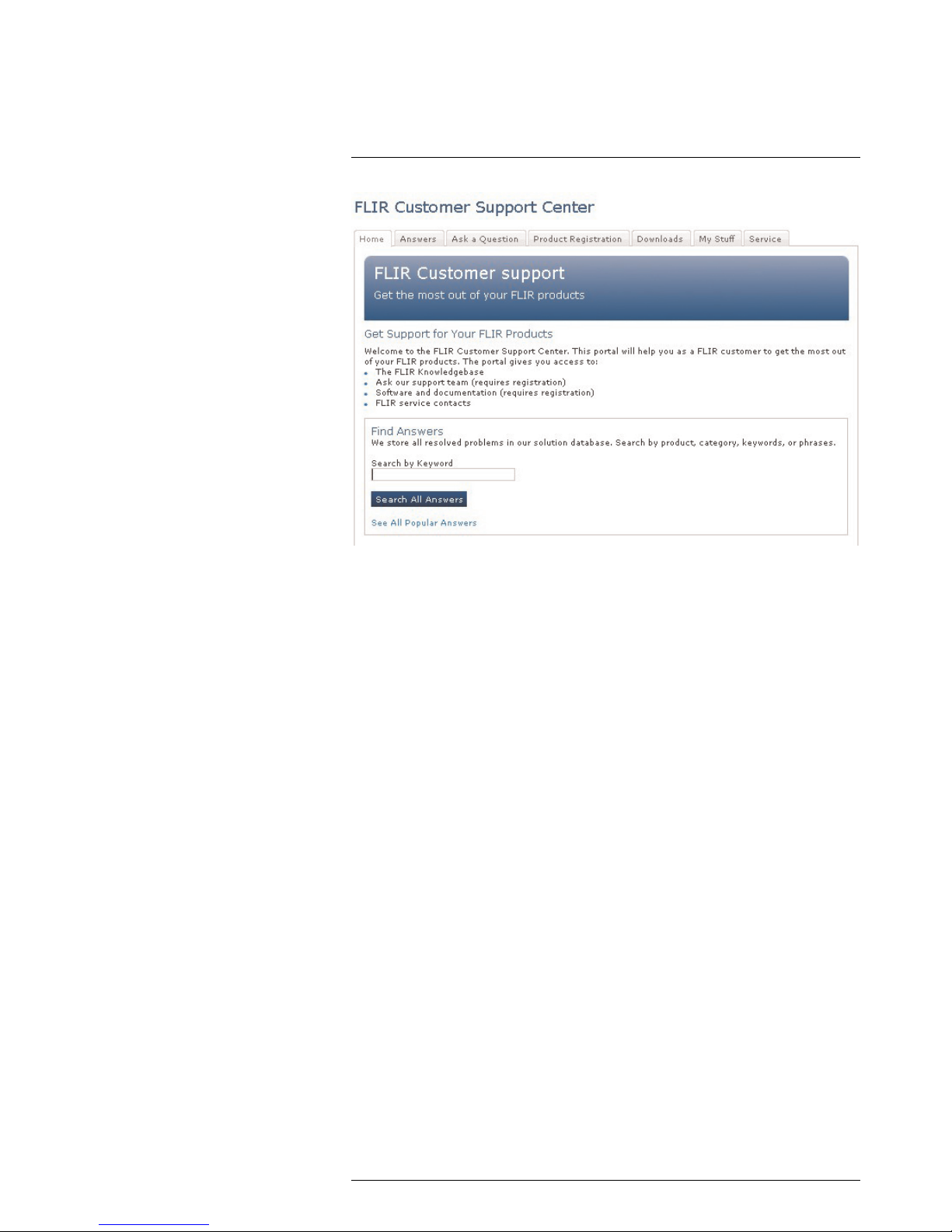
4.1 General
For customer help, visit:
http://support.flir.com
4.2 Submitting a question
To submit a question to the customer help team, you must be a registered user. It only
takes a few minutes to register online. If you only want to search the knowledgebase for
existing questions and answers, you do not need to be a registered user.
When you want to submit a question, make sure that you have the following information
to hand:
• The camera model
• The camera serial number
• The communication protocol, or method, between the camera and your device (for example, HDMI, Ethernet, USB, or FireWire)
• Device type (PC/Mac/iPhone/iPad/Android device, etc.)
• Version of any programs from FLIR Systems
• Full name, publication number, and revision number of the manual
4.3 Downloads
On the customer help site you can also download the following:
• Firmware updates for your infrared camera.
• Program updates for your PC/Mac software.
• Freeware and evaluation versions of PC/Mac software.
• User documentation for current, obsolete, and historical products.
• Mechanical drawings (in *.dxf and *.pdf format).
• Cad data models (in *.stp format).
• Application stories.
• Technical datasheets.
• Product catalogs.
#T559770; r. AB/ 9454/9454; en-US
8
Introduction
5
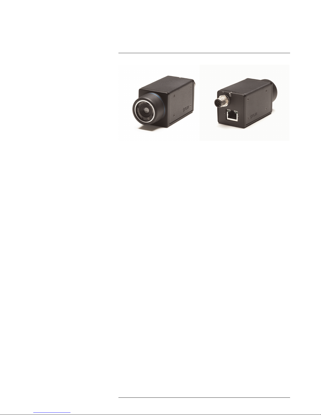
The FLIR Ax5 series cameras have features and functions that make them the natural
choice for anyone who uses PC software to solve problems. Available resolutions include
80 × 64, 160 × 128, and 320 × 256 pixels.
Among their main features are GigE Vision and GenICam compliance, which makes
them plug-and-play when used with software packages such as IMAQ Vision and Halcon.
Key features:
• Very affordable.
• Compact (40 × 43 × 106 mm/1.57 × 1.69 × 4.17 in.).
• GigE Vision and GenICam compliant.
• GigE Vision lockable connector.
• PoE (power over Ethernet).
• 8-bit monochrome image streaming.
• 14-bit radiometric image streaming.
• High frame rates (60 Hz).
• Synchronization between cameras possible.
• 1x+1x GPIO.
• Compliant with any software that supports GenICam, including National Instruments
IMAQ Vision, Stemmers Common Vision Blox, and COGNEX Vision Pro.
• Lenses: 5°, 9°, 13°, 19°, and 25° (model-dependent).
Typical applications:
• Automation, thermal machine vision.
• Entry-level “high-speed” R&D.
#T559770; r. AB/ 9454/9454; en-US
9

Parts lists
6
6.1 List of contents
• Infrared camera with lens
• Base support, incl. screws and Torx key*
• Cable tie (2 of)*
• Cardboard box*
• Downloads brochure
• Ethernet cable (2 of)*
• FLIR Tools download card*
• FLIR Tools+ scratchcard*
• FLIR apps card
• Focus adjustment tool*
• Getting started guide
• Gooseneck*
• Hard transport case*
• Important information guide
• Mains cable kit*
• Optics brochure
• PoE injector*
• Registration card
• Service and training brochure
• Table stand*
• Thank you card
• User documentation CD-ROM
* Dependent on the camera model.
Note
FLIR Systems reserves the right to discontinue models, parts or accessories, and other items, or to
change specifications at any time without prior notice.
6.2 Accessories
• T198349, Base support
• T198348, Cable kit mains (UK, EU, US)
• T127605, Cable M12 pigtail
• T127606, Cable M12 sync
• T198342, Focus adjustment tool
• T911112, PoE injector
• T198371, Transport case
• T198392, Table stand kit
Note
FLIR Systems reserves the right to discontinue models, parts or accessories, and other items, or to
change specifications at any time without prior notice.
#T559770; r. AB/ 9454/9454; en-US
10
Mechanical installation
7
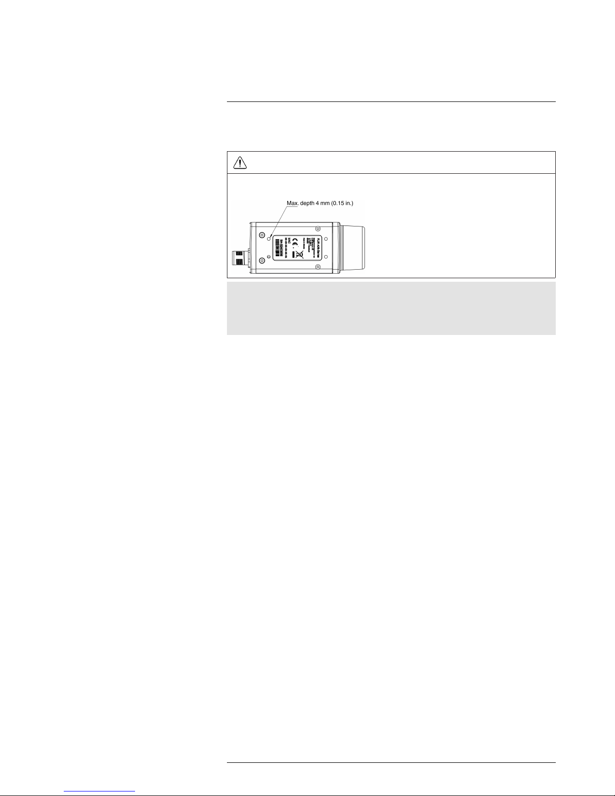
The camera unit has been designed to allow it to be mounted in any position. It has a
mounting interface on the bottom with four metric M3 holes.
WARNING
Do not use screws that are too long. Using screws that are too long will damage the camera. The maximum depth of the M3 holes is 4 mm (0.15 in.).
Note
The camera generates a considerable amount of heat during operation. This is normal. In order to
transfer this heat, it is recommended that the camera is mounted on a base support or a heat sink
made of a material that has a high capacity to transfer heat, e.g., aluminum. FLIR Systems provides P/
N T198349 (base support) for this purpose, but other base supports or heat sinks can be used.
If the camera unit is to be permanently mounted on the application site, certain steps
have to be taken. The camera unit might need to be enclosed in a protective housing
and, depending on the ambient conditions (e.g., temperature), the housing may need to
be cooled by means of water or air. In very dusty conditions the installation might also
need to have a stream of pressurized air directed at the lens, in order to prevent dust
build-up.
When mounting the camera unit in harsh environments, every precaution should be taken when it comes to securing the unit. If the environment exposes the unit to severe vibrations, there may arise a need to secure the mounting screws by means of Loctite or
another industrial brand of thread-locking liquid, as well as to dampen the vibrations by
mounting the camera unit on a specially designed mounting base.
For further information regarding mounting recommendations and environmental enclosures, contact FLIR Systems.
The camera is typically powered using PoE (Power over Ethernet). A PoE injector and
cable kit are available from FLIR Systems. See the part numbers below.
• T198348, Cable kit mains (UK, EU, US).
• T911112, PoE injector.
• T951004, Ethernet cable CAT-6, 2 m/6.6 ft.
#T559770; r. AB/ 9454/9454; en-US
11
Focusing the camera
8
8.1 Focusing cameras with 5, 9, 13, and 19 mm lenses
8.1.1 Necessary tools
Focus adjustment tool (included in the package for cameras with 5, 9, 13, and 19 mm
lenses).
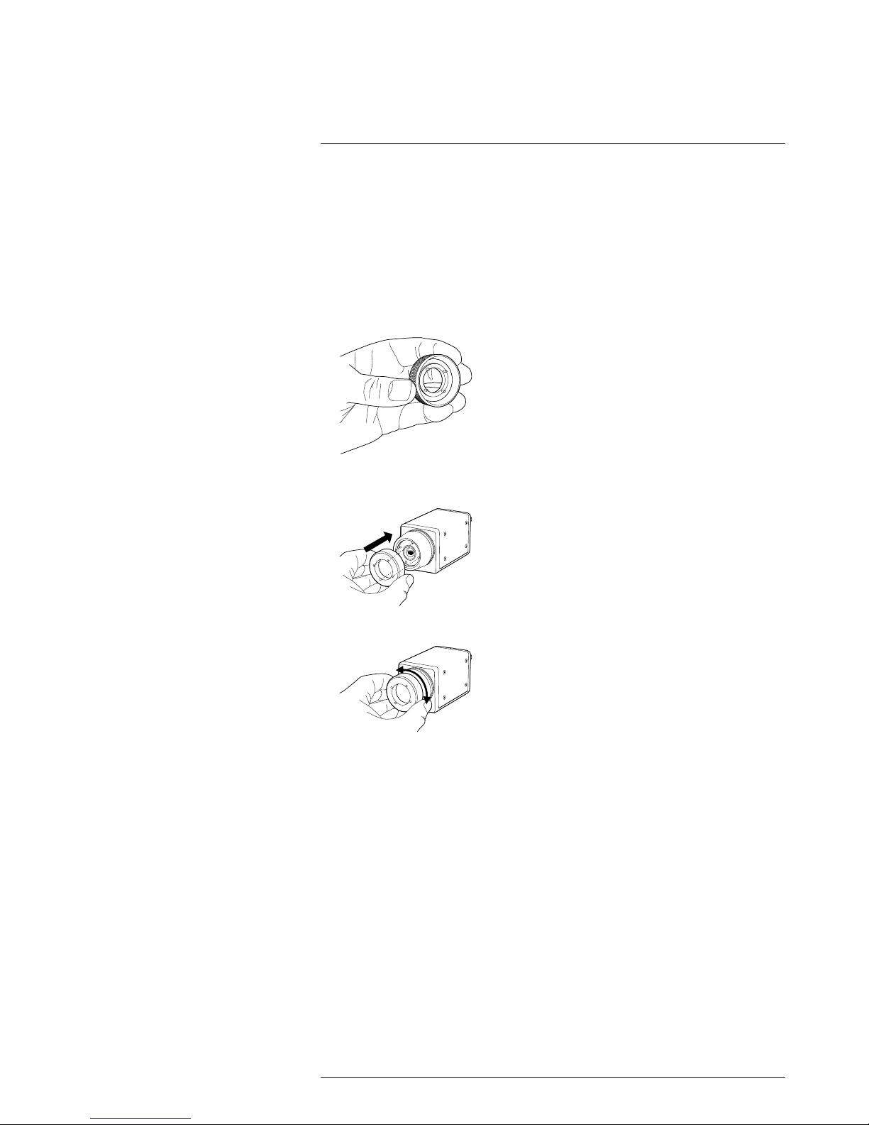
8.1.2 Procedure
Follow this procedure:
1. Note the four pegs on the inside of the focus adjustment tool.
2. Align the four pegs with the corresponding slots on the front of the lens, and push the
focus adjustment tool into position.
3. Rotate the lens.
#T559770; r. AB/ 9454/9454; en-US
12
Focusing the camera8
8.2 Focusing cameras with 25 mm lenses
CAUTION
Do not use the focus adjustment tool when focusing cameras with a 25 mm lens.
8.2.1 Necessary tools
Allen wrench, 1.5 mm.
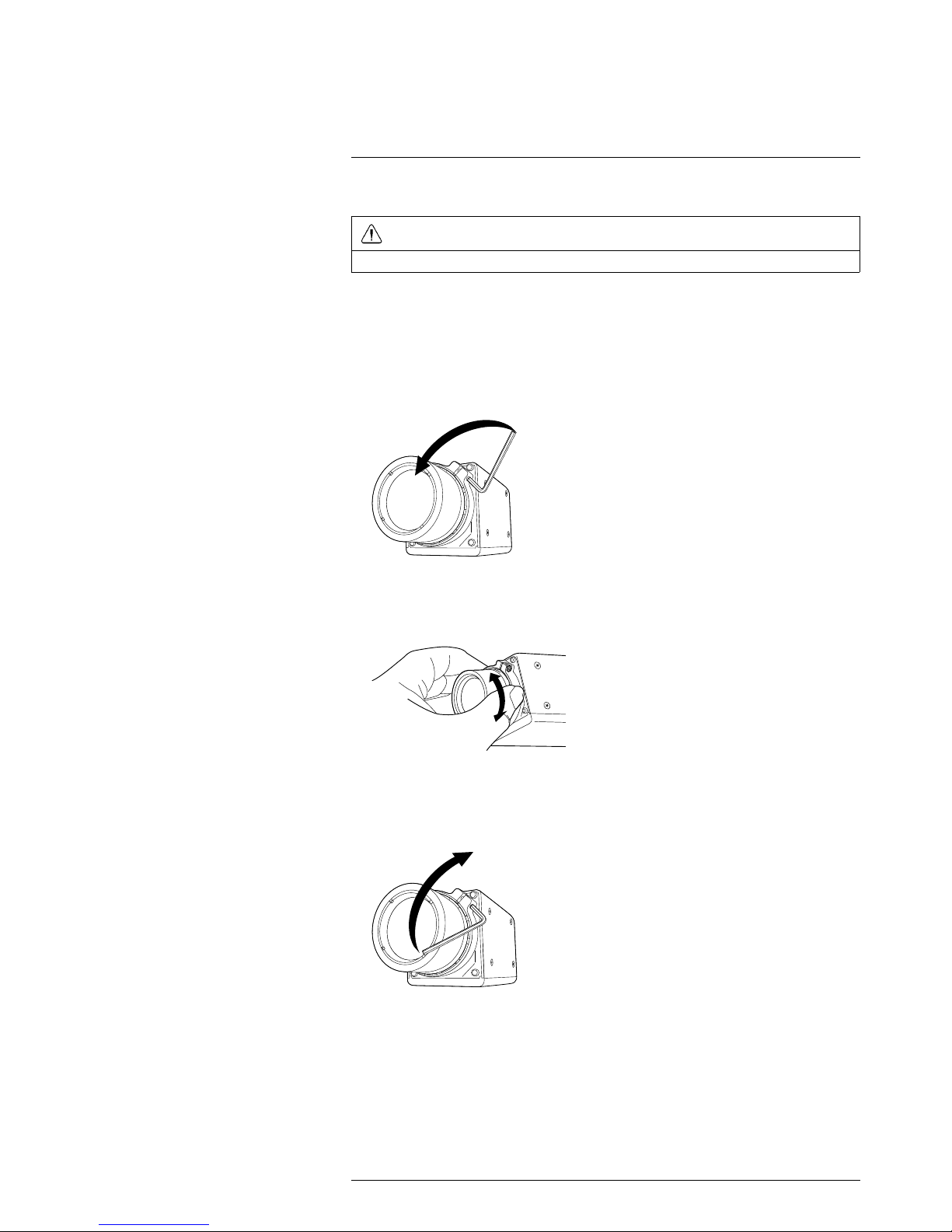
8.2.2 Procedure
Follow this procedure:
1. Unlock the clamp by loosening the Allen screw.
2. Focus the camera by rotating the lens.
3. Lock the clamp by tightening the Allen screw.
#T559770; r. AB/ 9454/9454; en-US
13

Downloads
9
The principal software used to configure and control the camera is FLIR GEV Demo
1.3.0. This software is based on the PleoraeBus SDK and the runtime Pleora GEVPlayer
that comes with the SDK.
Downloads:
• http://support.flir.com/Ax5-software
• Link to download PureGEV SDK Sample (source code): http://support.flir.com/
SwDownload/app/RssSWDownload.aspx?ID=133
• Link to download FLIR GEV Demo 1.3.0 (installer): http://support.flir.com/SwDownload/app/RssSWDownload.aspx?ID=155
The camera is compliant with the following standards. Additional software and documentation resources can be downloaded from these sites.
• GeniCAM: http:www.genicam.org
• Gigabit Ethernet: http://www.ieee802.org/3
#T559770; r. AB/ 9454/9454; en-US
14

About I/O, synchronization, and
measurement
10
10.1 FLIR Ax5 series General Purpose I/O
The FLIR Ax5 series camera has one general-purpose input line and one output line that
can be used in control applications.
Typical usage:
• The output line is asserted when an alarm condition is met.
• The input line is used to trigger an action, for example saving an image.
The output line GPO+ is controlled by the register UserOutputValue. Set this register to
True to assert (level equal to GPIO_PWR) the GPO+ signal, and set to False to de-assert
(level is equal to GPIO_GND).
You can monitor the input line by reading the LineStatus register on a regular basis. The
LineStatus register will returnTrue if the input level is asserted (level equal to GPIO_PWR
voltage), and it will returnFalse if the input line is de-asserted (level is equal to GPIO_
GND).
Another option is to configure the camera to send a GigEVision event when the input line
state is changed. In order to configure the camera for event transmission you need to
modify the following registers:
PLC_Q7_Variable0
Enum
Set this register to PLC_I0 (enumeration value 2) to route the
GPI signal
EventSelector
Enum
Set this register to PLC_Interrupt_FIFO0_Q7 (enumeration
value 5)
EventNotification Enum Set this register to GigEVisionE-
vent (enumeration value 3)
To de-bounce the input signal you also might want to configure the LineDebounceFactor
register. This register controls the width of the window during which spurious transitions
from the input line are filtered out (in increments of ~480 ns). This register is 0 by default,
which means that the de-bouncing is disabled. The maximum value for this register is
65535, which corresponds to a maximum holding time of ~31 ms.
The FLIR GEV Demo 1.3 sample illustrates how to setup the event transmission. C++
source code is available in PureGEV SDK Sample.
Applicable downloads:
• Link to download PureGEV SDK Sample (source code): http://support.flir.com/
SwDownload/app/RssSWDownload.aspx?ID=133
• Link to download FLIR GEV Demo 1.3.0 (installer): http://support.flir.com/SwDownload/app/RssSWDownload.aspx?ID=155
10.2 FLIR Ax5 series synchronization
The camera provides an external sync channel that can be used to synchronize the
frame start between two cameras, one configured as the master and the other configured as the slave. It can also be used to synchronize the frame start of a camera with that
of another product.
#T559770; r. AB/ 9454/9454; en-US
15
 Loading...