

Page 1
ARMASIGHT by FLIR
Night Vision Binoculars
®
BNVD
USER MANUAL
Page 2

© 2017 FLIR Systems, Inc. All rights reserved worldwide. No parts
of this manual, in whole or in part, may be copied, photocopied,
translated, or transmitted by any electronic medium or in
machine-readable form without the prior written permission of
FLIR Systems, Inc.
Names and marks appearing on the products herein are either
registered trademarks or trademarks of FLIR Outdoor & Tactical
Systems and/or its subsidiaries. All other trademarks, trade names, or
company names referenced herein are used for identification only and
are the property of their respective owners.
This product is protected by patents, design patents, patents pending,
or design patents pending.
If you have questions that are not covered in this manual, or need
service, contact FLIR OTS customer support for additional information
prior to returning a camera.
Phone:1-888-959-2259
E-mail: OTS-Support@flir.com
This documentation is subject to change without notice.
Proper Disposal of Electrical
and Electronic Equipment (EEE)
The European Union (EU) has enacted Waste Electrical
and Electronic Equipment Directive 2002/96/EC (WEEE),
which aims to prevent EEE waste from arising; to
encourage reuse, recycling, and recovery of EEE waste;
and to promote environmental responsibility.
In accordance with these regulations, all EEE products labeled with the
“crossed out wheeled bin” either on the product itself or in the product
literature must not be disposed of in regular rubbish bins, mixed with
regular household or other commercial waste, or by other regular
municipal waste collection means. Instead, and in order to prevent
possible harm to the environment or human health, all EEE products
(including any cables that came with the product) should be responsibly
discarded or recycled.
To identify a responsible disposal method where you live, please
contact your local waste collection or recycling service, your original
place of purchase or product supplier, or the responsible government
authority in your area.
Business users should contact their supplier or refer to their purchase
contract.
Important Instructions and Notices
to the User:
Modification of this device without the express authorization of FLIR
Commercial Systems, Inc. may void the user’s authority under FCC rules
to operate this device.
Note 1: This equipment has been tested and found to comply with the
limits for a Class B digital device, pursuant to Part 15 of the FCC rules.
These limits are designed to provide reasonable protection against
harmful interference in a residential installation.
This equipment generates, uses, and can radiate radio
frequency energy and, if not installed and used in accordance
with the instructions, may cause harmful interference to radio
communications. However, there is no guarantee that the interference
will not occur in a particular installation. If this equipment does
cause harmful interference to radio or television reception, which
can be determined by turning the equipment off and on, the user is
encouraged to try to correct the interference by one or more of the
following measures:
• Reorient or relocate the receiving antenna
• Increase the separation between the equipment and receiver
• Connect the equipment into an outlet on a circuit different from
that of the receiver
• Consult the dealer or an experienced radio/television
technician for help.
Industry Canada Notice:
This Class B digital apparatus complies with
Canadian ICES-003.
Avis d’Industrie Canada:
Cet appareil numérique de la classe B est conforme à la norme
NMB-003 du Canada.
FLIR Outdoor & Tactical Systems
815 Dubuque Avenue, South San Francisco, CA 94080
Phone: 1-888-959-2259 or (650) 492-7755
Fax: 1-888-959-2260
International Phone/Fax: (650) 492-7755
E-mail: OTS-Support@flir.com
www.flir.com
Export Information
Equipment described herein may require US Government authorization
for export purposes. Diversion contrary to US law is prohibited.
©2017 FLIR Systems, Inc. Specifications are subject to change
without notice, check our website: www.flir.com.
2
ARMASIGHT by FLIR
BNVD
USER MANUAL
Page 3

CONTENT
Page
Safety Statement 4
1. Introduction 5
2. Getting Started 6
3. Operating the System 8
4. Maintenance 12
5. Warranty 13
6. Specifications 14
7. Spare Parts 15
ARMASIGHT by FLIR
BNVD
USER MANUAL
3
Page 4

SAFETY STATEMENT
WARNING:
The image intensifier’s phosphor screen contains toxic materials.
• If an image intensifier is broken, be extremely careful to avoid
inhaling the phosphor screen material. Do not allow the material to
come in contact with the mouth or open wounds on the skin.
• If the phosphor screen material contacts your skin, wash it off
immediately with soap and water.
• If you inhale/swallow any phosphor screen material, drink a lot
of water, induce vomiting, and seek medical attention as soon as
possible.
WARNING:
This product contains natural rubber latex, which may cause
allergic reactions! The FDA has reported an increase in the number
of deaths that are associated with an apparent sensitivity to natural
latex proteins. If you are allergic to latex, it is a good idea to learn
which products contain it and strictly avoid exposure to those products.
Important Safety Instructions
• Read and follow all instructions
• Heed all warnings
CAUTION:
• The BNVD is a precision optical instrument. To prevent damage to
the unit, it should always be handled carefully.
• Do not scratch the external lens surfaces or touch them with your
fingers.
• To protect the image intensifier, keep the lens cap securely fitted
over the objective lens when the device is not in use, or when it is
being used in daylight conditions.
• Keep the equipment clean. Protect it from moisture, dramatic
temperature drops, and electrical shocks.
• DO NOT force the equipment controls past their stopping points.
• DO NOT leave the equipment activated during breaks in operation.
• DO NOT store the equipment with the batteries installed.
• Thoroughly clean and dry each item before placing them into the
storage case.
NOTES:
• Do not test the device in daylight conditions for more than ten (10)
minutes, even with the daylight filter/ lens cap on.
• The purpose of the built-in IR illuminator is to provide additional
illumination when necessary while viewing scenes at close distances
(up to 3 meters).
• Only use the attachments/accessories specified by the manufacturer
• All service must be provided by the manufacturer
WARNING:
• DO NOT DISASSEMBLE THE DEVICE.
Disassembly can cause permanent damage.
• Use of the BNVD in brightly light conditions and in the places with
bright light sources such as firelight, headlights, searchlights, etc.
can damage the unit’s intensifier tubes. Avoid exposing the unit to
these types of light sources.
• When operating the device in extremely dark conditions, the light
from the unit’s IR illuminator will be invisible to the unaided eye.
However, the light can be detected by other night vision devices
(NVD).
• To reduce the risk of detection by another NVD, avoid prolonged
activation of the IR illuminator.
• The IR light is more easily detected by an NVD when used in smoke,
fog and rain. Avoid prolonged activation of the unit’s IR illuminator in
these conditions.
• The equipment requires some ambient light (moonlight, starlight,
etc.) to operate.
• Performance of the device in nighttime conditions depends on the
level of ambient light in the environment. Please remember the
following:
- The level of ambient light is reduced by the presence of clouds,
shade, or objects that block natural light (trees, buildings, etc.).
- The equipment is less effective when operated in shadows and
other darkened areas.
- The equipment is less effective when operated in rain, fog, sleet,
snow, dust or smoke.
- The equipment will not “see” through dense smoke.
BNVD® Night Vision Binoculars
The BNVD® is used as a night vision goggles or a handheld night vision
binoculars. Nevertheless, in the industry, and throughout this manual,
this type of device is also referred to as NVG.
4
ARMASIGHT by FLIR
BNVD
USER MANUAL
Page 5
SECTION 1. INTRODUCTION
1.1 BINOCULARS
This manual covers the BNVD night vision binoculars and all applicable
components. It is recommended that you read and understand this
manual to optimize the binoculars operation.
1.2 INTRODUCTION
The BNVD is a hand-held, head-mounted or helmet-mounted night
vision system that enables mobility, driving, weapon firing, short-range
surveillance, map reading, vehicle maintenance and administering first
aid during operation in both moonlight and starlight.
The BNVD is a dual-channel night vision device. The BNVD uses
advanced, multi-coated optics and a tough, compact, and ergonomic
composite housing. The BNVD can be used as a monocular or binocular
goggles, or stowed out of the way without removing. Rotating binocular
design allows low profile against helmet when in stowed position. This
device operates with a single gain control knob and utilizes features
like a flip up turn off with flip down turn back on function, when used
in conjunction with a compatible head/ helmet mount. There is also an
integral infrared illuminator for reading a map.
1.3 FEATURES
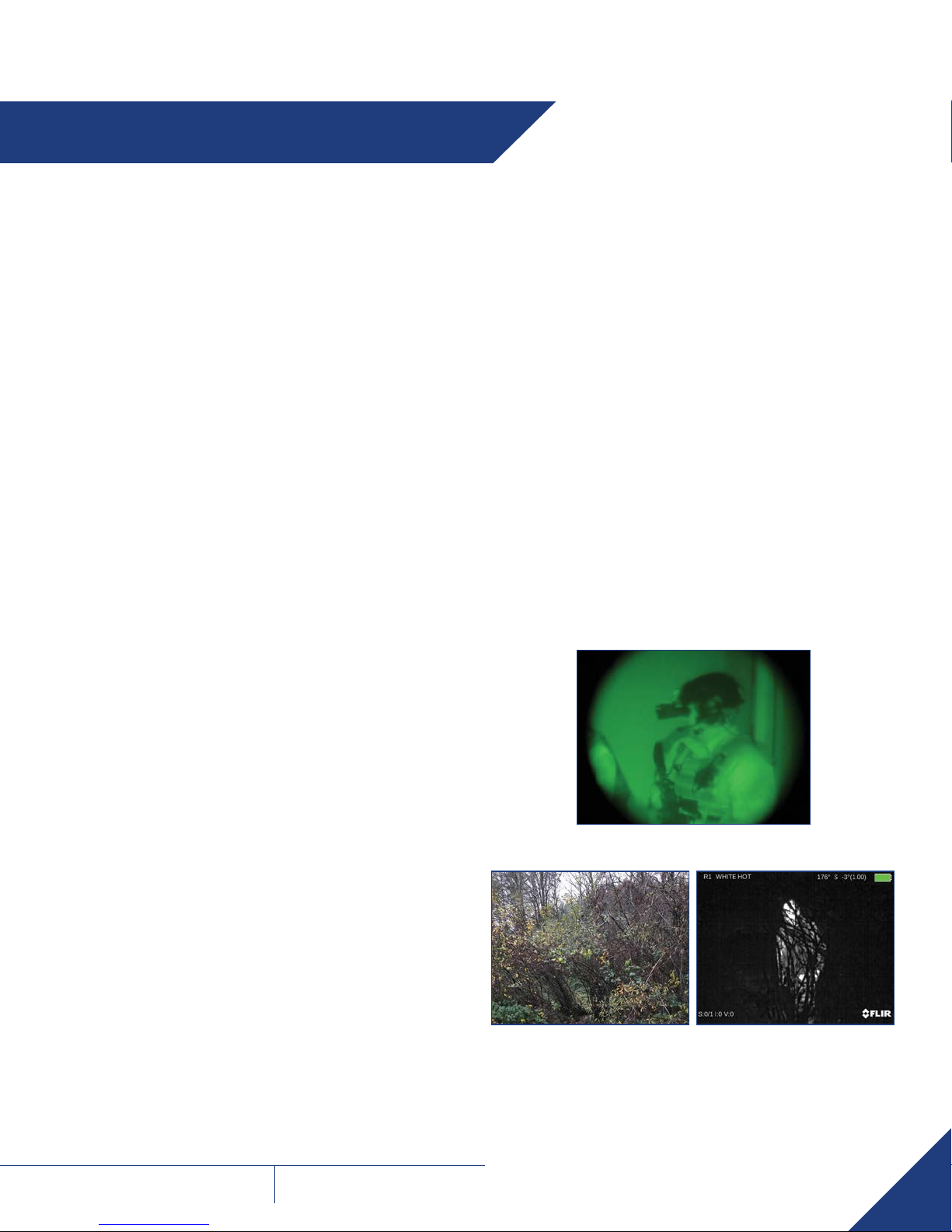
1.5 IMAGE INTENSIFIED NIGHT VISION
VERSUS INFRARED THERMAL VISION
Image Intensification “I2” works by collecting tiny amounts of light,
including the lower portion of the infrared light spectrum, that are
present but may be imperceptible to our eyes, and amplifying it to the
point that we can easily observe the image.
Thermal imagingtechnology operates by capturing the upper portion of
the infrared light spectrum, which is emitted as heat by objects instead
of simply reflected as light. Hotter objects, such as warm bodies, emit
more of this light than cooler objects, like trees or buildings.
The thermal vision device makes images from heat, not light, a feat
impossible for the naked eye or image intensified (I
devices. This allows you to see clearly without any visible light. People,
animals, and objects all generate or reflect heat, and are clearly seen
by the thermal vision device, in even the most adverse conditions.
Thermal is best used to detect the desired object. It is the best 24-hour
imaging option.
Night vision devices provide a more natural image, wider field of view
(FOV), wider operating temperature, and longer battery life.
2
) night vision
• Rotating binocular design allows low profile against helmet when in
stowed position and ability to use as a single monocular
• Binocular design for sustained viewing periods and improved depth
perception
• Manual system gain and focus adjustments for custom image quality
optimization
• Auto OFF when stowed; resumes power when deployed
• Integrated infrared (IR) illuminator
• Head or helmet-mountable
• Low-battery, bright light cut-off, and IR indicators in eyepiece
• Self-contained system operating on a single AA or CR123 battery
• Compact and lightweight, rugged construction
• Optional remote battery pack for extended use
• Limited 2-year warranty
1.4 REGISTER YOUR BNVD
You can register your product online at:
www.flir.com
I2 IMAGE IN NEAR TOTAL DARKNESS
THERMAL IMAGING
ARMASIGHT by FLIR
BNVD
USER MANUAL
5
Page 6

SECTION 2. GETTING STARTED
2.1 UNPACKING AND INSPECTING
The BNVD is available with the features, options, and accessories
described in this manual. Refer to the packing list enclosed with your
product to determine the actual contents of your product package.
Mounting Bracket
(preinstalled NVG
Interface Shoe)
Lens Cap
Eyecup
CR123 Lithium
Battery
2.2 BAT TERY
The BNVD operates on a single CR123A or AA battery. This is possible
by repositioning the battery adapter in the battery cap.
LOW BATTERY INDICATOR
When the binoculars are ON, a flashing red LED indicator in the
eyepiece viewing area indicates that the battery is low. This indicator
provides an alert the user to replace the battery.
CR123A BATTERY INSTALLATION
1. Unscrew the battery cap and insert the CR123A battery, observing
the polarity markings on the body of the device.
2. With the battery adapter installed, screw the battery cap back on
securely.
Battery Polarity Symbol
Battery
Cap
CR123A Battery
Battery
Adapter
Soft Carrying
Case
Lens Cloth
Sacrificial Window
Quick Start Guide Thank You Card
Bayonet/Horn
Interface Shoe
Demist Shield
AA BATTERY INSTALLATION
1. Unscrew the battery cap.
2. Unscrew the battery adapter from the cap, turn it around, and screw
in the other end.
3. Insert the AA battery, observing the polarity markings as indicated on
the body of the device.
4. Screw the battery cap back into place.
Battery Polarity Symbol
Battery
Cap
Battery
Adapter
AA Battery
6
ARMASIGHT by FLIR
BNVD
USER MANUAL
Page 7

2.3 OPTIONAL EQUIPMENT
Optional items are shown and listed in the table below. The PART NO. column indicates the primary number used by the manufacturer to identify an
item.
IMAGE DESCRIPTION PART NO.
3x Afocal Lens Kit for BNVD
(Includes: two 3x Afocal Lenses with two adapters #215)
Battery Pack #206
(Includes: Battery Pack Bracket #231, Nylon Bag)
Battery Pack Kit
(Includes: Battery Pack #206 w/ Battery Pack Bracket #231 and Nylon Bag, NVG Interface Shoe
with Connector #212, Battery Locking Plate Adapter #213)
Battery Locking Plate Adapter #213 ANAM000213
NVG Interface Shoe with Connector #212 ANAM000212
Goggle Kit for BNVD
(Includes: Goggle Kit #205, Adapter #224)
ANAF3X0215
ATAM000206
ATAMNYX15M
ANHGNYX205
Tactical Goggle Kit for BNVD
(Includes: Wilcox L4 G24 w/ Low Profile Breakaway mount, Wilcox 3 Hole Shroud, Wilcox
Lanyard, Crye Precision Head Cap)
Helmet Mount Kit for BNVD
(Includes: Helmet Mount #3, Adapter #224)
Hard Shipping/ Storage Case #101 ANHC000001
ARMASIGHT by FLIR
BNVD
USER MANUAL
ANHGWXNYX0
ANHMNYX15M
7
Page 8

SECTION 3. OPERATING THE SYSTEM
3.1 SYSTEM DESCRIPTION
The BNVD utilizes the principle of intensification of the residual light
that is reflected from the surrounding objects. The optical system of the
unit consists of two monocular channels, each consisting of a lens, an
image intensifier tube (IIT), and an eyepiece.
This device operates with a single gain control knob for both channels.
Each unit allows for vertical adjustment (using the head or helmet
mount), fore-and-aft adjustment, objective lens focus, eyepiece focus,
and interpupillary distance adjustment. The binoculars are equipped
with an infrared (IR) light-emitting diode (or illuminator) to provide
additional illumination for reading a map. The binoculars are also
equipped a low battery indicator, a bright light cut-off system indicator,
and IR illuminator indicator in the field of view of device.
Built-In IR
Illuminator
Interpupillary
Distance
Adjustment
Knob
Gain Control
Knob
Focus
Ring
Turn-Pull
Operating Switch
Mounting
Bracket
Diopter
Adjustment Ring
Eyepiece
3.2.2 DIOPTER ADJUSTMENT RING
The diopter adjustment ring allows a user to alter the viewfinder to
accommodate that individual’s eyesight for optimum image sharpness.
While looking through the eyepiece, rotate the diopter adjustment ring
to optimize the sharpness of the image in the viewfinder.
3.2.3 FOCUS RING
Bring the object into focus by turning the objective focus ring (counter
clockwise for far focus, clockwise for near focus, if you look in the
eyepieces). Rotate the focus ring until the subject looks sharp in the
viewfinder.
3.2.4 INTERPUPILLARY DISTANCE KNOB
ADJUSTMENT
Adjusts the distance between each eyepiece by rotating the knobs
together or apart, allowing for each eye to observe the entire field at
the same time.
3.2.5 GAIN CONTROL KNOB
Used to adjust the gain (brightness) of the viewed image. Turn the gain
control to balance the illumination input to the eyes.
3.2.6 INDICATION
Battery Cap
Photoreceiver
of Bright Light
Cutoff System
Focus Ring
Interpupillary Distance
Adjustment Knob
3.2 SYSTEM CONTROLS
3.2.1 TURN-PULL OPERATING SWITCH
The turn-pull operating switch performs the following functions:
• Activates the BNVD when turned to ON.
• To activate built-in IR illuminator, pull switch out and turn to IR
position. The IR illuminator will activate on, and red LED indicators
in both eyepieces will glow. Rotate the switch to ON position to
deactivate the IR.
• Deactivates the BNVD when turned to OFF position.
When the BNVD is ON, the color LED indicators can be shown in the
field of view. The color LEDs indicate the following states of the device:
INDICATIONS
COLOR OF LED
IN THE FOV
Built-in IR illuminator is activated Red
Image intensifier tubes are exposed to
excessive levels of light
Green
Battery is low Flashing Red
3.3 AUTO POWER OFF FUNCTION
The BNVD bright light cut-off feature shuts off power to the binoculars
when they are exposed to excessive levels of light for more than 10
seconds.
Automatic shut-off system automatically turns off the device when it is
unused (controls are not touched) for 60 minutes. The automatic shutoff function preserves battery life should the device be inadvertently
activated.
8
ARMASIGHT by FLIR
BNVD
USER MANUAL
Page 9

3.4 OPERATING PROCEDURES
1. Verify that the battery is installed as indicated on the unit body.
2. Remove the lens cap and place it over the housing of the lens.
3. Turn the function switch ON. After a slight delay, a green glow will
appear in the eyepiece of the unit.
4. Adjust the unit diopter by rotating the ring of the eyepiece.
5. Observe the scene. Rotate the focus ring until the image is clear and
sharp.
6. Adjust the brightness of the image using the gain control knob.
The BNVD can be used as one-eye observational unit by choosing
which side you want to use as your night vision monocular and rotate
the other unit up and out of the way. The power of unit will be switched
off in rotated up position and it will be on automatically when returned
back to the working position.
3.5 IR ILLUMINATOR OPERATIONS
NOTE:
The built-in IR illuminator is designed to provide additional
illumination (when needed) while viewing scenes or targets from
a short distance (up to 3m).
To turn built-in IR Illuminator on, pull the operation switch out and turn
it from ON to the IR position.
Red LED indicators in field of view of both eyepieces will appear and
indicate the IR illuminator is operating.
Rotate the switch to ON position to deactivate the IR.
IR Illuminator will be switched off when both monocular units are
rotated to the side and upward. IR Illuminator will be on automatically
when one of monoculars returns to the working position.
3.6 OPERATING UNDER CHANGING LIGHT
CONDITIONS
If the ambient light level exceeds the limit, the BNVD automatic
protective system will shut off the intensifier tubes. If a mission must
be carried out in changing light conditions, the user can shut down the
protective system manually by closing the photoreceiver.
Monocular Goggles Position
Stowed Position
NOTE:
If the automatic shut-off system turns off the device, turn the
operation switch to OFF position and then back to ON position
for continuing operation.
CAUTION:
DO NOT forget to open the photoreceiver after completing your
mission.
3.7 INSTALLING A MOUNTING BRACKET TO
THE BNVD
The BNVD comes fully-assembled with a dovetail type NVG Interface
Shoe. The NVG Interface Shoe is attached to the binoculars body with
four flathead socket cap screws.
Bracket Fixing Screws
Mounting Bracket
(preinstalled NVG
Interface Shoe)
NOTE:
If the bright light cut-off feature turns off the device, the power
will turn on automatically when the level of light decreases.
ARMASIGHT by FLIR
BNVD
USER MANUAL
9
Page 10

To replace the NVG Interface Shoe to other optional bracket, please
follow the instructions below:
1. Remove the four screws that attach the bracket to the unit body.
2. Remove the bracket.
3. Place a new bracket and affix with four screws.
3.8 MOUNTING THE BNVD TO A
HELME T/ HEADGEAR ASSEMBLY
For hands-free use of the BNVD, it can be installed to the AN/PVS-7D,
AN/PVS-14, AN/PVS-7A/C, AN/PVS-15, and AN/PVS-18 mounts, or to
the mounts with mini-rail interface. With the mount, the BNVD can be
positioned directly in front of the user’s eyes, or flipped out of the field
of view.
NVG Interface Shoe (preinstalled) is used for installing the BNVD to
either standard dovetail type headset and helmet mounts.
Dovetail Type
Helmet Mount
NVG Interface Shoe with Connector is used for installing the BNVD
to either standard dovetail type headset and helmet mounts and
connecting the Battery Pack.
NVG Interface
Shoe with
Connector
Adapter #224 (Mini-Rail Interface Shoe) is used for installing the BNVD
to the Goggle Kit #205 and Helmet Mount #3 with mini-rail interface.
NOTE:
The power of BNVD will be turned off when the device is swing
up using the flip-up mechanism of Goggle Kit #205 or Helmet
Mount #3. The power will be on automatically when device is
returned back to the working position.
Bayonet/Horn Interface Shoe is used for installing the BNVD to either
standard bayonet/horn type headset and helmet mounts.
Bayonet/Horn
Type Helmet
Mount
Bayonet/Horn
Interface Shoe
Mini-Rail
Interface Shoe
Install the necessary bracket to the BNVD per instructions in paragraph
3.7.
Mount the BNVD to helmet/ headgear assembly. Put on the helmet/
headgear assembly and adjust the position of binoculars regarding your
eye.
10
ARMASIGHT by FLIR
BNVD
USER MANUAL
Page 11

3.9 USING A BATTERY PACK
The BNVD with installed NVG Interface Shoe with Connector can be
used in conjunction with the Battery Pack for longer run times. When
the Battery Pack is connected, it works in conjunction with an internal
power source.
When BNVD is used as goggle system, the Battery Pack can be
installed with Battery Pack Bracket #231 or Nylon Bag on the back side
of the helmet.
The Battery Pack connects to the NVG Interface Shoe using the Lemo
connector on the cable.
Connector
NVG Interface
Shoe with
Connector
Battery Pack
Cable
To mount the afocal lens, be slip over the end of the objective lens of
BNVD. Carefully push the afocal lens until it stops.
3x Afocal Lens
3.11 DEMIST SHIELD INSTALLATION
Mount a Demist Shield to the BNVD as follows:
1. Remove the eyecup from the BNVD eyepiece.
2. Coat the Demist Shield with an anti-fogging compound, to prevent
moisture condensation on the surface of the shield.
3. Screw the Demist Shield into the threading of the eyepiece.
4. Secure the eyecup back into place.
Battery Pack Bracket
When BNVD is used as hand-held NV binoculars, the Battery Pack can
be installed with the Battery Locking Plate Adapter directly to the NVG
Interface Shoe with Connector.
Battery Pack
Connector
3.10 USING THE OPTIONAL AFOCAL 3X
LENS
The binoculars can be used as excellent long-range viewer with an
optional 3x afocal lens.
3.12 SACRIFICIAL WINDOW INSTALLATION
Mount a Sacrificial Window to the BNVD as follows:
1. Remove the BNVD lens cap, if it is in place.
2. Carefully push the Sacrificial Window onto the end of the objective
lens of BNVD until it stops.
ARMASIGHT by FLIR
BNVD
USER MANUAL
11
Page 12

SECTION 4. MAINTENANCE
4.1 BATTERY REMOVAL AND
REPLACEMENT
Refer to Part 2.2 for battery installation procedures.
4.2 CLEANING THE BNVD
Wipe the housing with a damp cloth as needed.
CAUTION: Do not use abrasives or solvents to clean the housing, lens,
or display window. Do not use ammonia-based cleaning products to
clean the lens. Doing so may damage the anti-reflective coating of the
lens.
The BNVD lens is designed for the harsh outdoor environment and has
a coating for durability and anti-reflection, but it may require cleaning
occasionally. Avoid scratching the lens and/or leaving fingerprints on
the optics. Optics can be damaged by improper cleaning. Clean the lens
according to the instructions below when image quality degradation is
noticed or excessive dirt or other contaminant is on the lens.
Do not use abrasive materials, such as paper or scrub brushes as this
will possibly damage the lens by scratching it. Only wipe the lens clean
when there is visible contamination on the surface.
PREFERRED METHOD FOR CLEANING THE LENS
Materials:
• Optical-grade cloth
• Pure water (de-ionized or other)
• Isopropyl alcohol (IPA)
Saturate a piece of the lens tissue with the water and drape it over
the lens. Let the surface tension of the water pull the tissue onto the
lens surface and then drag the tissue across the lens surface. Repeat
several times with different pieces of tissue.
Repeat the same step using IPA instead of water. Drag the final piece
of tissue over the lens several times to prevent pooling, which could
leave a residue behind.
12
ARMASIGHT by FLIR
BNVD
USER MANUAL
Page 13

SECTION 5. WARRANTY
5.1 GLOBAL LIMITED WARRANTY
Follow the link http://www.flir.com/uploadedFiles/Corporate/Support/
FLIR-Personal-Vision-Systems-2-3-10-Limited-Warranty.pdf to retrieve
FLIR’s Warranty document.
5.2 PRODUCT REGISTRATION
In order to validate the warranty on your product, FLIR Outdoor
& Tactical Systems must receive a completed Product Warranty
Registration Card for each unit, or the customer can complete
the warranty registration form on our website by completing and
submitting FLIR Outdoor & Tactical Systems’ PRODUCT REGISTRATION
FORM (http://www.flir.com/hunting-outdoor/display/?id=74583).
5.3 OBTAINING WARRANTY SERVICE
For service, repair or replacement, please contact:
FLIR Outdoor & Tactical Systems
815 Dubuque Avenue, South San Francisco, CA 94080
Phone: 1-888-959-2259 or (650) 492-7755
Fax: 1-888-959-2260
International Phone/Fax: (650) 492-7755
E-mail: OTS-Support@flir.com
www.flir.com/ots
ARMASIGHT by FLIR
BNVD
USER MANUAL
13
Page 14

SECTION 6. SPECIFICATIONS
BNVD-51 BNVD-40
OPTICAL SPECIFICATIONS
Magnication 1X
Lens System 19 mm; F/1.26 27 mm; F/1.3
FOV 51° 40°
Focus Range 0.25 m to Infinity
Eye Relief 17 mm 25 mm
USER INTERFACE
Operation Switch Power On/ Off; IR illuminator On/Off
Gain Control Knob Adjusts the image brightness
Diopter Adjustment Rings Adjusts the eyepiece diopter
Focus Rings Adjusts the objective lens focus
LED Indicators Indicates low battery, IR On, and excessive light conditions
SYSTEM SPECIFICATIONS
Manual Gain Control Yes
Bright Light Cut-Off Yes
Automatic Shut-Off System Yes
Low Battery Indicator Yes
IR Indicator Yes
Bright Light Cutoff System Indicator Yes
Infrared Illuminator Yes
POWER
Battery Type Single AA 1.5V battery or CR123A Lithium 3V battery / Optional Battery Pack
Battery Life (Operating) Up to 20 hrs;
up to 80 hrs with optional Battery Pack
ENVIRONMENTAL
Operating Temperature Range -40°C to +50°C (-40°F to +122°F)
Storage Temperature Range -50°C to +50°C (-58°F to +122°F)
PHYSICAL
Diopter Adjustment -6 to +2 dpt
Interpupilary Distance 54 to 78 mm
Weight 615 g (1.35 lb) 645 g (1.42 lb)
Size 115 × 118 × 73 mm (4.5 × 4.6 × 2.8”) 113 × 118 × 73 mm (4.4 × 4.6 × 2.8”)
PACKAGE INCLUDES
Night Vision Binoculars, NVG Interface Shoe (preinstalled), Bayonet/Horn interface Shoe, Demist Shield (2), Sacricial Window (2), Battery,
Lens Cloth, Quick Start Guide, Soft Carrying Case
14
ARMASIGHT by FLIR
BNVD
USER MANUAL
Page 15

SECTION 7. SPARE PARTS
The parts authorized in the below list of spare parts are required for
operator maintenance. This list includes parts that must be removed in
order to replace authorized parts.
The ITEM NO. column indicates the number used to identify items in
figure below.
The PART NO. column indicates the primary number used by the
manufacturer to identify an item; this number controls the design and
characteristics of the item by means of its engineering, specifications,
standards, and inspection requirements.
4 5
3
2
1
13
9
10/1112
6
7/8
ITEM NO. DESCRIPTION PART NO.
1 Lens Cap BNVDLNCP
2 Gain Control Knob BNVDGCK
3 Operating Switch BNVDOPSW
4 NVG Interface Shoe BNVDNVGIS
5 Bracket Fixing Screws BNVDBFS
6 Eyecup BNVDEYCP
7 BNVD-51 Eyepiece Assembly BNVD51EA
8 BNVD-40 Eyepiece Assembly BNVD40EA
Interpupillary Distance Adjustment
9
Knob
BNVDIDAK
10 BNVD-51 Objective Lens Assembly BNVD51OLA
11 BNVD-40 Objective Lens Assembly BNVD40OLA
12 Battery Cap BNVDBTCP
13 Battery Cap Retainer BNVDBCR
14 CR123A Lithium Battery ALT
14 15 16 17/18 19/20
24
21 22 23
15 AA Alkaline Battery ALT
16 Battery Adapter BNVDBTAD
17 Demist Shield for BNVD-51 BNVD51DS
18 Demist Shield for BNVD-40 BNVD40DS
19 Sacrificial Window for BNVD-51 BNVD51SW
20 Sacrificial Window for BNVD-40 BNVD40SW
21 Bayonet/Horn Interface Shoe BNVDBHIS
22 Lens Cloth BNVDLNCL
23 Soft Carrying Case BNVDSCC
24 Quick Start Guide BNVDQSG
ARMASIGHT by FLIR
BNVD
USER MANUAL
15
Page 16

OUTDOOR & TACTICAL SYSTEMS
815 Dubuque Avenue, South San Francisco, CA 94080
Phone: 1-888-959-2259 or (650) 492-7755
Fax: 1-888-959-2260
International Phone/Fax: (650) 492-7755
US Commercial Sales:
OTS-Sales@ir.com
Government Sales:
OTS-Gov@ir.com
International Sales and Export:
OTS-Export@ir.com
Technical Support, Repairs, Returns, Refunds & Warranty:
OTS-Support@ir.com
www.ir.com
Equipme nt describ ed herein is su bject to US ex port regu lations an d may
require a li cense prio r to export . Diversio n contrar y to US law is proh ibited.
Imager y for illust ration pur poses onl y. Specic ations are su bject to cha nge
withou t notice. ©2018 FLIR Systems, Inc. A ll rights res erved.
Rev.1 - 12/12/ 2017
 Loading...