

Page 1
Quick Install Guide
Ariel Gen II
CC-3103
Fixed Corner IP Camera
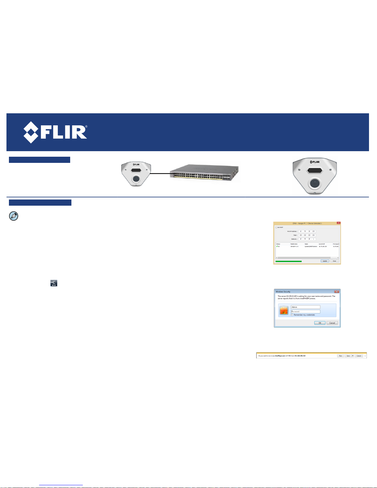
A. Connect the Camera
1. Insert a cable in the RJ45 connector to attach to
the network switch for a 10/100 Mbps Ethernet and
Power over Ethernet (POE) connection.
B. Discover the Camera
The camera’s web interface can be accessed by
Internet Explorer 10 and higher (32-bit) with the ActiveX
plug-in and by browsers that do not support ActiveX,
such as Microsoft Edge, Chrome or Firefox, on PCs
running 64-bit Windows 7, 8, 8.1, or 10.
B.1. Configuring the camera on your workstation
for the first time
1. Install the CD in the product package or download
FLIR’s Discovery Network Assistant (DNA) utility from
the Support > FLIR Firmw are & Software Downloa ds
page at http://www.flir.com /se curity.
2. Cl ick the DNA icon and run DNA version 2.1.2.19
or higher to log into the unit.
3. Attach the unit to the same LAN segment as the
computer that is managing the unit. DNA automatically
discovers the unit on the network and displays the
device’s current IP address in the Discover List.
4. Select the unit from the Dis cover List.
5. Select PAL or NTSC by selecting the unit and clicking
Change Video Format from the context menu, or from
the Properties > Device Properties screen.
6. Click Update.
B.2.a Managing the camera with Horizon, Meridian or on
a DHCP-enabled network
If the camera is managed by Horizon configured as a DHCP
server, or is on a network with a DHCP server, the camera
automatically receives an IP address.
1. Open DNA. The unit is automatically discovered on the network.
See s ection B.1 for ins tructions how to install DNA.
2. Verify that the unit is displayed in the Discover List. The unit
status should be di splayed as Online and Authenticated.
B.2.b Managing the camera with Latitude or on a network
with static IP configuration
If the camera is managed by Latitude or is on a network without
a DHCP server, manually enter its IP address in DNA.
1. Open DNA. The unit is automatically discovered on the network.
See s ection B.1 for ins tructions how to install DNA.
2. If you use non-default credentials, the unit might become
unauthenticated. In this case, authenticate the unit:
a. Use DNA to select the unit(s).
b. Right-click or click the Login button.
c. Enter the camera's User Name ("Admin") and Password
("1234").
d. Click Login.
3. In the DNA Assign IP screen , unche ck Use DHCP, and enter
the unit’s IP, Mask and Gateway IP address es. If the camera
is not authenticated, you m ust first authenticate it.
4. Click Update.
B.3. Log into the Unit
1. Click the unit in the Dis cover Lis t. The Login window opens.
2. Enter the default Us er Name ("Admin") and Pas sword
("1234") which are cas e-sensitive. Then click OK.
3. Click Login in DNA. The unit’s web interface opens.
4. If using IE, click the m essage to ins tall the ArielPlayer plug-in.
5. Follow the on-screen instructions to install the plug-in.
Page 2
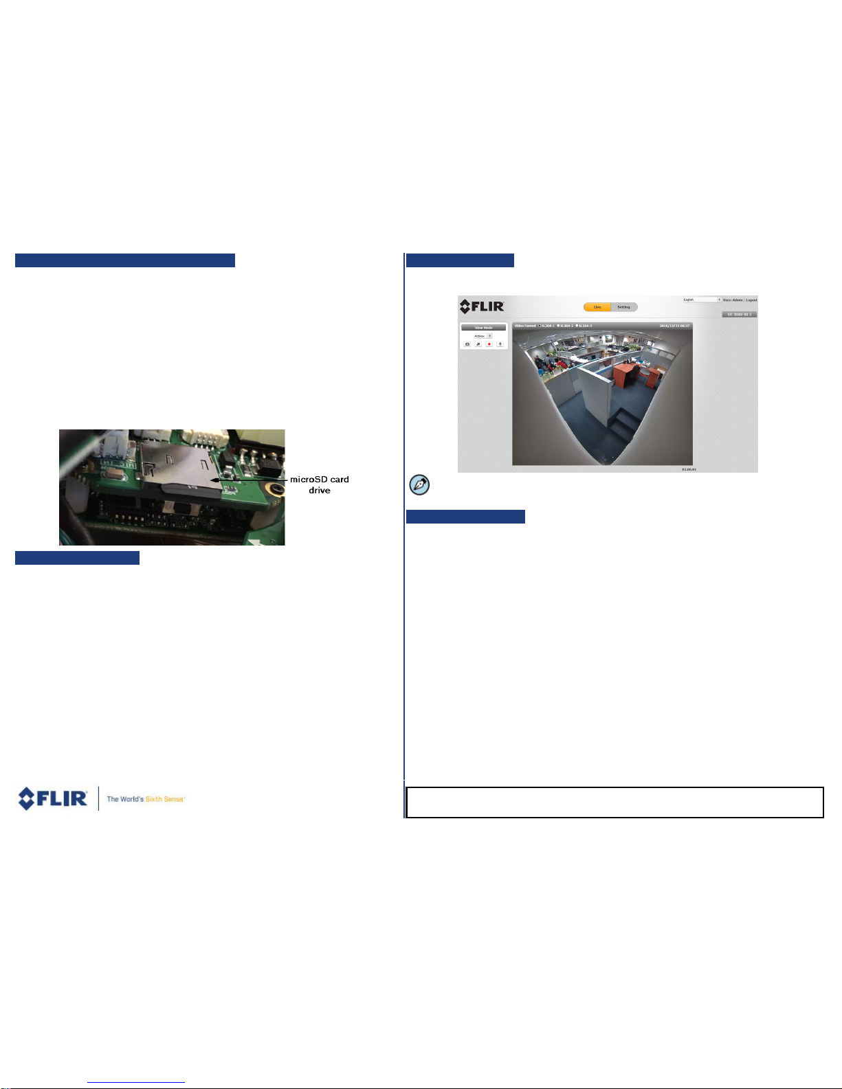
C. Insert and Configure microSD Card
A microSDXC card (not supplied) must be inserted in the camera in order to locally store
a snapshot or recording triggered by an event. The microSDXC card drive is located on a
printed circuit board inside the camera housing. To install a microSDXC card:
1. After removing the camera's cover, insert a m icroSDXC card (up to 64GB, Clas s 10) in the
card drive.
2. Be sure that a new desiccant is inserted inside the enclosure.
3. Replace the cover and s crew the enclosure shut.
4. Verify that the card status is displayed as mounted in the System > Events Handler >
SD Card screen.
5. Format the card.
6. Configure the camera to store snaps hots and recordings from the System > Events Source
screens.
D. Mount the Camera
The CC-3103 camera is designed to be mounted against the ceiling and two walls in the
corner of a room. The enclosure includes screw holes on three sides.
1. Verify that the operating tem perature range is between -40°C ~ 50°C (-40° ~ 122°F),
0-90% relative hum idity (non-cond ensing ).
2. Mount the cam era at the site according to your surveillance requirem ents. Be sure to have
the required access ories and tools available.
3. Using the provided template, mark the drill locations on the ceiling and wall.
4. Drill a hole in the ceiling to insert the system cable if neces sary.
5. Drill holes into the surfaces for the screws.
6. Hammer the screw anchors into place.
7. Attach the s ys tem cable to the network switch.
8. Align the screw holes on the camera body with the markings on the surface.
9. Using the electric screwdriver, screw the camera body into the surfaces.
10. Rem ove the protective plastic covering over the cam era body.
11. Attach the safety lanyard from the base unit to the cover.
12. Using the Torx wrench, screw the camera cover over the camera body.
E. Open Live View
1. Select the Live tab.
2. Click the red recording icon on the Live screen to s tart recording.
This step can be set automatically by FLIR’s Latitude, Horizon or Meridian VMS.
F. Attach to Latitude
Before performing these steps, be sure to install Latitude Update 7.0.0.5775 or higher.
1. In Latitude, click Physical View on the sidebar.
2. On the Navigation Tree, click the system name.
3. From the Discovery tab, do the following:
a. Under Cam eras and Encoders, s elect DVTel Ari el Lin e (Latitude 7) or FLIR (Latitude 8).
b. Click Start. The cam era details are displayed in the Discovery table.
c. If the camera was not dis covered, click Discover Unit Manually.
d. Enter the cam era’s IP address , select DVTel Ariel Line (L atitude 7) or FLIR and Auto Detect
(Latitude 8).
e. Click OK.
4. In the Discovery table, right-click the camera.
5. Select Attach.
6. Click the Archiver name to attach.
7. Click Save.
CC-3103_QIG_16May17_v3
FLIR Systems, Inc. 6769 Hollister Ave. Goleta, CA 93117
Tel: +1 888.388-3577 product.enterprise.support@flir.com www.flir.com/security
 Loading...