

Page 1
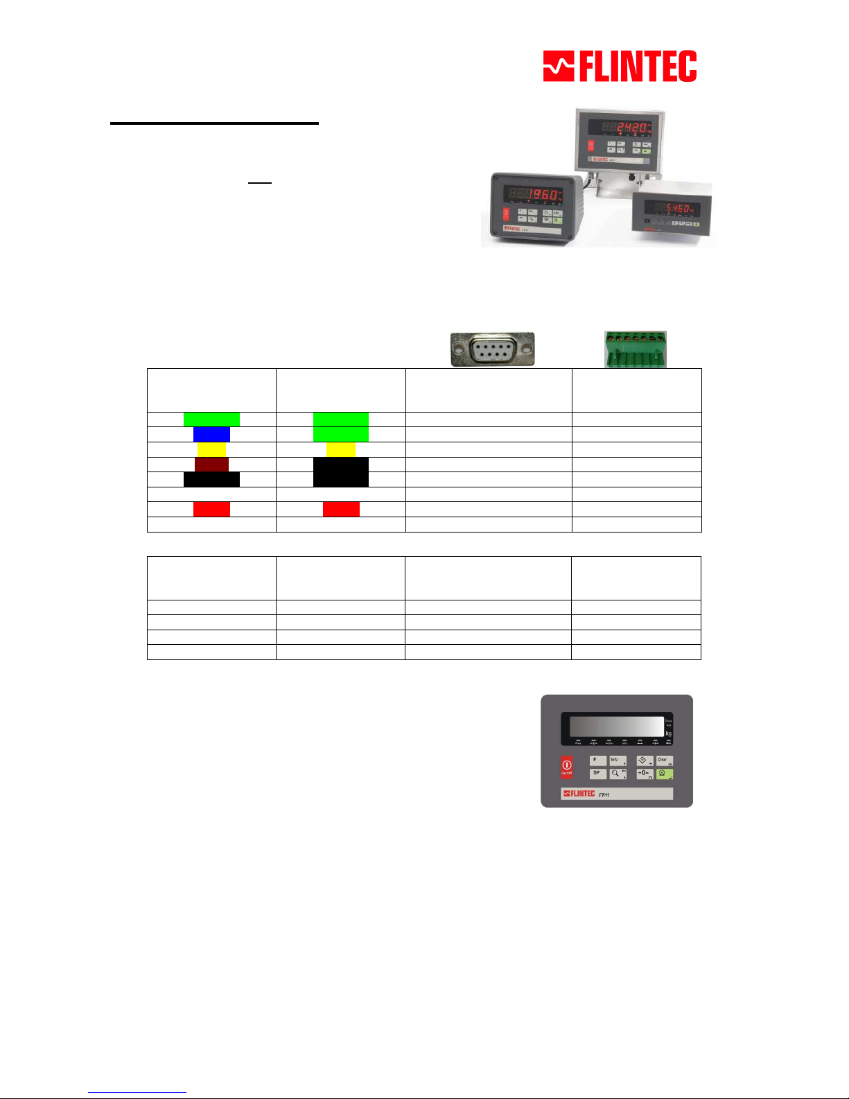
FT-1x Quick Start, May 2012
FT-1x Quick Start
Important hint:
This instruction note does NOT replace the technical manual
It is only a brief survey for the commissioning of a type FT-1x
indicator.
1. All mechanical assembly has to be done properly
2. Execute electrical connections
Connect load cell with FT-1x:
Optional FT-1x to PC communication:
RS232,
PC typical allocation
Definition
D-Sub, 9-pole, female
Desk type housing and
panel type housing
Plug connector J11
Stainless steel housing
2 TxD 3 3
3 RxD 2 4
5 GND 7 2
Shield Connector casing 1
3. Setup the scale
1. Turn on the instrument and wait for the start up.
2. Access the menu for setup and calibration. Here you have
to press following keys in sequence:
<F> and <Info> and ->0<- and <Info> and <Enter>
With the <↑> and <↓> keys you select the parameter block [XXX], with the <Enter> key you confirm
your selection. The <F> key is used to exit the setup.
3.1 Weight display
Se
lect parameter
[212]
and confir
m with the
<
Tare> key.
[CAP]
The capacity of the scale will be entered
by
the <Tare
> and <
Zero
> keys.
The value will be confirmed by pressing the <Enter> key.
[d]
The d
isplay resolution of th
e scale will be selected by
the <Zero
> key.
The selection will be confirmed by pressing the <Enter> key.
6-wire load cell 4-wire load cell
D-Sub, 9-pole, female
Desk type housing and
panel type housing
Plug connector J12
Stainless steel housing
+ Excitation + Excitation 1 1
+ Sense + Excitation 2 2
Shield Shield 3 4
- Sense – Excitation 4 6
– Excitation – Excitation 5 7
+ Signal + Signal 7 3
– Signal – Signal 8 5
Shield Shield Connector casing 4
Page 2
FT-1x Quick Start, May 2012
Muster
3.2 Calibration
3.2.1 Calibration with test weights
[301 ]
Message
[ZEro.CA
]
is displayed
• Unload the scale and confirm with the <Enter> key
• Load the scale with the recommended weight or select another
weight value
• Confirm the [SAvE] message with the <Enter> key
• Press the <F> key twice to exit the menu
• Confirm further [SAvE] messages with the <Enter> key
The calibration with test weights has been succesfully finalized – the scale is now ready for use!
3.2.2 Electronic calibration (eCal)
Hints: Previous to eCal you have to define the scale capacity and the resolution (see section 3.1.)!
Figure: Individual Final Data
Summary document (is part of
the shipment of each load cell)
[313 ]
Start
e
Cal
by
pressing
the <
Tare> key
[LC.CAP ] Enter the total load cell capacity (in kg) by using the <Tare>
and <Zero> keys.
Example: Scale with 4 load cells and 1000 kg for each => Enter: 4000
[LC.oUt ] Enter the rated output (in mV/V) by using the <Tare> and
<Zero> keys. The values can be taken from the individual Final Data
Summary document (see figure on the left).
Example for scale with 4 load cells:
LC1 = 2.0010; LC2 = 1.9998; LC3 = 1.9986; LC4 = 2.0002 =>
(2.0010 + 1.9998 + 1.9986 + 2.0002) / 4 => Enter: 1.9999 (average
value of all load cells)
[ZEr.AdJ] If the scale is empty you can adjust the zero now. If you
prefer to enter the estimated preload value, press the <↑> key.
[PrE-Ld] Enter the scale’s dead load (in kg) by using the <Tare> and
<Zero> keys.
Hint: Is the dead load not exactly known, then you should enter „0“
here. After save and restart of the weighing function the following
weighing result is identical to the real dead load value of the scale.
Note this value and repeat the eCal procedure with a known dead
load value.
[SAvE] Confirm the calibration by pressing the <Enter> key or press
the <F> key to quit without saving this eCal calibration.
The electronic calibration has been succesfully finalized – the scale is now ready for use!
Using the Indface Software
Optionally you can connect the indicator with a PC via serial RS232 interface and you can use the Indface
Software for instrument setup and calibration. The Indface Software can be found on the Flintec-DVD or on
our homepage for download (www.flintec.com).
For further settings and detailed information you have to consult the technical manual of the instrument.
 Loading...