

Page 1
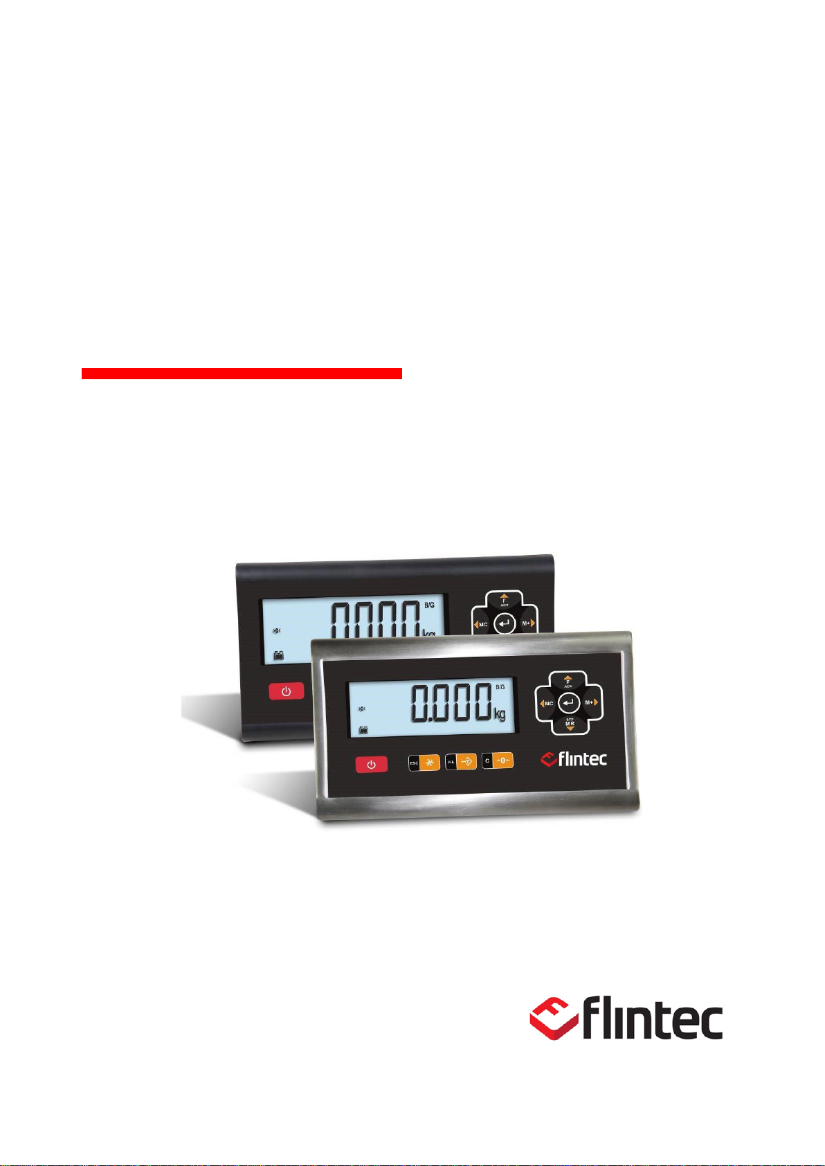
FT-107
Weighing Terminal
Technical Manual
Page 2

FT-107 Weighing Terminal, Technical Manual, Rev. 1.0.0, August 2019 Page 2 of 46
Table of Contents
1. Safety Instructions .................................................................. 5
2. Declaration of Conformity ....................................................... 6
3. Introduction ............................................................................. 7
3.1 Overview ................................................................................................................. 7
3.2 Specifications .......................................................................................................... 7
3.3 The Front View and Key Functions ......................................................................... 8
3.3.1 Display .................................................................................................................... 8
3.3.2 Key Pad .................................................................................................................. 9
3.4 Installation Parts .................................................................................................... 10
3.4.1 Parts included for FT-107 ...................................................................................... 10
3.4.2 Part included for FT-107S ..................................................................................... 10
4. Installation ............................................................................. 11
4.1 Recommendations ................................................................................................ 11
4.1.1 Environment ................................................................ ................................ .......... 11
4.1.2 Cabling .................................................................................................................. 11
4.1.3 Cleaning ................................................................................................................ 11
4.1.4 Disposal ................................................................................................................ 11
4.2 Housing ................................................................................................................. 12
4.3 Mechanical Installation .......................................................................................... 12
4.4 Electrical Connection ............................................................................................ 13
4.4.1 Load Cell Connection ............................................................................................ 14
4.4.2 RS 232C Serial Port .............................................................................................. 15
4.4.3 Optional RS232C Serial Port ................................................................................ 16
4.4.4 Power Source Connection and Grounding ............................................................ 16
5. FT-107(S) Functions ............................................................. 17
5.1 Basic Functions ..................................................................................................... 17
5.2 Advanced Functions .............................................................................................. 19
5.2.1 PLU Memory Menu ............................................................................................... 19
5.2.2 ALU Memory Menu ............................................................................................... 19
5.2.3 CLU Memory Menu: .............................................................................................. 19
5.2.4 Manual APW entry: ............................................................................................... 20
5.2.5 Buzzer Menu ................................ ................................ ................................ ......... 20
5.2.6 Backlight Menu (only FT-107S) : ........................................................................... 21
5.2.7 Configuration Menu: .............................................................................................. 22
5.2.8 Serial Data Outputs: .............................................................................................. 25
5.2.9 Printer setting ........................................................................................................ 27
5.2.10 Date and Time ...................................................................................................... 28
5.3 Unit Change .......................................................................................................... 29
6. Application Weighing ............................................................ 29
6.1 Piece Counting ...................................................................................................... 29
6.2 Checkweighing (+/-) .............................................................................................. 32
6.3 Animal Weighing ................................................................................................... 34
6.4 Temporary Gross Weight Indication ...................................................................... 34
Page 3

FT-107 Weighing Terminal, Technical Manual, Rev. 1.0.0, August 2019 Page 3 of 46
7. Programming and Calibration ............................................... 35
7.1 Entering the Programming and Calibration ................................ ........................... 35
7.2 Exiting the Programming and Calibration .............................................................. 36
7.3 Fast Access to the Calibration .............................................................................. 37
7.4 Programming and Parameters .............................................................................. 38
7.4.1 [ OIML: 0 ] OIML.................................................................................................. 38
7.4.2 [ InCr : 0 ] Increased Display Resolution ............................................................ 38
7.4.3 [ ZrnG: 1 ] Zero Range ........................................................................................ 38
7.4.4 [ PZer: 1 ] Power on Zero Range ....................................................................... 38
7.4.5 [ AZT : 1 ] Automatic Zero Tracking .................................................................... 38
7.4.6 [ StbL: 0.5 ] Stability Delay ................................................................................... 39
7.4.7 [ Motd: 1 ] Motion Detection ................................................................................. 39
7.5 Calibration ............................................................................................................. 40
7.5.1 [ CALıB ] Scale Parameters ................................ ................................................. 40
7.5.2 [ CAL ] Calibration .............................................................................................. 41
7.5.3 [ LınCAL ] Linearity Correction ............................................................................. 41
7.5.4 Zero and Span Adjustment ................................................................................... 41
7.5.5 [ GrAvit ] Gravity Adjustment ................................ ................................ ................ 42
8. Serial Data Formats .............................................................. 43
9. Sealing of Approved Scale .................................................... 44
10. Trouble Shooting ................................................................... 45
Page 4

FT-107 Weighing Terminal, Technical Manual, Rev. 1.0.0, August 2019 Page 4 of 46
RIGHTS AND LIABILITIES
All rights reserved.
No part of this publication may be reproduced, stored in a retrieval system, or transmitted in any form or
by any means, mechanical, photocopying, recording, or otherwise, without the prior written permission of
FLINTEC GMBH.
No patent liability is assumed with respect to the use of the information contained herein. While every
precaution has been taken in the preparation of this book, FLINTEC GMBH assumes no responsibility for
errors or omissions. Neither is any liability assumed for damages resulting from the use of the
information contained herein.
The information herein is believed to be both accurate and reliable. FLINTEC GMBH, however, would be
obliged to be informed if any errors occur. FLINTEC GMBH cannot accept any liability for direct or
indirect damages resulting from the use of this manual.
FLINTEC GMBH reserves the right to revise this manual and alter its content without notification at any
time.
Neither FLINTEC GMBH nor its affiliates shall be liable to the purchaser of this product or third parties for
damages, losses, costs, or expenses incurred by purchaser or third parties as a result of: accident,
misuse, or abuse of this product or unauthorized modifications, repairs, or alterations to this product, or
failure to strictly comply with FLINTEC GMBH operating and maintenance instructions.
FLINTEC GMBH shall not be liable against any damages or problems arising from the use of any options
or any consumable products other than those designated as Original FLINTEC GMBH Products.
NOTICE: The contents of this manual are subject to change without notice.
Copyright © 2016 by FLINTEC GmbH, 74909 Meckesheim, Bemannsbruch 9, Germany
Page 5
FT-107 Weighing Terminal, Technical Manual, Rev. 1.0.0, August 2019 Page 5 of 46
1. SAFETY INSTRUCTIONS
CAUTION! READ THIS MANUAL BEFORE OPERATING OR SERVICING THIS
EQUIPMENT. FOLLOW THESE INSTRUCTIONS CAREFULLY. SAVE THIS MANUAL
FOR FUTURE REFERENCE. DO NOT ALLOW UNTRAINED PERSONNEL TO
OPERATE, CLEAN, INSPECT, MAINTAIN, SERVICE, OR TAMPER WITH THIS
EQUIPMENT. ALWAYS DISCONNECT THIS EQUIPMENT FROM THE POWER
SOURCE BEFORE CLEANING OR PERFORMING MAINTENANCE. CALL FLINTEC
GMBH ENGINEERING FOR PARTS, INFORMATION, AND SERVICE.
WARNING! ONLY PERMIT QUALIFIED PERSONNEL TO SERVICE THIS EQUIPMENT.
EXERCISE CARE WHEN MAKING CHECKS, TESTS AND ADJUSTMENTS THAT MUST
BE MADE WITH POWER ON. FAILING TO OBSERVE THESE PRECAUTIONS CAN
RESULT IN BODILY HARM.
WARNING! FOR CONTINUED PROTECTION AGAINST SHOCK HAZARD CONNECT
TO PROPERLY GROUNDED OUTLET ONLY. DO NOT REMOVE THE GROUND
PRONG.
WARNING! DISCONNECT ALL POWER TO THIS UNIT BEFORE REMOVING ANY
CONNECTION, OPENING THE ENCLOSURE OR SERVICING.
WARNING! BEFORE CONNECTING/DISCONNECTING ANY INTERNAL ELECTRONIC
COMPONENTS OR INTERCONNECTING WIRING BETWEEN ELECTRONIC
EQUIPMENT ALWAYS REMOVE POWER AND WAIT AT LEAST THIRTY (30)
SECONDS BEFORE ANY CONNECTIONS OR DISCONNECTIONS ARE MADE.
FAILURE TO OBSERVE THESE PRECAUTIONS COULD RESULT IN DAMAGE TO OR
DESTRUCTION OF THE EQUIPMENT OR BODILY HARM.
CAUTION! OBSERVE PRECAUTIONS FOR HANDLING ELECTROSTATIC SENSITIVE
DEVICES.
Page 6

FT-107 Weighing Terminal, Technical Manual, Rev. 1.0.0, August 2019 Page 6 of 46
2. DECLARATION OF CONFORMITY
EU-Konformitätserklärung
EU-Declaration of Conformity
Monat/Jahr: month/year:
09/2019
Hersteller: Manufacturer:
Flintec GmbH
Anschrift: Address:
Bemannsbruch 9
D-74909 Meckesheim
Deutschland / Germany
Produktbezeichnung: Product name:
Nr. der Bauartzulassung:
No oft the EC type-examination certificate:
Nichtselbsttätige Waage (NSW)
Non-automatic Weighing Instrument (NAWI)
FT-107 / FT 107S Wägeterminal / Weighing
Terminal
No. 0200-NAWI-07137, FORCE Certification
Das bezeichnete Produkt stimmt mit folgenden Vorschriften der Europäischen Richtlinien überein:
This product confirms with the following regulations of the Directives of the European Community
Richtlinie 2014/35/EU Niederspannungs-Richtlinie
Richtlinie 2014/30/EU EMV
Richtlinie 2011/65/EU RoHS
Richtlinie 2014/31/EU Nichtselbsttätige Waagen
Directive 2014/35/EU Low Voltage Directive
Directive 2014/30/EU Electromagnetic compatibility
Directive 2011/65/EU RoHS
Directive 2014/31/EU Non -Automatic Weighing
Die Absicherung aller produktspezifischen
Qualitätsmerkmale erfolgt auf Basis eines
zertifizierten Qualitätsmanagement-Systems nach
DIN ISO 9001.
All product-related features are assured by a quality
system in accordance with ISO 9001.
Folgende Normen werden zum Nachweis der Übereinstimmung mit den Richtlinien eingehalten:
As a proof of conformity with the directives following standards are fulfilled:
EN 60950-1:2008
EN 61326-1:2013
EN 50581:2012
EN 45501:2015
Diese Erklärung bescheinigt die Übereinstimmung
mit den genannten Richtlinien, beinhaltet jedoch
keine Zusicherung von Eigenschaften.
This declaration certifies the conformity with the listed
directives, but it is no promise of characteristics.
Page 7
FT-107 Weighing Terminal, Technical Manual, Rev. 1.0.0, August 2019 Page 7 of 46
3. INTRODUCTION
3.1 Overview
FT-107 weighing terminal is economic and powerful state-of-the-art indicator for industrial weighing
applications like basic weighing, piece counting, checkweighing or animal weighing.
FT-107 has the capacity for 100 records.
The scales equipped with FT-107 weighing terminal can be used in all kind of industrial areas up to wet and
hygienic environments with its fast and efficient cleaning build to the international guidelines.
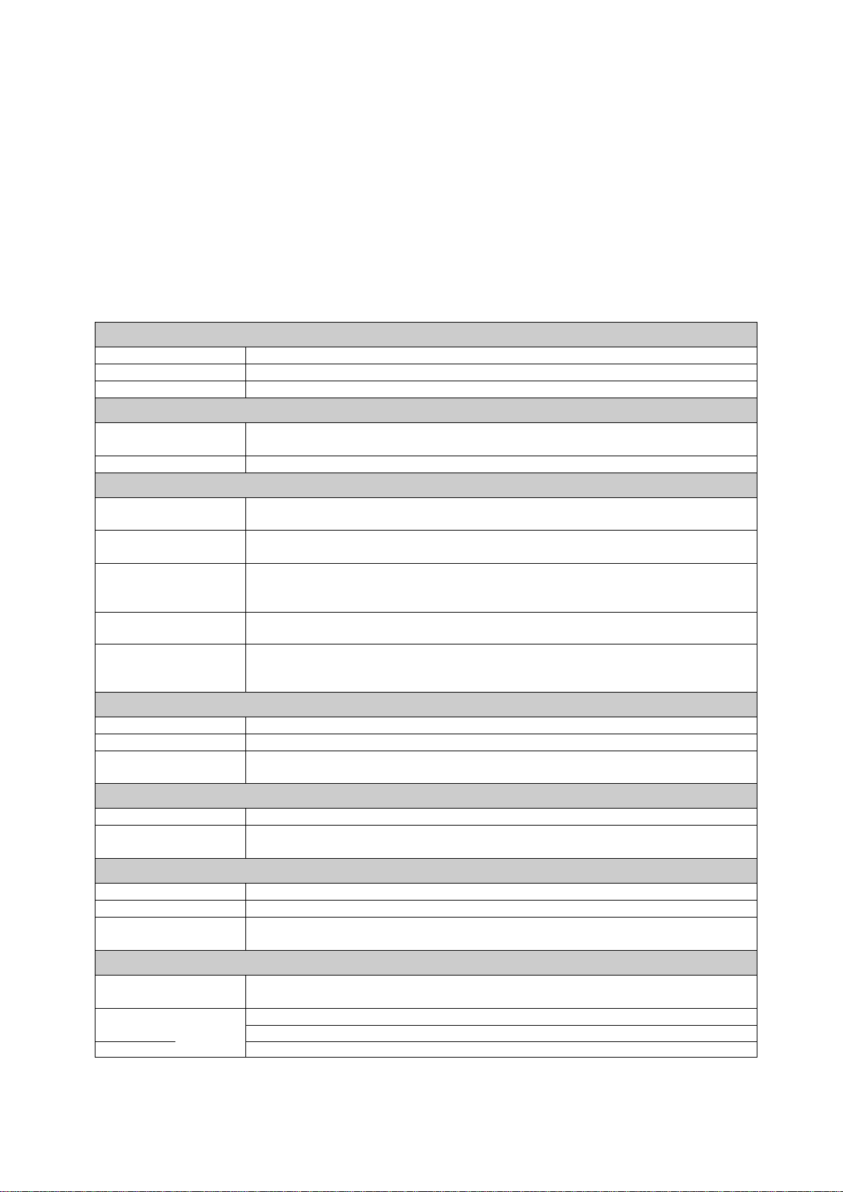
3.2 Specifications
A/D Converter
A/D converter type
24-bit Delta-Sigma ratio metric with integral analog and digital filters
Input sensitivity
0.4 μV/d (approved); 0.1μV/d (non-approved)
Analog input range
0 mV to +18 mV (unipolar)
Resolution
Display resolution
up to 6.000 increment (approved);
up to 30.000 increment (industrial)
Internal resolution
up to 16.000.000
Scale Calibration and Functions
Calibration
Calibration is performed with or without load cell non-linearity correction.
Digital filter
3 steps programmable adaptive digital filter;
4 steps programmable filter at dynamic weighing.
Weighing functions
Taring, zeroing, auto zero tracking, motion detection, auto zero at power up,
increased resolution, unit change, temporary gross weight indication.
Application functions
Basic weighing, check weighing, piece counting, animal weighing, totalization.
Memories
100 product memory at check weighing,
100 product memory at piece counting.
100 product quantity memory at piece counting.
Load cells
Excitation
5 VDC max. 100 mA
Number of load cells
Up to 4 load cells 350 Ω or 12 load cells 1100 Ω in parallel
Connection
4- or 6-wire technique.
Cable length: maximum 2000 m/mm² for 6-wire connection
Communication
RS-232
1200 to 38400 baud rate, 8N1
Second RS-232
(optional)
1200 to 38400 baud rate, 8N1
Power Consumption
FT-107
12 VDC (with 100 – 240 VAC / 12 VDC adaptor)
FT-107S
12 VDC or 100 – 240 VAC, 50-60 Hz
Battery
2000mAh Li-ion, up to 36h continuous operation for single load cell /
24h for 4 x load cells
Environment and Enclosure
Operation
temperature
-15 °C to +55 °C; 85% RH max, non-condensing
Enclosure
FT-107
ABS plastic, IP30;
FT-107S
Stainless steel, IP65
Size
220 x 110 x 55
Page 8
FT-107 Weighing Terminal, Technical Manual, Rev. 1.0.0, August 2019 Page 8 of 46
3.3 The Front View and Key Functions
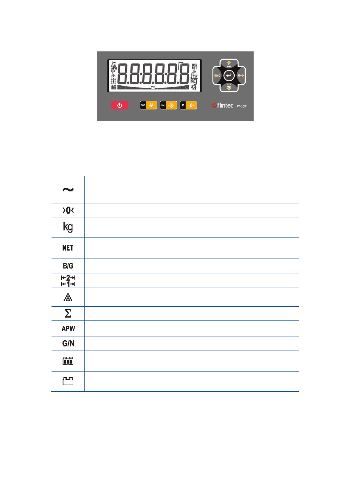
Figure 3.1 – Front view of FT-107(S)
3.3.1 Display
The meanings of the announcement symbols on the display are:
Unstable: This sign appears if the load on the scale is not stable. The weight
value of the object should be read if the scale is stable. The taring, zeroing, printing
and accumulation are available when the scale is stable.
Center of zero: This sign appears if the weight is ±0.25e of the center of the zero.
(Page 17)
Weight unit: The weighing unit is located on the right of the weighting display
as kg, g, lb, and oz.
(Page 29)
Net weight: This sign indicates that the weight indication is in net.
(Page 17)
Gross weight: This sign indicates the displayed weight value is gross.
Operation range: Announces the operation range of the multi range scale.
Piece counting mode: The value on the display indicated the quantity.
(Page 29)
Total: Signs the displayed value is the accumulation in the memory
(Page 18 in weighing and page 30 in piece counting)
APW: Announces the displayed value is the average piece weight.
(Page 31)
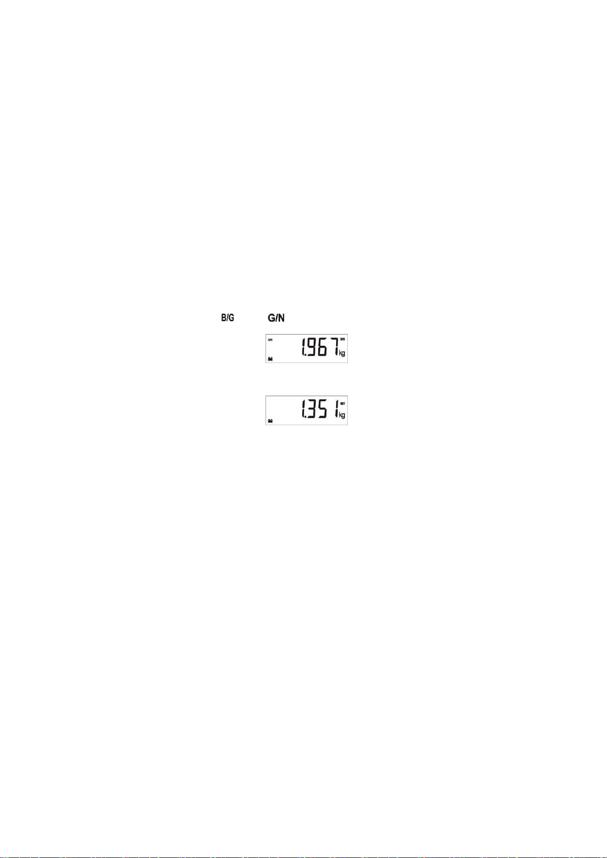
Gross / Net: Temporary gross indication.
(Page 18)
Battery charging level: This sign indicates the battery charging level. Moving
level indicates the battery charging.
Battery is empty: Announces the battery is discharged and should be charged in
a first convenient time.
Page 9
FT-107 Weighing Terminal, Technical Manual, Rev. 1.0.0, August 2019 Page 9 of 46
3.3.2 Key Pad
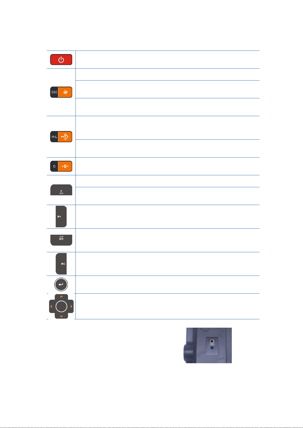
The keys and the key functions of FT-107(S) in usage are:
Power on/off key: Press button to turn it on. To turn it off, press the button for
one second.
* key: The most frequent used function key. Press to use the selected function.
(Page 23)
Sampling key: Press the * key more than one second to start sampling in
piece counting.
(Page 29)
Escape key: In menu mode, press this key to escape from menu and return to
normal mode.
Tare key: Press this key to deduct the weight of the container placed on the
platform to see the net weight value of the added material in the container or
taken out material from the container.
(Page 25)
Checkweighing key: To enter check weighing operation press this key until
[ H-L : n ] message appears.
(Page 32)
Zero key: This key adjusts the scale zero, if there is any drift. Zeroing should
be done if there is no load on the platform.
(Page 17)
F key: This key is used for its programmed function usage.
(Page 23)
ADV key: This key is used to enter advance functions setting by pressing more
than one second.
(Page 19)
M+ Add to memory key: Press this key to add the indicated weight to the
accumulator in weighing and in counting operations.
(Page 18 in weighing and page 30 in piece counting)
MR Memory read: Press this key to indicate accumulated total weight in
weighing operation or accumulated quantity in piece counting operation.
(Page 18 in weighing and page 30 in piece counting)
MC Memory clear key: Press this key to erase accumulated value from
memory. The weight and count accumulators shall be erased separately.
(Page 18 in weighing and page 30 in piece counting)
Enter key: Press this key for printout.
Navigation keys: Navigation keys are located on the right of the indicator
front which are up, down, left and right arrow keys. These keys are used for
navigation in set up and to change any numerical value.
Calibration switch is located on the rear of the
instrument. The calibration switch should be
sealed before putting the scale in to usage.
Page 10
FT-107 Weighing Terminal, Technical Manual, Rev. 1.0.0, August 2019 Page 10 of 46
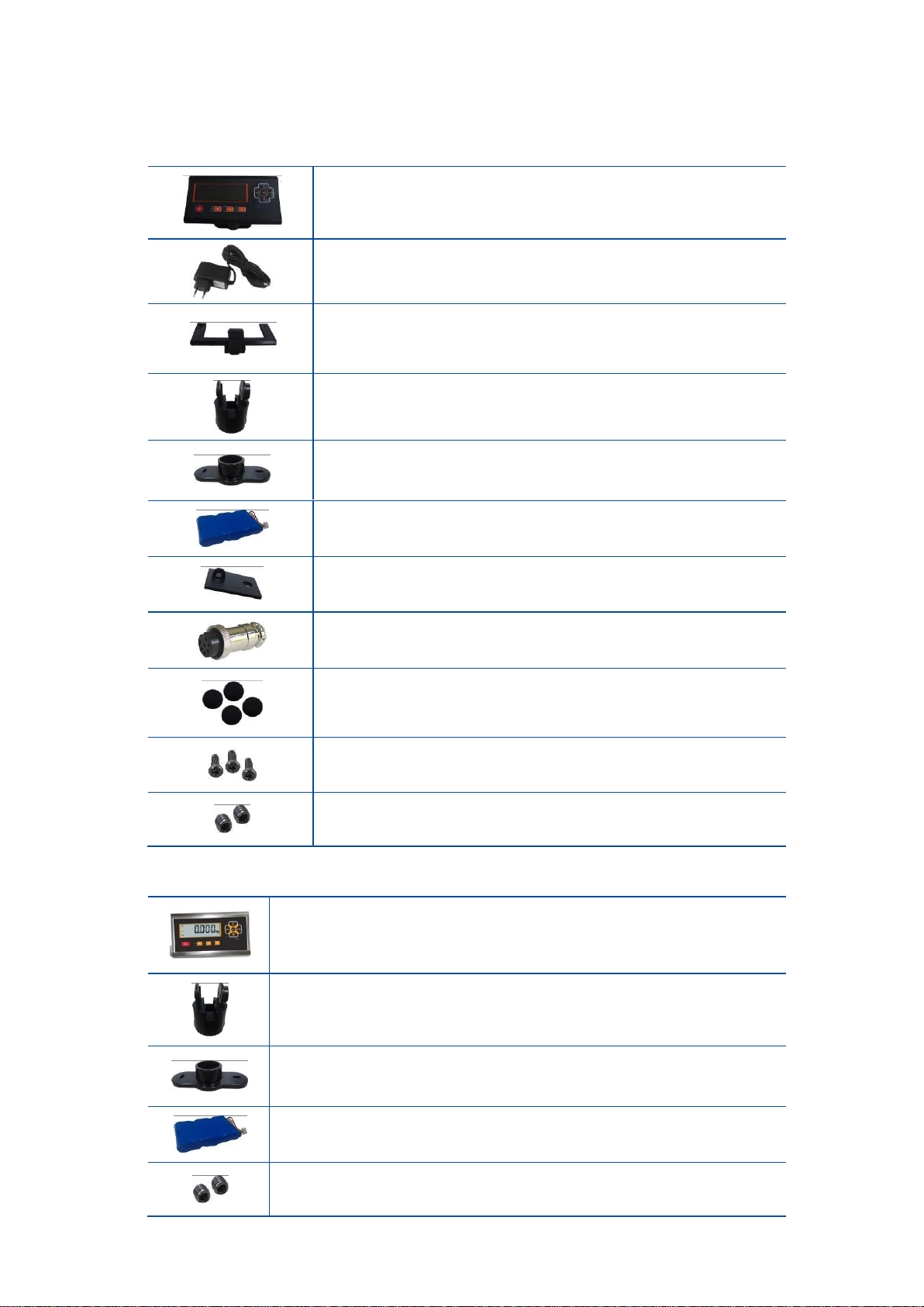
3.4 Installation Parts
3.4.1 Parts included for FT-107
FT-107 Indicator
100VAC - 240VAC, 50 – 60 Hz / 12VDC, 0.8A regulated adapter.
Support plate
(will be mounted on the rear of the indicator)
Column holder
(will be mounted on the support plate)
Wall mounting plate
(will be mounted on the column holder)
Battery BAT21 Li-ion
Sealing kit for sealing with lead
(only approved versions)
1 x Load cell connector
4 x rubber foot for usage on the table
3 x M4 screw for installation to Support plate
2 x allen screws for installation to Column holder
3.4.2 Part included for FT-107S
FT-107S Indicator
Column holder
(will be mounted on the rear of the indicator)
Wall mounting plate
(will be mounted on the column holder)
Battery BAT21 Li-ion
2 x allen screw to install on the indicator support 2
Page 11

FT-107 Weighing Terminal, Technical Manual, Rev. 1.0.0, August 2019 Page 11 of 46
4. INSTALLATION
PRECAUTION: Please read this section carefully before installation of the instrument. Applying the
recommendations in this section will increase your system reliability and its long-term performance.
Before starting the installation,
1. Select the weighing terminal location. Refer to recommendations in the following section.
2. Prepare the PE protective earth cable to grounding the indicator housing. The protective earth
should be as good as possible for scale reliability.
3. Prepare the power source near the weighing terminal.
4. Prepare the cabling tray, pipe etc. from platform to the weighing terminal.
4.1 Recommendations
4.1.1 Environment
Warning: Please care the following warnings for designing your operation area which will increase your
system reliability.
The weighing indicator should be placed clean area, not getting direct sun light if possible, with a temperature
between -10 ºC and +40 ºC, humidity not exceeding 85% non-condensing. All external cables should be
installed safely to avoid mechanical damages.
This instrument is very low-level signal measuring instrument. To avoid electrical noise, it should be separated
from equipment that produces electrical noise. The instrument body shall be connected to a good ground
against the electromagnetic disturbances. Load cell cable must be separated from other cables, if possible. If
there are noise-generating equipment such as heavy load switches, motor control equipment, inductive loads
etc., please be careful against the EMC interference. Connect parallel reverse diodes to the DC inductive
loads like relays, solenoids etc. to minimize voltage peaks on the DC power lines.
4.1.2 Cabling
All cables coming to the instrument shall be high quality and shielded. Distance from load cell cables, interface
cables and DC power supply cables to power line cables shall be minimum 50 cm. The separate cable tray
usage for these low signal level cables is strongly recommended.
Shields of the cables should be connected to the ground.
4.1.3 Cleaning
Warning: Disconnect the instrument from power source before start cleaning for your safety. Cover the
open glands.
FT-107 instrument is designed for using in wet, hygienic and harsh environment. To maintain the instrument,
never use harsh abrasive cleaners or solvents. Wipe the instrument with a soft cloth slightly dampened with
warm soapy water or with mild detergent.
4.1.4 Disposal
In conformance with the European Directive 2002/96 EC Waste Electrical and Electronic Equipment (WEEE),
this device may not be disposed of with domestic waste. This rule also applies to the non-EU countries,
according to their specific regulations. Please dispose of this product in accordance with local regulations at
the collecting point specific for electrical and electronic equipment. For your questions, please contact the
responsible local authority. Thank you for your attention to environmental protection.
Page 12
FT-107 Weighing Terminal, Technical Manual, Rev. 1.0.0, August 2019 Page 12 of 46
4.2 Housing
4.3 Mechanical Installation
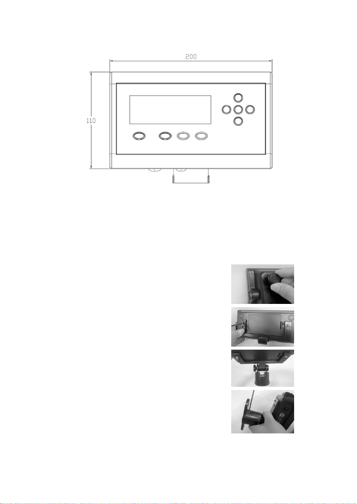
You may install your weighing indicator on a column, on a table or on a wall. Take care of the housing
drawings and dimensions given in this manual to design your weighing scale or weighing station mechanically.
Be sure that the mechanical installation of the instrument is done properly for long time life before starting
electrical installation as descripted below. Installation of the desk type and wall type housings are identical due
to same kits usage as shown below.
If the indicator will be used on the table, stick the 4 pieces
rubber foots on the back of the indicator (only FT-107).
For installation on a round scale column, do not stick the
rubber foot and follow the pictures below.
Install the Support plate to the indicator with 3 pcs M4 screws included
in the box (only FT-107).
Install the Column holder after installing 2 allen screws.
If the indicator will be mounted on the square column or to the
wall, install the wall mounting plate to the column holder
Page 13
FT-107 Weighing Terminal, Technical Manual, Rev. 1.0.0, August 2019 Page 13 of 46
4.4 Electrical Connection
Recommendations
1. Always remember that FT-107(S) indicator is very low voltage measuring instrument in the industrial
environment. Your proper installation increases reliability and performance of the instrument.
2. A trained person should interface the instrument because of the 230 VAC voltage in the instrument
and against malfunction at installation.
3. If the energy condition of your plant is bad, prepare a special power line.
4. The quality of your plant grounding will provide weighing accuracy and the safety of your indicator. If
grounding of your plant is bad, prepare a special power line and grounding.
5. The instrument shall be powered off before interfering the instrument.
6. Powered off the instrument before connecting or disconnecting any peripheral instrument.
7. The shielded cable and ground connection of the shield will increase the immunity against electrical
disturbances.
8. All required electrical connections should be done as described in the installation section below.
9. If you should service the indicator, turn the power off and wait at least 30 seconds before opening
housing to interfere it.
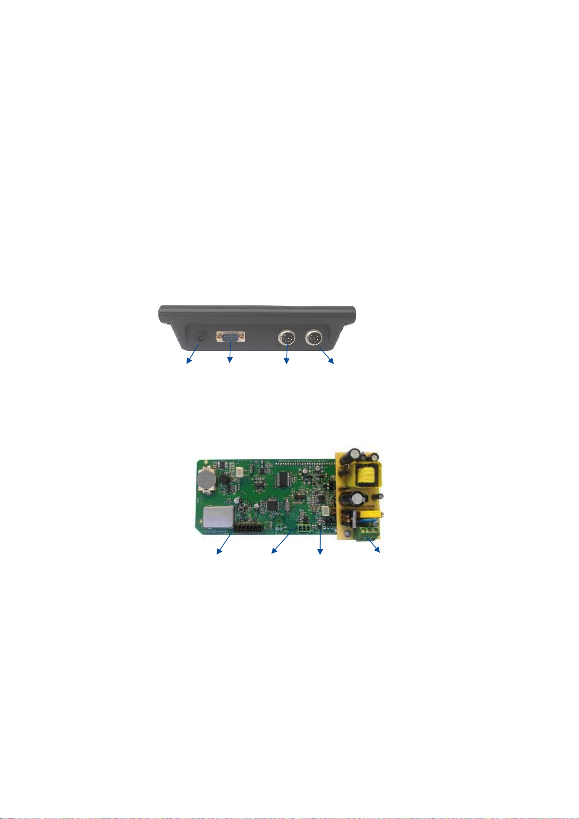
Place of the Peripheral Connections
Power
RS 232C
RS 232C
Load Cell
Supply
(Optional)
Figure 4.1 – FT-107 connections
Figure 4.2 – FT-107S connections
Load Cell
RS 232C
RS 232C
Power
(Optional)
Supply
Page 14
FT-107 Weighing Terminal, Technical Manual, Rev. 1.0.0, August 2019 Page 14 of 46
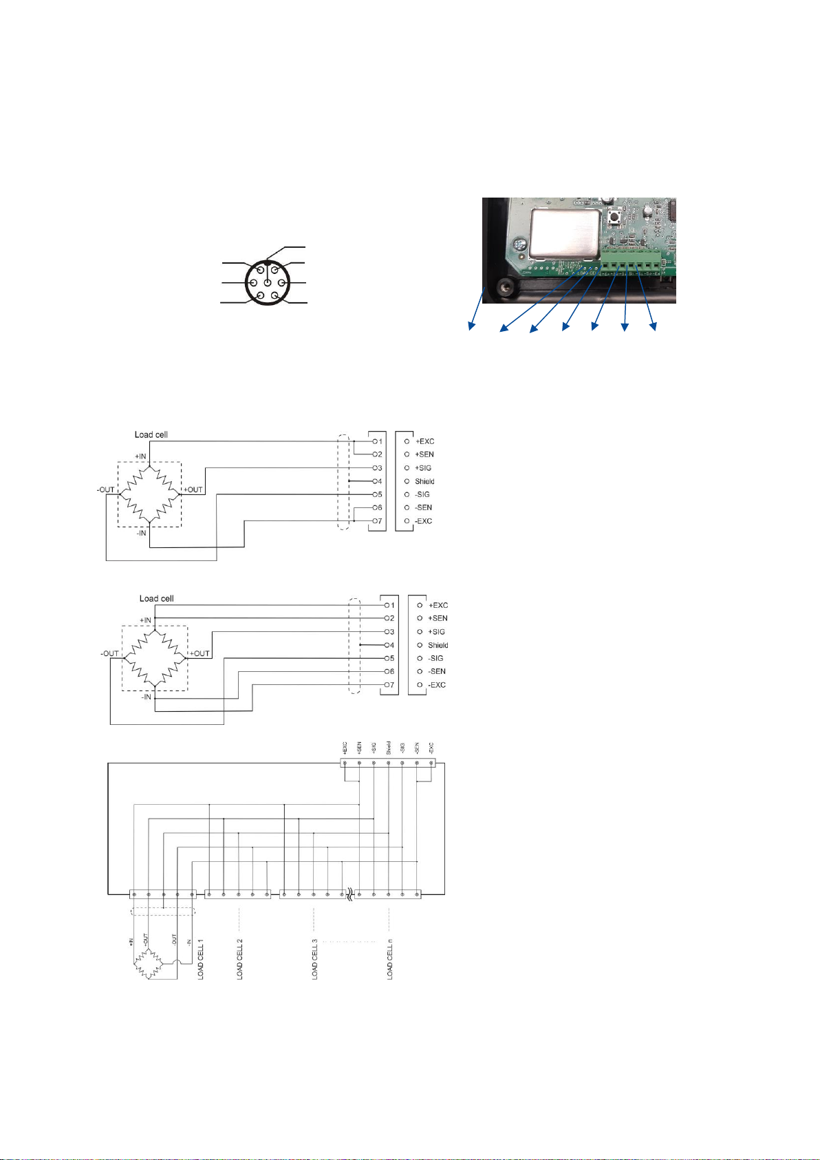
4.4.1 Load Cell Connection
To avoid damages, the load cell wiring should be made carefully before energizing the instrument. Load cell
connection details are shown in Figure 4.4. In 4-wire installations the sense and excitation pins with the same
polarity should be short circuited at the connector side. If you have junction box in your system, use 6 wire
cable between FT-107(S) and the junction box, and short circuit these pins at junction box for better
performance.
FT-107 (rear view) FT-107S
Figure 4.3- The load cell connector
Figure 4.4 – The load cell and junction box connection
Warning: Always connect Sense pins to Excitation pins for 4 wire connection. Non-connected sense pins
may cause the wrong Excitation voltage measurement and create an accuracy problem.
Warning: Connect the load cell cable shield to the housing (recommended to increase the EMC immunity
against disturbances) or shield pin of the load cell connector.
Shld
+Exc
+Sen
+Sig
-Sig
-Sen
-Exc
4 wire load cell connection
6 wire load cell connection
Junction box connection
(6)+ Excitation
(5) Shield
(4) - Sense
- Excitation (3)
+ Signal (2)
- Signal (1)
(7)+ Sense
Page 15
FT-107 Weighing Terminal, Technical Manual, Rev. 1.0.0, August 2019 Page 15 of 46
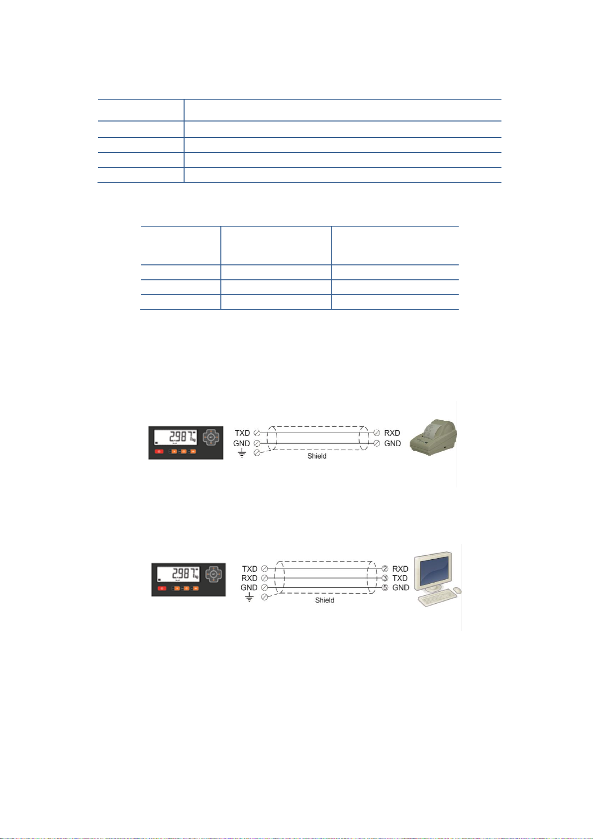
4.4.2 RS 232C Serial Port
FT-107(S) weighing terminal has one standard RS232C and one optional RS232C port.
Usage
Interfacing with printer, PC, PLC, remote display etc.
Data formats
Continuous, Continuous 2, Printer
Baud rate
1200 / 2400 / 4800 / 9600 (Default) / 19200 / 38400 bps
Length and parity
8 bits no parity
Start / Stop bits
1 start bit and 1 stop bit
Table 4.1 - RS 232C Serial Interface Specifications
Definition
FT-107
FT-107S
Pin number
(DB9 male)
Pin number
(Terminal)
TXD 2 1
RXD 3 2
GND 5 3
Table 4.2 – Pin configuration of RS 232C terminals
2-wire connection to peripherals: RS 232C serial connection is done with two wires as indicated below in
Figure 4.5. if there is no data entry to the weighing terminal. Typical applications are printer and barcode
reader connections.
Figure 4.5 – 2 wire RS 232C connection with a printer or PC
3-wire connection to the peripherals: RS 232C serial connection is done with three wires as indicated below
in Figure 4.6 for bidirectional interfacing. Typical application is bidirectional BSI format interfacing with PC or
PLC.
Figure 4.6 – 3 wire RS 232C connection with a PC or PLC
Page 16
FT-107 Weighing Terminal, Technical Manual, Rev. 1.0.0, August 2019 Page 16 of 46
4.4.3 Optional RS232C Serial Port
Usage
Interfacing with printer, PC, PLC, remote display etc.
Data formats
Continuous, Continuous 2, Printer,
Baud rate
1200 / 2400 / 4800 / 9600 (Default) / 19200 / 38400 bps
Length and parity
8 bits no parity
Start / Stop bits
1 start bit and 1 stop bit
Table 4.3 – optional RS232 Serial Interface Specifications
FT-107
FT-107S
Definition
Pin number
(Round Male)
Pin number
(Terminal)
TXD 2 2
GND 3 3
Table 4.4 – Pin configuration of optional RS 232
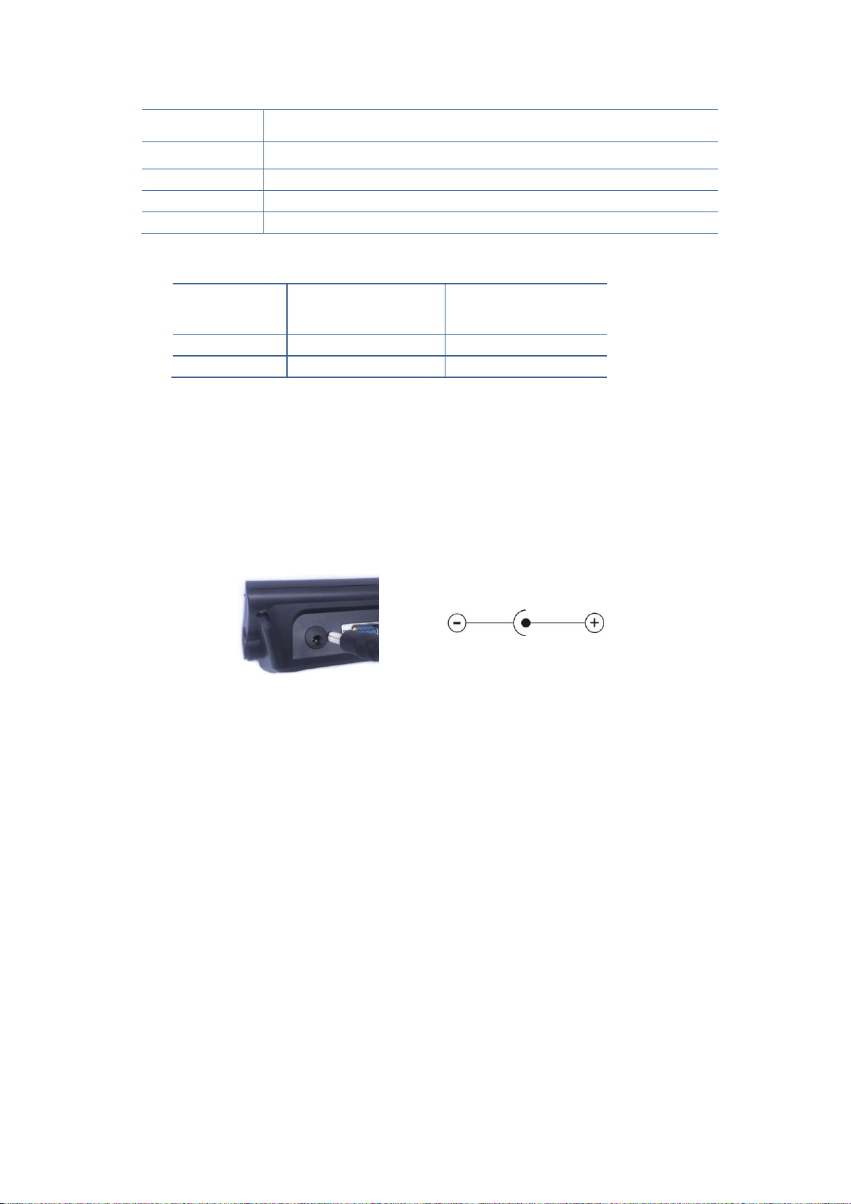
4.4.4 Power Source Connection and Grounding
The weighing instruments measures very low signal levels. The quality of the power line will determine the
accuracy and the safety of your measuring system. It is very important that the instrument should not share
power lines with noise-generating parts such as heavy load switching relays, motor control equipment,
inductive loads, etc. If the condition of the power supply in the plant is poor, prepare a special power line and
grounding. Before connecting the power source check if its voltage is the same as the voltage written on the
weighing terminal.
Table 4.5 – Power supply connector
The protected ground shall be connected to the 230 VAC powered instrument against the safety and electrical
disturbances.
Page 17
FT-107 Weighing Terminal, Technical Manual, Rev. 1.0.0, August 2019 Page 17 of 46
5. FT-107(S) FUNCTIONS
5.1 Basic Functions
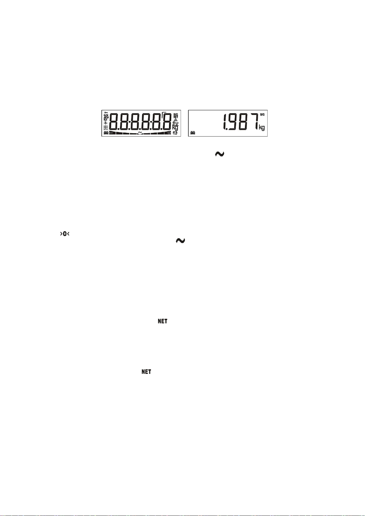
Press [ On/Off ] key to switch on the scale. Indicator activates all segments of the display for a few seconds
then shows indicator´s model name and version. At the end a display test will be carried out.
After starting cycle, the weight value is displayed. The message [ E E E ] will appear at power on if the weight
exceed the zeroing range. The scale should be unloaded before power on.
Figure 5.1 - LCD Display segments and Weight display.
Place the object on the scale. If the scale is stable and the symbol disappeared, the weight will be
displayed.
If one of the function keys (“ * ” or “F” key) were programed for unit changing, press this key to select desired
weighting unit (Page 29 ).
Zeroing
Zeroing is done to compensate deviations from zero of the unloaded scale.
1. Ensure the scale is clean and does not touch any surroundings.
2. Press the Zero key to compensate the zero deviation. The zeroing is done if the scale is stable and
in zeroing range.
3. sign appears to indicate the zeroing is done and the scale is at center of zero.
4. If zeroing is not done properly, wait for the sign disappear and press Zero key again.
Taring
Taring is done to deduct the container weight and to see only the material inside. FT-107 is programmable for
3 types of tare function: Multi tare, Tare/Clear, Automatic tare (Page 25).
Warning: Tare value cannot exceed the maximum scale capacity. The scale capacity in Net is the subtraction
of maximum capacity to the tare weight. Capacity in Net = Maximum capacity – Tare weight.
Multi taring
1. Place the container on the platform and press the Tare key.
2. The display value is zeroed and the (net weight) symbol appears.
3. Place the material into the container and read the net weight.
4. The tare value is used until either a next tare or pressing Tare key after unloading the scale or until
zeroing the scale.
Tare / Clear
1. Place the container on the platform and press the Tare key.
2. The display is zeroed and the (net weight) symbol appears.
3. Place the material into the container and read the net weight.
4. Press the Tare key to clear the tare. Or press the Zero key after unloading the platform.
Auto Tare
This function allows taring automatically after loading the scale in gross operation without pressing Tare key
if the load is bigger than 20e. After unloading the scale, the indication goes back to the gross. To activate the
auto tare function, refer to Advanced functions (Page 25).
1. Place the container on the platform.
2. Scale activates the tare function automatically after stabilization.
3. Place the material inside the container for net weighing.
4. After unloading the scale, the indicator starts to indicate in gross.
Page 18
FT-107 Weighing Terminal, Technical Manual, Rev. 1.0.0, August 2019 Page 18 of 46
Gross / Net Function
You can use the Gross/Net function at any time to switch the display between the net and gross weight, if you
programmed one of the function keys as G/N key. After the G/N key is pressed, the display shows the
gross weight for a few seconds and then automatically goes back to the net weight indication.
Printing
You may connect your indicator to the printer and adjust the RS 232C serial data output related parameters.
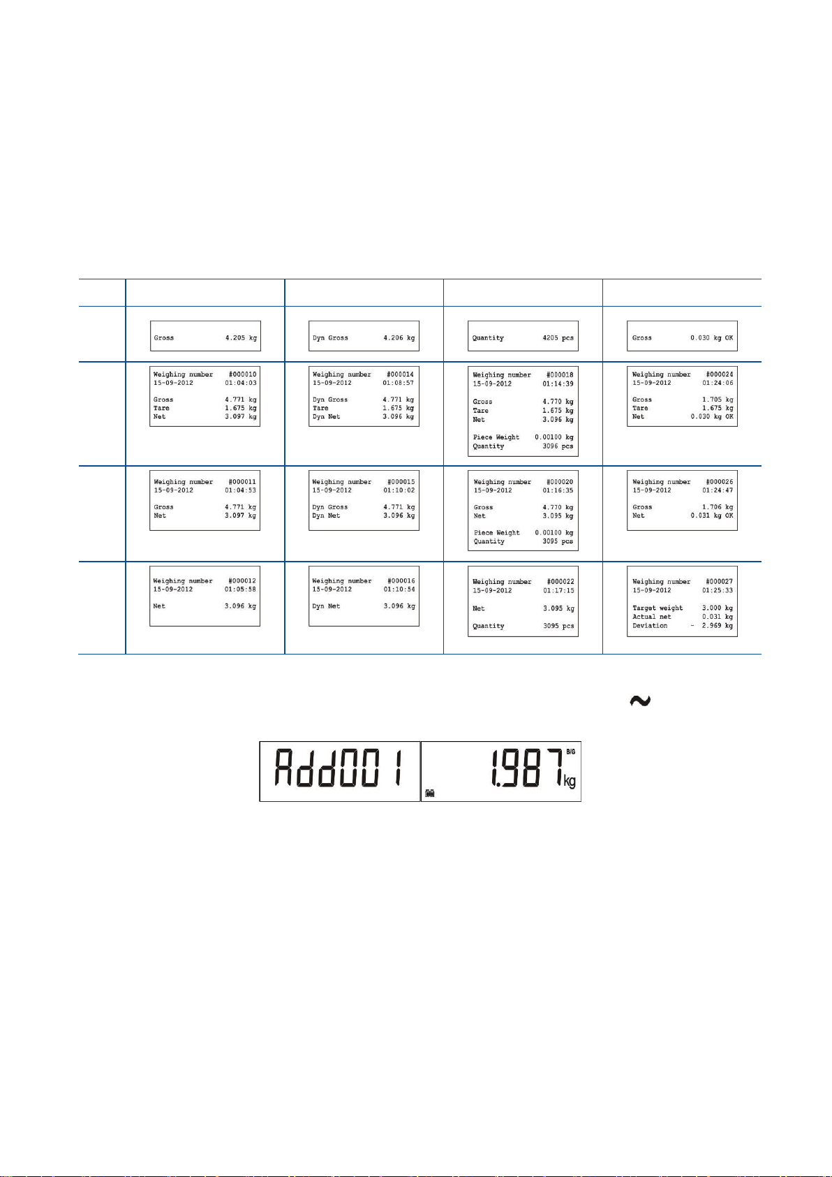
Select the printout ticket form from the table below. Press Enter key to print the ticket if the indication is
stable after loading.
The table below shows different printouts for various operation modes (Page 27). For 16-character printers,
select small printer format which has abbreviated data names.
Ticket
Basic Weighing
Animal Weighing
Piece Counting
Check Weighing
Form
1
Form
2
Form
3
Form
4
Total memory at weighting
To accumulate the weighing values, put an object on the platform, if the scale is stable ( symbol off ),
and press M+ key to add the weight value to the total.
The weight value will be added and accumulation quantity increased. Press M+ for further accumulations.
To see the total value, press MR key and the accumulated value will be displayed.
To print the accumulated value, press Enter key if the accumulated value is displayed. To erase the
accumulation, press MC and accumulated value will be deleted after your confirmation.
Page 19
FT-107 Weighing Terminal, Technical Manual, Rev. 1.0.0, August 2019 Page 19 of 46
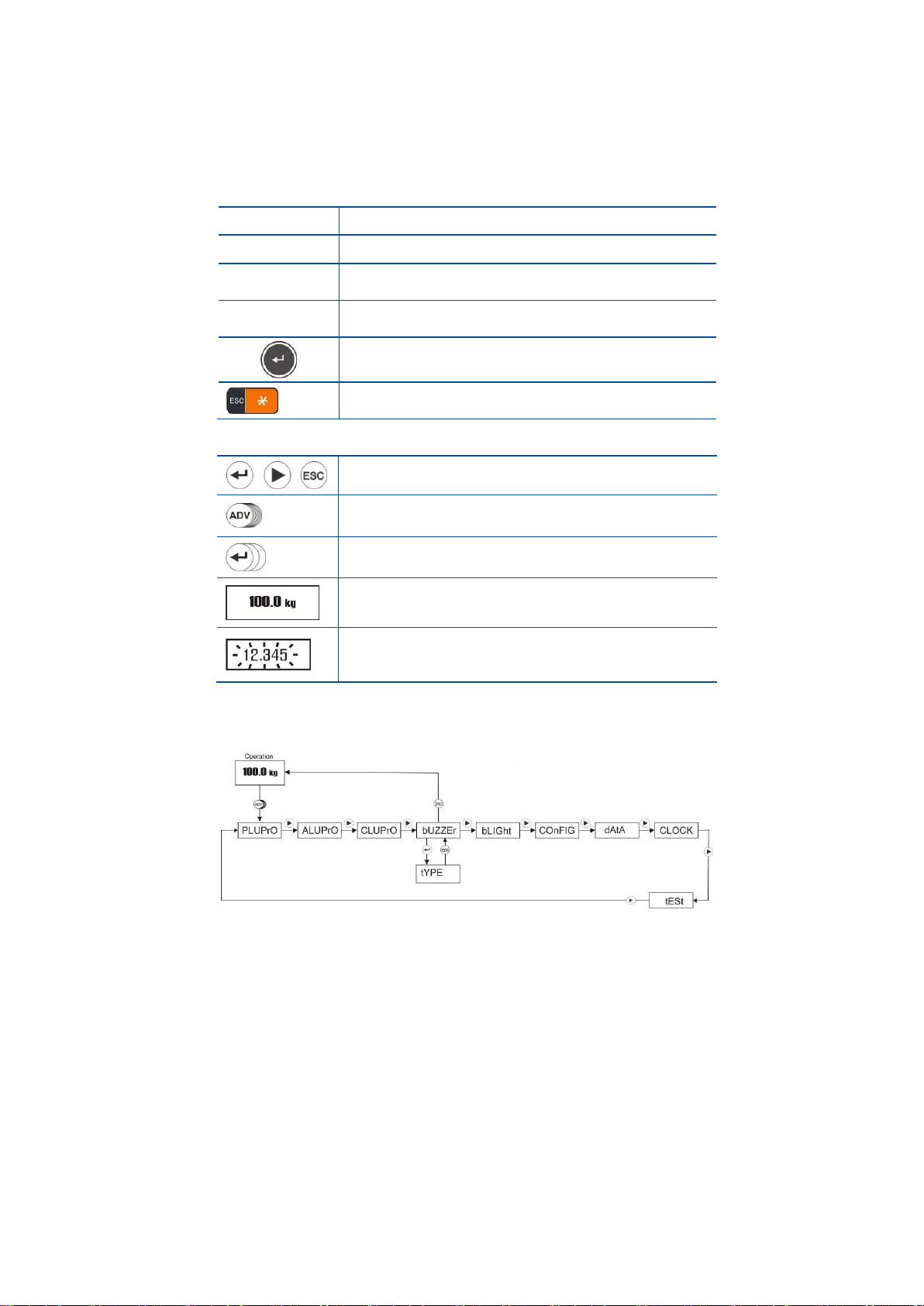
5.2 Advanced Functions
You can change the instrument advanced functions in set-up menu by pressing ADV key longer than one
second.
In ADV menu the navigation key functions are;
▲
- Increase the selected digit value.
▼
- Decrease the selected digit value.
►
- Next menu item,
- Shift the digit to the right to change the value.
◄
- Previous menu item,
- Shift the digit to the left to change the value.
- Enter the menu and menu item,
- Enter the next item.
- Return from item,
- Return to operation from menu.
The symbols in ADV programming diagrams are;
- Press the key in the circle to enter the next step.
- Press the key longer than 1 second until the next
prompt appears.
- Press the key the circle quantity times.
(3 times for the symbol on the left)
- Operation
- Enter the value by pressing navigation keys. Press
► or ◄ keys to shift the digit; press ▲ or ▼
keys to increase or decrease the selected digit.
With the ► key change to the next item. Press Enter key to access items in the selected menu or press
Esc key to return to previous step.
The advanced functions set-up are described in the flow diagrams above.
5.2.1 PLU Memory Menu
PLU memory is used in checkweighing operation. This memory use and data input are described in
checkweighing operation in Section 5.2.1 (Page 32).
5.2.2 ALU Memory Menu
ALU memory is used to check the quantity at piece counting. This memory usage and data input are described
in Section 6.2 (Page 32).
5.2.3 CLU Memory Menu:
CLU memory is used in piece counting operation. This memory usage and APW saving after sampling are
described in to the piece counting operation in Section 6.1 (Page 29).
Page 20
FT-107 Weighing Terminal, Technical Manual, Rev. 1.0.0, August 2019 Page 20 of 46
5.2.4 Manual APW entry:
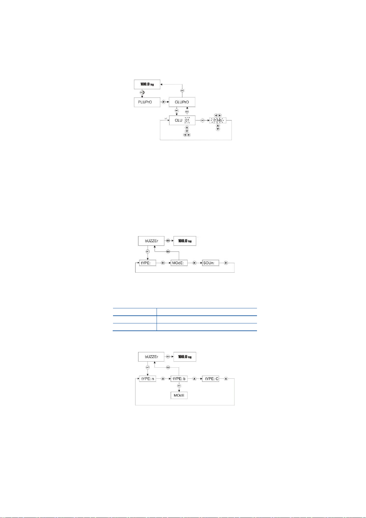
FT-107 indicator has 100 memory locations for counting various materials. The data entry to the CLU
memory is carried out in Advanced functions menu by pressing ADV key longer than one second.
Follow the diagram below to entry the APW (average piece weight) of the material into the CLU memory.
CLU code increases or decreases by pressing ▲ or ▼ keys. The APW value’s digit can be selected by
pressing ► or ◄ keys and the digit value can be increased or decreased by pressing ▲ or ▼
keys.
Press Esc key 2 times to return to operation.
5.2.5 Buzzer Menu
To access to Buzzer related functions menu, press ADV key longer than one second until [ PLUPrO ]
message appears on the display. Press ► until [ bUZZEr ] prompt appears.
Buzzer Sound type at Checkweighing
The buzzer sound can be programmed as a continuous or only a 3-seconds warning as shown below.
n
No sound.
b
One-time warning for 1 second
C
Continuous warning
Press Enter key to access Buzzer sound type item at [ bUZZEr ] prompt.
Press Enter key to go to the following item or press Esc key to go previous step after selecting
buzzer sound type by ▲ key.
Page 21
FT-107 Weighing Terminal, Technical Manual, Rev. 1.0.0, August 2019 Page 21 of 46
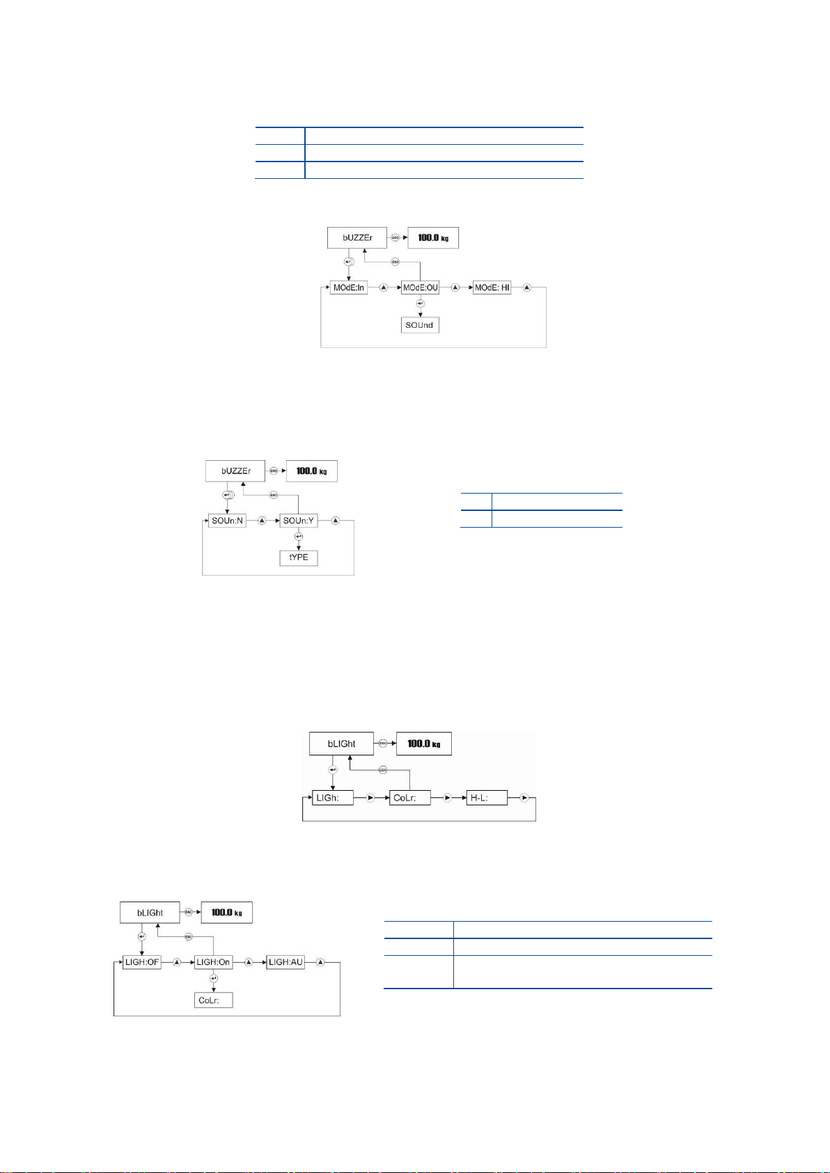
Buzzer Mode at Checkweighing
Buzzer warning can be done as shown in the table below.
Ou
Warn when weight is out of tolerance.
in
Warn when weight is in the limits.
Hi
Warn when weight is over the high limit.
Press Enter key 2 times in Buzzer menu to access the warning mode item.
Press Enter key to enter the next item or press Esc key to enter the previous step after selecting
warning mode by ▲ key.
Keypad Sound
Buzzer sounds after pressing any key. Press Enter key 3 times in Buzzer menu to access this item.
Press Enter key enter the next item or press Esc key enter the previous step after selecting keypad
sound by ▲ key.
5.2.6 Backlight Menu (only FT-107S) :
To access the Backlight menu, press ADV key longer than one second until [ PLUPrO ] message appears on
the display. Press ► key several times until [ bLiGht ] prompt appears. You can program the backlight
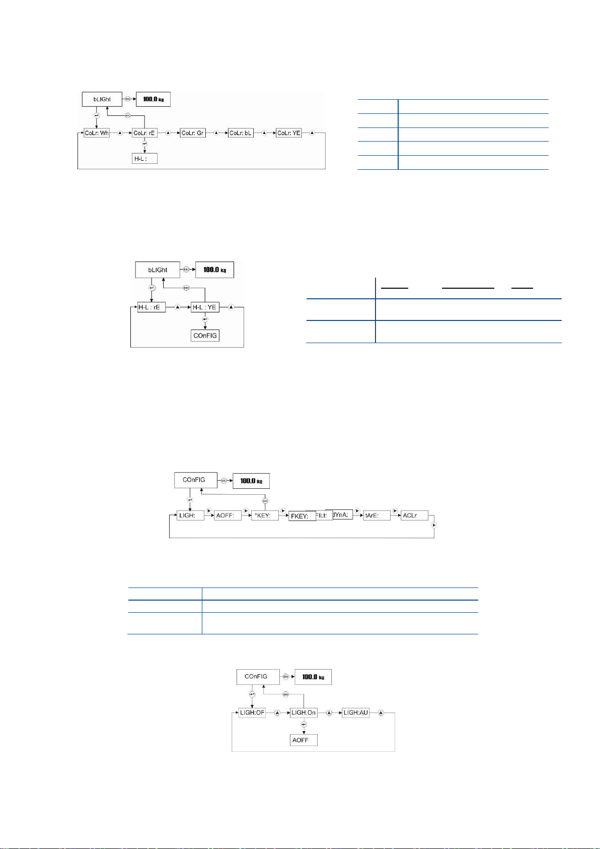
operation, backlight color at basic weighing and back light warning at over – under operation in this menu.
Backlight
Press Enter key in Backlight menu to access the backlight adjustment item.
Press Enter key to enter the next item or press Esc key to return to the previous step after selecting
backlight by ▲ key.
n
Keypad Sound off.
Y
Keypad Sound on.
OF
Backlight always off.
On
Backlight always on.
AU
Backlight turns off, if the scale is not
used 5 seconds.
Page 22
FT-107 Weighing Terminal, Technical Manual, Rev. 1.0.0, August 2019 Page 22 of 46
Color
You may program backlight color in this item as shown below.
Press Enter key to enter the next item or press Esc key to return to the previous step after selecting
backlight color by ▲ key.
H-L Color
You may program backlight color in check weighing operation.
Press Enter key to enter the next item or press Esc key to return to the previous step after selecting
backlight color by ▲ key.
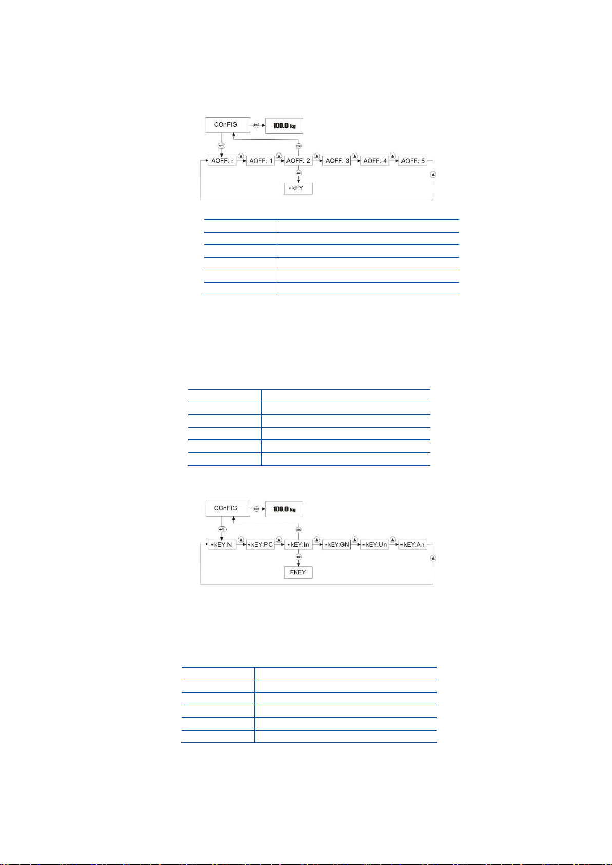
5.2.7 Configuration Menu:
To access to Configuration menu, press ADV key longer than one second until [ PLUPrO ] message
appears on the display. Press ► key several times until [ COnFIG ] prompt appears.
Backlight (only FT-107)
You may program backlight operation in this item as seen below.
On
Backlight always on.
OF
Backlight always off.
Au
Backlight turns off, if the scale is not used 5 seconds.
Press Enter key in Configuration menu to access the backlight adjustment item.
Press Enter key to go to the following item or press Esc key to go previous step after selecting
backlight by ▲ key.
Wh
Backlight color is white.
rE
Backlight color is red.
Gr
Backlight color is green.
bL
Backlight color is blue.
YE
Backlight color is yellow.
Under In tolerance Over
rE
Red Green Yellow
YE
Yellow Green Red
Page 23
FT-107 Weighing Terminal, Technical Manual, Rev. 1.0.0, August 2019 Page 23 of 46
Auto Power off
The indicator is programmable for automatic power off to increase the battery life, if the scale is not used
for some period. Press Enter key 2 times in Configuration menu to access the backlight adjustment
item.
Press Enter key to enter the next item or press Esc key to return to step after selecting auto power off
by ▲ key.
* key usage
You can select this key function from the table below.
n
Disable.
PC
Piece count
In
Increased resolution
Gn
Temporary Gross indication in Net
Un
Unit change
An
Animal weighing
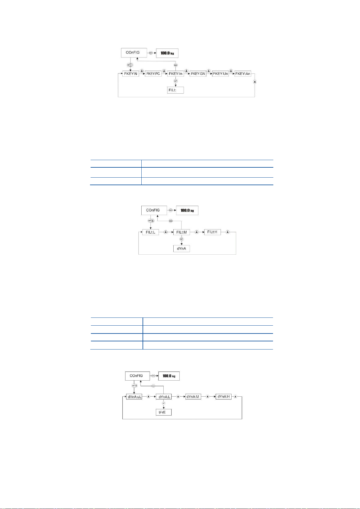
Press Enter key 3 times in Configuration menu to access * key item.
Press Enter key to enter the next item or press Esc key to return to previous step after selecting *
key function by ▲ key.
F key usage
You can select this key function from the table below.
n
Disable.
PC
Piece count
In
Increased resolution
Gn
Temporary Gross indication in Net
Un
Unit change
An
Animal weighing
n
Disable.
1
Automatic power off after 1 minute.
2
Automatic power off after 2 minutes.
3
Automatic power off after 3 minutes.
4
Automatic power off after 4 minutes.
5
Automatic power off after 5 minutes.
Page 24
FT-107 Weighing Terminal, Technical Manual, Rev. 1.0.0, August 2019 Page 24 of 46
Press Enter key 4 times in Configuration menu to access F key item.
Press Enter key to enter the next item or press Esc key to return to the previous step after selecting
F key function by ▲ key.
Stability Filter
You can change the digital filtering in this parameter to compensate the environmental effects on the scale
performance or for faster response.
L
Faster response with low filtering
M
Medium settling time (recommended)
H
Slow response with high filtering
Press Enter key 5 times in Configuration menu to access filter adjustment.
Press Enter key to enter the next item or press Esc key to return to the previous step after selecting
digital filtering by ▲ key.
Animal Filter
You can change the dynamic filtering in this parameter to compensate the animal movement on the scale.
Higher filtering gives more reliable result for very dynamic loads.
uL
Very Low filtering (1.6 second)
L
Low filtering (3.2 second)
M
Medium filtering (4.8 second)
H
High filtering (6,4 second)
Press Enter key 6 times in Configuration menu to access dynamic filter adjustment.
Press Enter key to enter the next item or press Esc key to return to the previous step after selecting
dynamic filtering for animal weighing by ▲ key.
Page 25
FT-107 Weighing Terminal, Technical Manual, Rev. 1.0.0, August 2019 Page 25 of 46
Tare
Taring feature of the scale can be programmed in this parameter for taring with key or auto taring
N
Disable
MT
Multi tare.
TC
Tare – Clear in sequence
AU
Automatic tare
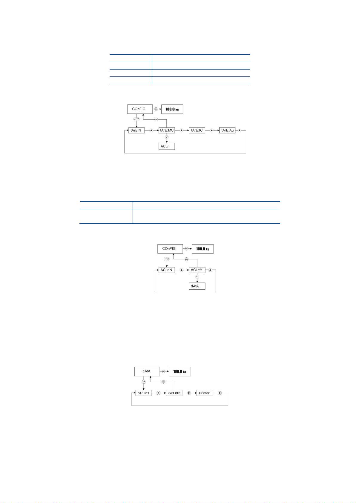
Press Enter key 7 times in Configuration menu to access taring function adjustment.
Press Enter key to enter the next item or press Esc key to return to the previous step after selecting
taring function of the scale by ▲ key.
Auto Clear Tare
This feature of the scale can be programmed in this parameter for auto clear tare.
N
Disable (default)
Y
The scale gets back to gross mode after unloading.
Press Enter key 8 times in Configuration menu to access this function adjustment.
Press Enter key to enter the next item or press Esc key to return to the previous step after selecting
this function of the scale by ▲ key.
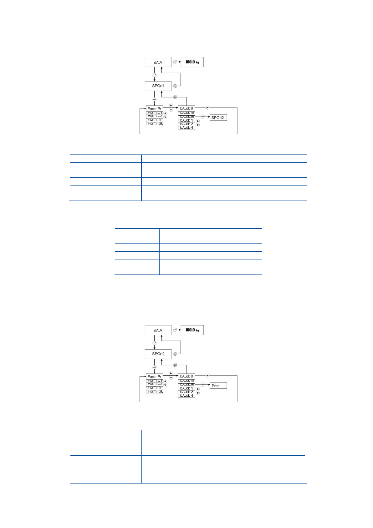
5.2.8 Serial Data Outputs:
To access the Data Outputs menu, press ADV key longer than one second until [ PLUPrO ] message
appears on the display. Press ► key several times until [ dAtA ] prompt appears. Serial data output and
printer data formatting related parameters are in this menu.
Press Enter key to enter the Serial port-1 setting or press ► key to access other menus.
Page 26
FT-107 Weighing Terminal, Technical Manual, Rev. 1.0.0, August 2019 Page 26 of 46
Serial Port-1 settings
To change Serial port-1 settings, press Enter key at [ SPOrt1 ] message.
The first step is the data format. The display indicates two digits at the right of the data format.
n
Disable
C1
Continuous-1 Page 43
(select for remote display connection)
C2
Continuous-2 (for PC) Page 43
Pr
Printer
SL
Single line printer (for PC)
After changing the data format with ▲ key, press Enter key to enter the next step, baud rate
adjustment. Two digits on the right of the display indicates the baud rate as;
01
1200 bauds
02
2400 bauds
04
4800 bauds
09
9600 bauds
19
19200 bauds
38
38400 bauds
Press Enter key to enter the next item or press Esc key to return to the previous step after selecting
baud rate by ▲ key.
Serial Port-2 settings (option)
To change Serial port-2 settings, press Enter key at [ SPOrt2 ] message.
The first step is the data format. The display indicates two digits at the right the data format.
n
Disable
C1
Continuous-1 (Page 43)
(select for remote display connection)
C2
Continuous-2 (for PC) (Page 43)
Pr
Printer
SL
Single line printer (for PC)
Page 27
FT-107 Weighing Terminal, Technical Manual, Rev. 1.0.0, August 2019 Page 27 of 46
After changing the data format with ▲ key, press Enter key to enter the next step, baud rate
adjustment. Two digits on the right of the display indicates the baud rate as;
01
1200 bauds
02
2400 bauds
04
4800 bauds
09
9600 bauds
19
19200 bauds
38
38400 bauds
Press Enter key to enter the next following item or press Esc key to return to the previous step after
selecting baud rate by ▲ key.
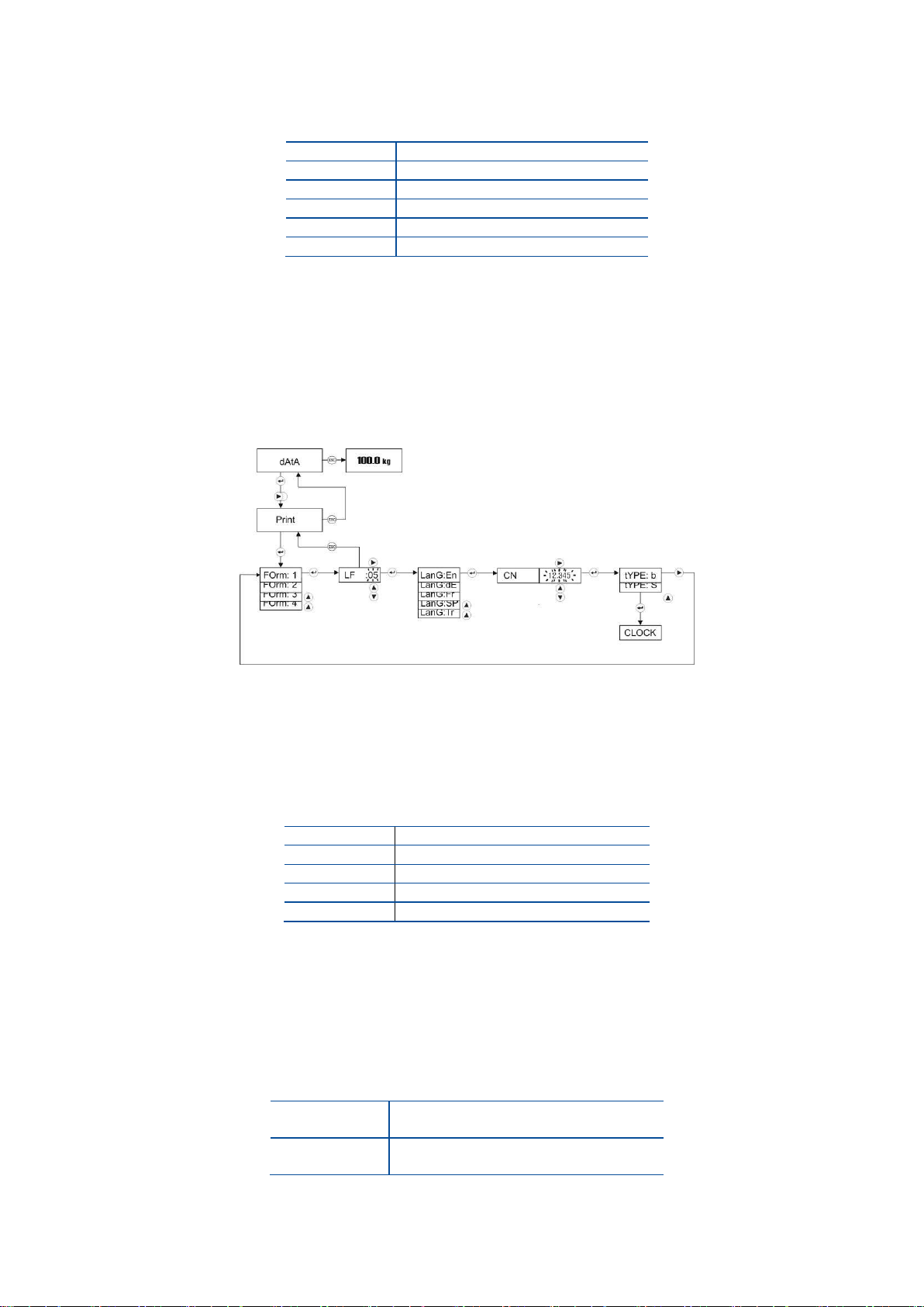
5.2.9 Printer setting
Press ► key several times until printer item seen.
The first item of printer setting is the printout format. Printer data output can be set to 4 different print form.
The printout form differs also with operation mode as described on Page 18. Select the printout format
from this table.
Select the format by pressing the ▲ key and press the Enter key to enter the next item, line feed.
After changing LF item with navigation keys for feeding the printout from printer, press Enter key.
The language selection item appears.
EN
English
DE
German
FR
French
SP
Spanish
TR
Turkish
Press Enter key to enter the next item or press Esc key to return to the previous step after printout
language setting.
[ CN ] Weighing Ticket Number
Press Enter key at [ CN ] prompt to adjust the printing number in this item. CN number can be reentered by pressing navigation keys. If the number exceeds 999999, it automatically returns to 1.
[ tyPE: S ] Printer Type
S
Print-out for narrow printers.
Maximum 16 characters per line.
B
Print-out for wide printers.
Maximum 26 characters per line.
After changing the printer type with ▲ key, press Enter key to enter the next item.
Page 28
FT-107 Weighing Terminal, Technical Manual, Rev. 1.0.0, August 2019 Page 28 of 46
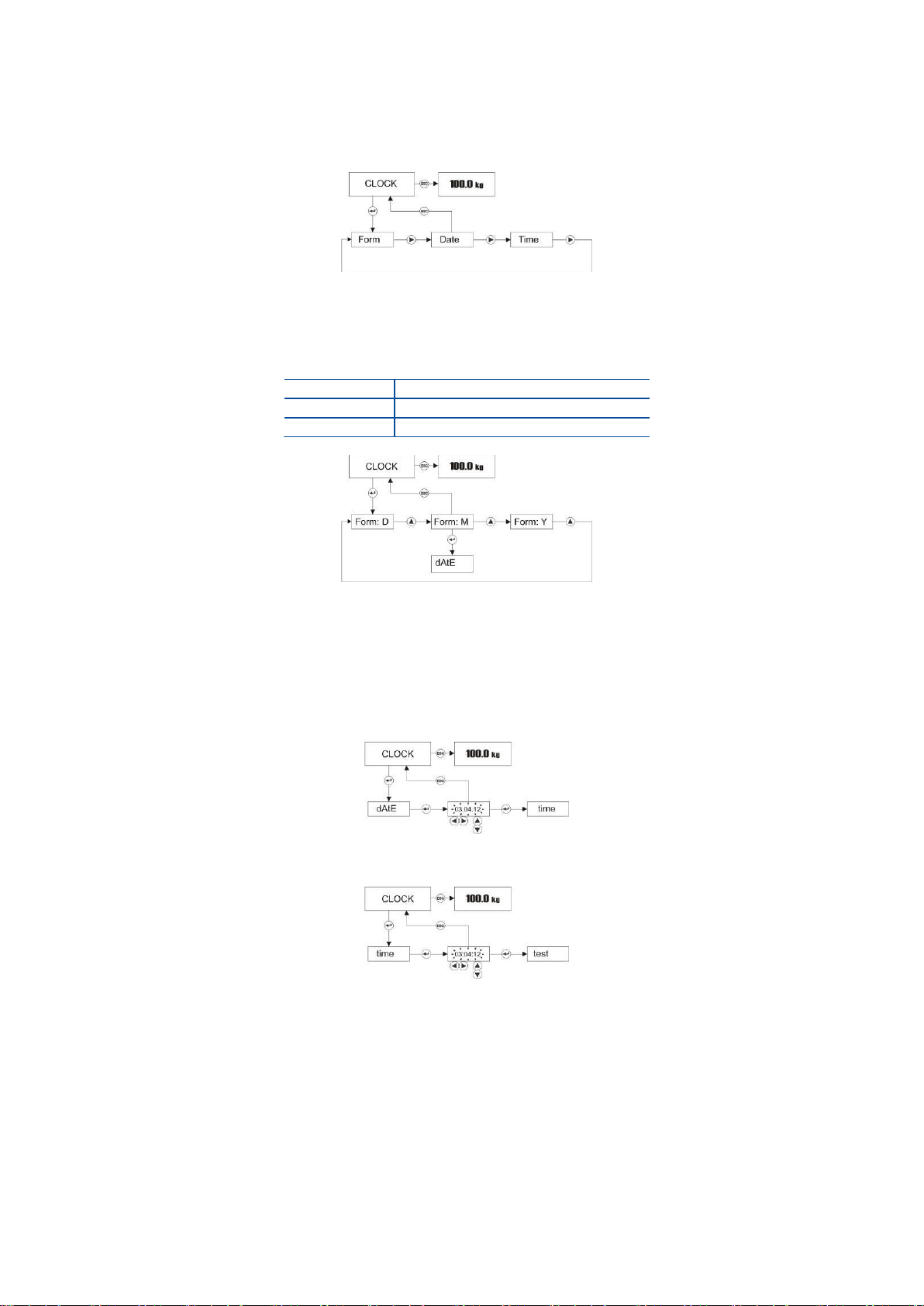
5.2.10 Date and Time
To access the Clock menu, press ADV key longer than one second until [ PLUPrO ] message appears on
the display. Press ► key several times until [ CLoCk ] prompt appears. Clock related items are in this menu.
Press Enter key to enter the Date format item or press ► key to access other items.
Date Format
Press Enter key at [ CLoCk ] prompt to adjust the date format for your country in this item.
d
DD:MM:YY
M
MM:DD:YY
Y
YY:MM:DD
Press Enter key to enter the next item or press Esc key to return to the previous step after date
format setting by pressing ▲ key.
Date
Press Enter key several times in clock menu until the date prompt seen. You can change the date as
shown below by navigation keys.
Press Enter key to access time adjustment.
Press Enter key to enter the next item or press Esc key to return to the previous step after time
adjustment with navigation keys.
Test Menu:
Test menu helps the service technician to find the problem source faster.
iCount
iCount is a value related with the ADC conversion to help the service engineer to follow the scale
performance in high resolution without dead load compensation.
Press Esc key to return to [ tESt ] menu. To return to the operation, press the Esc key for the
second time.
Page 29
FT-107 Weighing Terminal, Technical Manual, Rev. 1.0.0, August 2019 Page 29 of 46
5.3 Unit Change
You may need to change the unit in your application. One of the function keys should be programmed to Unit
change function to use this feature. The changeable units are between kg and lb or between g and oz.
1. The weight indication is in power on unit after power on.
2. Press the function key programmed for unit change (Page 23).
3. The indicator switches the unit to the second unit.
4. Press the same function key second time to go back to the first unit.
Warning:
1. The PLU memory and CLU memory data entries should be done in power on unit.
2. Unit change feature is not available after sealing the instrument in legal usage.
6. APPLICATION WEIGHING
6.1 Piece Counting
FT-107 indicator has several powerful features in count weighing as described in this section. It is
recommended to use the * key for piece counting (Page 23).
Press * key to enter piece counting operation. The last used average piece weight (APW) value is valid in
counting. APW default is the increment of the scale at power on.
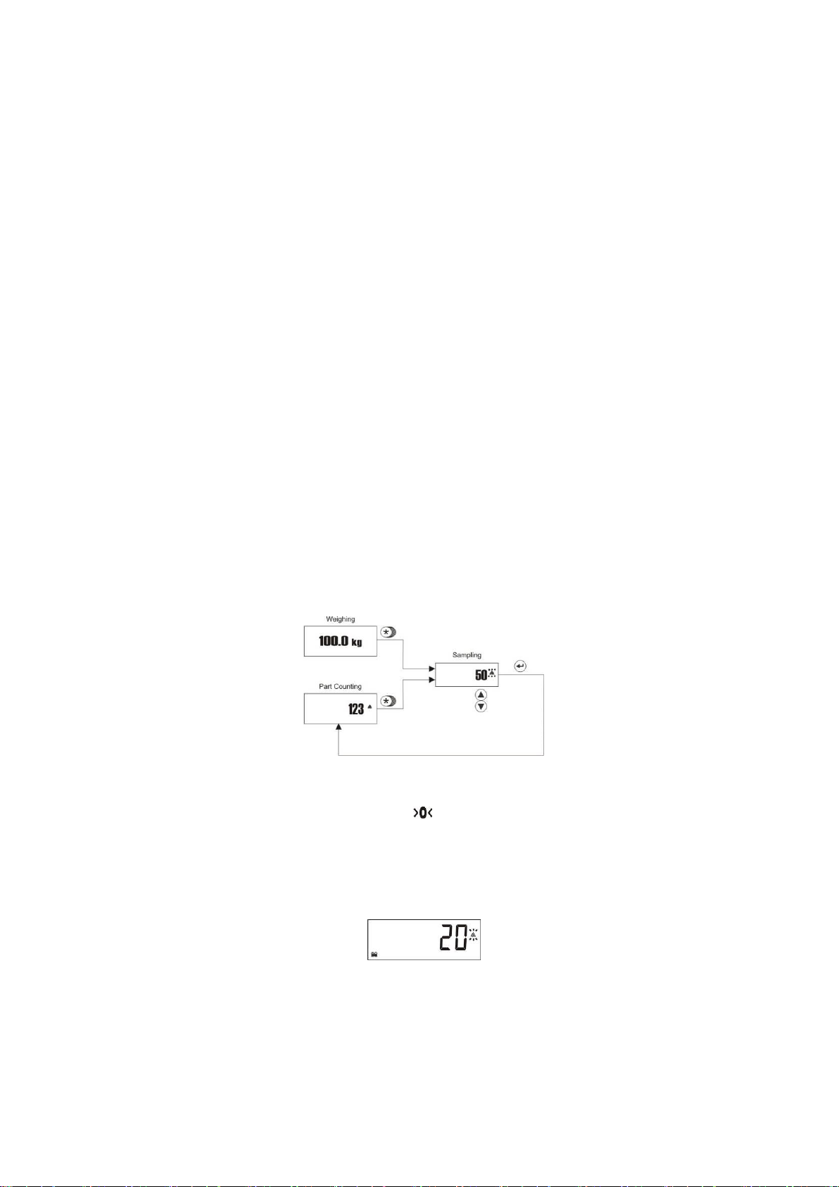
Sampling
The scale counts the pieces on it by using the calculated average piece weight (APW) of the item. In
sampling, FT-107 measures a certain number of pieces total weight in very high resolution and divides it by
the number of pieces (the so-called sampling quantity) to find average piece weight (APW). Based on this
calculated average piece weight, counting can then be carried out.
Sampling should be done very carefully for correct counting.
1. Empty the scale and press Zero key until symbol appears on the display.
2. Press * key longer than a second until [ 10] or any other reference number of pieces appears on
the display. This value is the quantity of pieces you can place on the platform for sampling.
3. If the pieces are small or piece weights are not very close to each other, sampling in high quantity is
recommended to increase the counting accuracy. Press ▲ to change the sampling quantity to 20,
30, 50 or 100. To decrease the quantity press ▼ key.
4. Once the exactly counted quantity is placed on the platform, press Enter key.
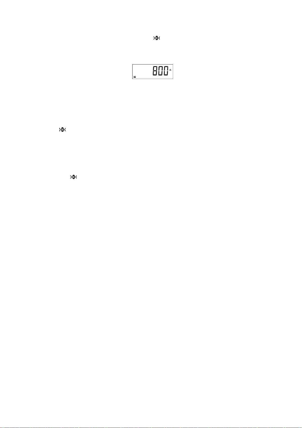
5. Display will stop flashing after sampling and start to display the quantity on the scale.
Page 30
FT-107 Weighing Terminal, Technical Manual, Rev. 1.0.0, August 2019 Page 30 of 46
Counting without container
1. After sampling press the Zero key, the sign appears.
Or call the APW of the item from CLU memory (Page 19).
2. Place the pieces you want to count on the weighing pan,
3. The total quantity of pieces will be displayed.
If you want to accumulate the sequential counting, press M+ key (Page 30).
To return to the weighing mode, press * key. The last used APW can be used at the following piece counting
at the following piece counting.
Counting pieces into a container
1. For counting into a container, place an empty container on the scale and tare with the Tare key (the
sign appears on the display).
2. If needed, perform sampling into the container after taring.
3. Add parts into the container to count them.
Note: If the automatic taring function is active, you do not need to press the Tare key, because the
scale will be tarred automatically as soon as the container was placed on the weighing pan.
Counting pieces out of a container
1. Place the full container on the weighing pan and then press the Tare key to tare the scale
(the sign appears).
2. Press the * key to enter to the piece counting mode.
3. If needed, perform sampling as
a. Press the * key longer than one second until sampling quantity appears.
b. Change the sampling quantity by pressing ▲ or ▼ keys.
c. Remove the sampling quantity of pieces from the weighing container and then press the
Enter key for sampling.
d. The scale starts to count by displaying the number of pieces after sampling by a minus sign.
Or select the item APW from CLU memory (Page 19).
4. Take some pieces out of the container.
5. The scale displays the number of removed pieces showing the minus sign.
6. Press Tare key for next counting.
Press * key to return to basic weighing operation.
APW optimization
Sampling in high quantity gives higher accuracy result although the high quantity is more difficult to count by
hand.
You may follow the procedure below for APW optimization:
1. First count low quantity, for example 10 pcs and do sampling with 10 pcs.
2. Then count on the scale 2 times of the sampled quantity. In our example count 20 pcs on the scale
and apply sampling for 20 pcs.
3. Then count 50 pcs on the scale and perform sampling with 50 pcs.
4. Then you may count 100 pcs on the scale and may perform sampling with 100 pcs.
After each APW optimization, piece counting accuracy will increase.
Total memory at counting
The quantities of the sequential counting can be accumulated in as total value in the piece counting
accumulator (CAD).
1. For counting accumulation, press M+ key during the quantity is displayed and the scale stable. The
accumulation number appears on the display as [ Cad001 ].
2. Place another batch on the scale and press M+ key again to add the second counting number to
total [ Cad002 ].
3. Continue adding further pieces to the memory by pressing M+ key.
Page 31
FT-107 Weighing Terminal, Technical Manual, Rev. 1.0.0, August 2019 Page 31 of 46
The accumulated total count can be retrieved pressing MR key.
While the total count is displayed it can be printed by pressing the Enter key.
To delete the accumulated value, press MC key during count accumulation is displayed.
APW Recording to the memory after sampling
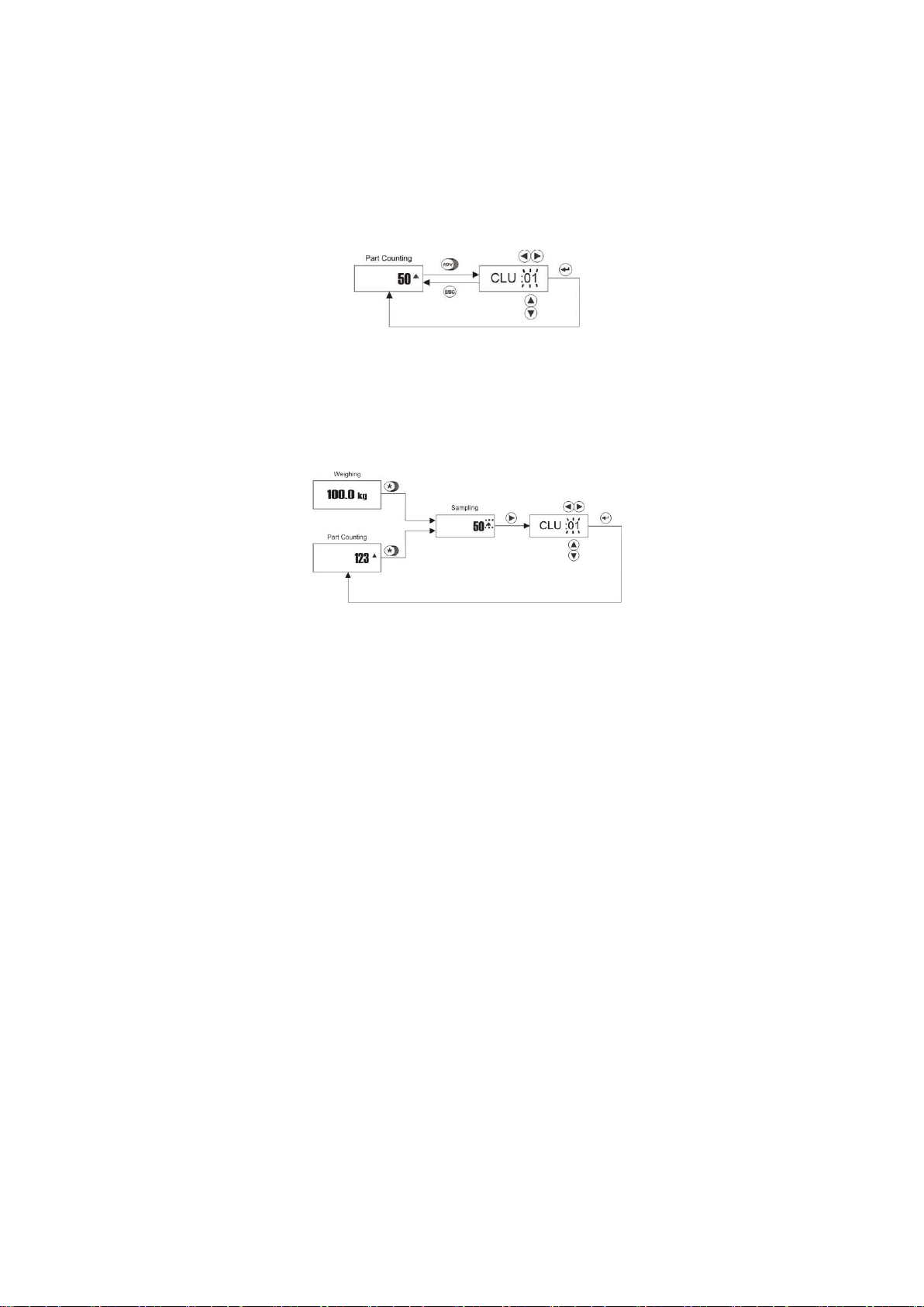
Up to 100 average piece weights APW of the different materials can be saved in the CLU memory. For saving
of APW into the CLU memory, press ADV key in piece counting mode longer than one second
Press ▲ and ▼ keys to increase / decrease the flashing digit. Press ► and ◄ to shift to the next digit..
After accessing the desired memory code, press Enter key for saving. The indicator returns to the counting
operation automatically.
Counting with preset APW record
To access to memory database press * key longer in counting mode or in weighing mode and then ► key.
Press Enter key after accessing the CLU memory code with navigation keys.
Page 32
FT-107 Weighing Terminal, Technical Manual, Rev. 1.0.0, August 2019 Page 32 of 46
6.2 Checkweighing (+/-)
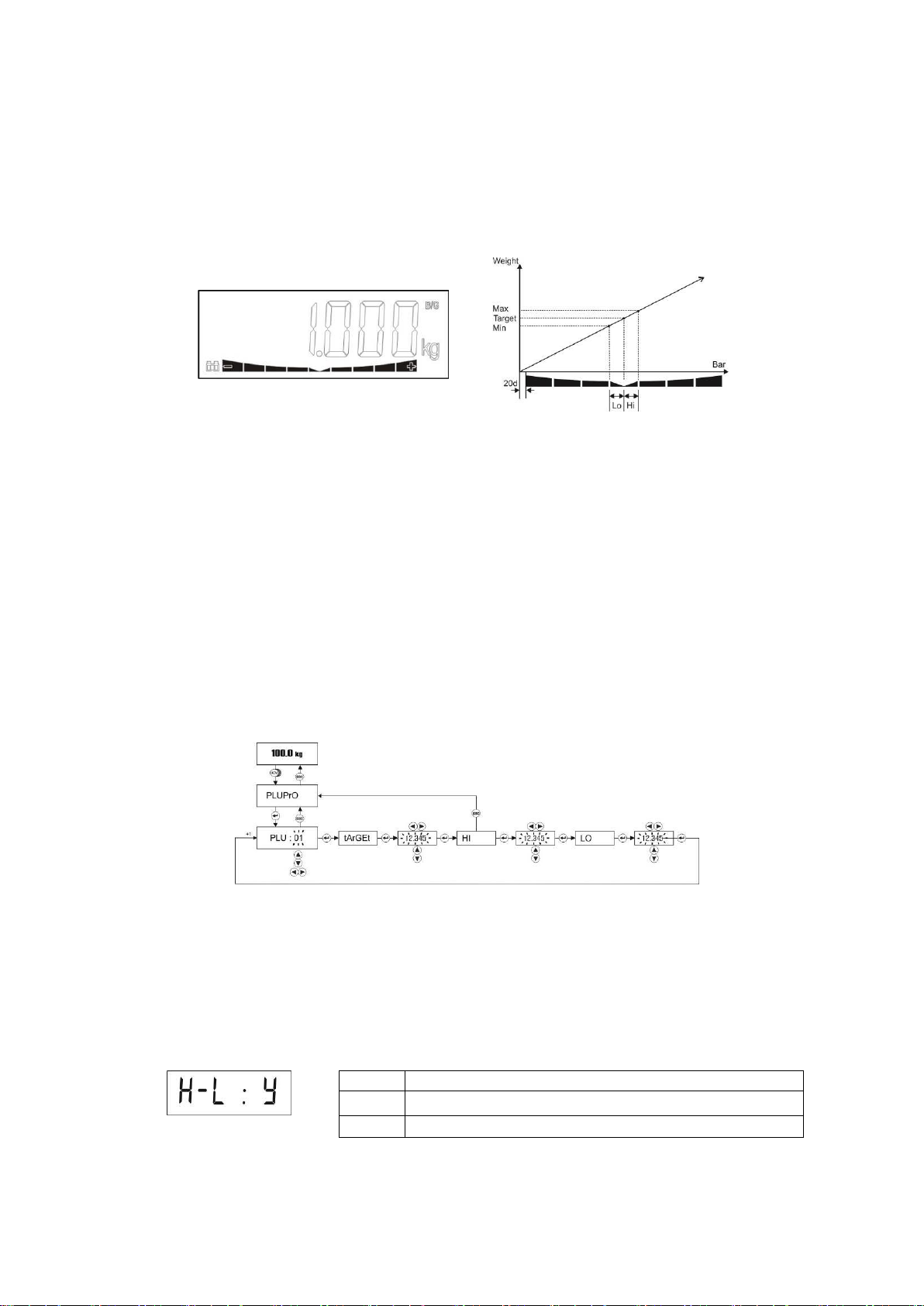
This function is used for classifying products. The check weighing bar on the bottom of the display helps the
operator to indicate the deviation from target weight. In the Figure 6.1 the bar indicates the status of the
tolerance during the check weighing. The indicator is also programmable for acoustic check weighing warning
(Page 20).
Check weighing operation requires the nominal weight and tolerance values entry into the PLU memory.
Figure 6.1 – Check weighing bar
Data entry to Checkweighing memory PLU and Checking in quantity memory ALU
Warning: The PLU memory data entries are done in power on unit.
In Checkweighing mode, FT-107 offers PLU storage space for 100 different materials and in Piece counting
100 ALU storage space for checking in quantity.
For data entries to the PLU / ALU memory press ADV key longer than one second in Advanced function.
Follow the diagram below to entry the data into the PLU or ALU memory. Here, the Target is the nominal value
of the material. Hi and LO are the “+ tolerance” and “– tolerance” of the material in sequence.
For example, if the target is 1000 g and the weight limits are 950 and 1100 g in checkweighing enter:
Target = 1000 g, Hi = 100 g and Lo = 50 g.
The values are entered in quantity to the ALU memory entry.
PLU / ALU code increases or decreases by pressing ▲ or ▼ keys. The values for Target, Hi and Lo are
selected by pressing ► or ◄ keys.
Checkweighing operation (+/-)
Checkweighing is used to check if the weight of an object is in tolerance. The back-light color changes
automatically to indicate if the load is under, over or in tolerance. Refer to page 22 to adjust this feature.
1. Press H-L key longer than one second until the message H-L : Y appears.. The letter on the right
indicates the check weighing is enabled or not.
2. To enable the checkweighing operation, press ▲ key, select “ Y “ and then press Enter key.
3. The PLU memory number appears on the display as [ PLU :01 ]
4. Change the PLU record number by using navigation keys and press the Enter key to start operation
or press Esc key to return to operation without saving the PLU code.
5. The Target, Hi and Lo values display automatically before checkweighing operation.
n
Checkweighing disabled
Y
Checkweighing enabled
t
Checkweighing enabled with auto tare in okay range
Page 33
FT-107 Weighing Terminal, Technical Manual, Rev. 1.0.0, August 2019 Page 33 of 46
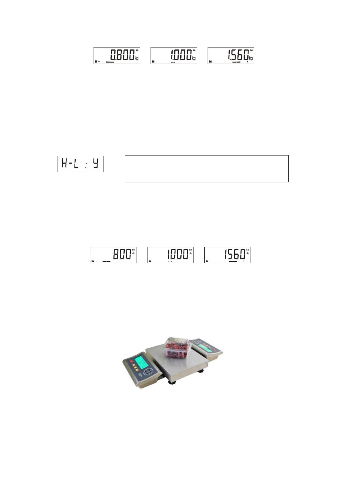
6. Place an object on the platform and the checkweighing bar is activated after loading the platform as
shown below.
Under
In tolerance
Over
To return from checkweighing function to basic weighing, press H-L key for a while, change the H-L item
value to “n” and press Enter key. The checkweighing bar will be disabled.
Checking the quantity at piece counting (+/-)
This feature is used for checking if the quantity is in tolerance at piece counting mode. The back-light color
changes automatically if weighing to indicate the load is under, okay or over. Refer to page 22 to adjust this
feature.
1. Press H-L key longer than one second in piece counting mode until the message below appears.
The letter on the right indicates the check weighing is enabled or not.
2. To enable the checking operation, press ▲ key, select “ Y “ and then press Enter key.
3. The ALU memory number appears on the display as [ ALU :01 ]
4. Change the ALU record number by using navigation keys and press the Enter key to start operation
or press Esc key to return to the operation without saving the ALU code.
5. The values Target, Hi and Lo display automatically before check piece operation.
6. Place an object on the platform and the check piece bar is activated after loading the platform as
shown below.
Under
In tolerance
Over
To disable from checkingweighing function, press H-L key for a while, change the H-L item value to “n” and
press Enter key.
Double sided display scale for multi operator
FT-107(S) can be programmed as “Remote” instrument and then connected to the weighing indicator over
RS232 port. Double sided display / keypad scale can be configured by using a weighing scale and a remote
instrument.
n
Check quantity disabled
Y
Check quantity enabled
t
Check weighing enabled with auto tare in okay range
Page 34
FT-107 Weighing Terminal, Technical Manual, Rev. 1.0.0, August 2019 Page 34 of 46
6.3 Animal Weighing
One of the function keys (the * key is recommended) can be programmed for animal weighing. The indicator
calculates the weight of the dynamic load after pressing the programmed function key. The dynamic filter value
must be adjusted according to the application to achieve the best results. The dynamic weighing cycle is;
1. Load the scale.
2. Press the * key (if the function key was programmed for animal weighing (Page 23))
3. The message [ - - - - - ] appears to indicate that the indicator is measuring the dynamic weight.
4. After calculating the dynamic weight, the indicator displays the weight value.
5. Press Enter key to print out or M+ key to add the weight value to the total memory.
6. Unload the scale or press Esc key to return to the basic weighing mode.
6.4 Temporary Gross Weight Indication
Sometimes it is needed to check shortly the gross weight value during net weighing operation. If one of the
function keys is programmed to G/N function (Page 23), temporary gross weight value indication is available in
net operation.
1. Press the G/N programmed function key in net mode.
2. The indicator activates the and signs and indicates the gross weight value.
3. The display goes back to the net weight indication after 5 seconds automatically.
Page 35
FT-107 Weighing Terminal, Technical Manual, Rev. 1.0.0, August 2019 Page 35 of 46
7. PROGRAMMING AND CALIBRATION
You will find the programming and calibration procedure of FT-107 weighing terminal in this section.
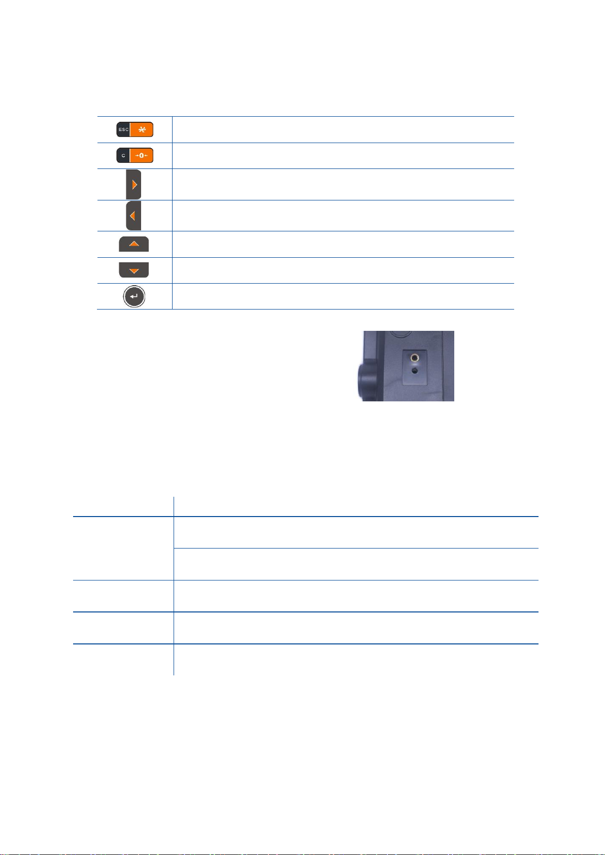
Escape key
:
- Return to the menu
- Return to the operation without saving parameters.
Zero key
:
Fast calibration access.
Right key
:
- Next menu item.
- Move to the right digit.
Left key
:
- Previous menu item.
- Move to the left digit.
Up key
:
Increase the selected digit value.
Down key
:
Decrease the selected digit value.
Enter key
:
Press this key to go to the next item.
Calibration switch is located on the rear of the
instrument. The calibration switch should be
sealed before putting the scale in to usage.
Figure 7.1- The location of calibration switch
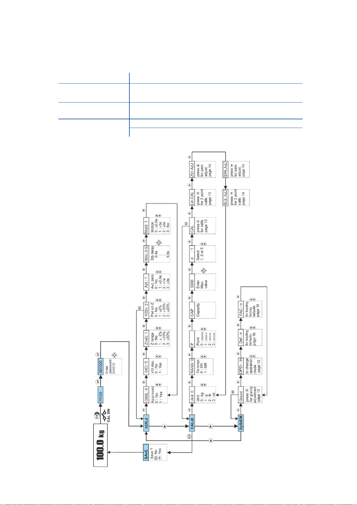
7.1 Entering the Programming and Calibration
To enter the programming menu, you should follow the description in the table below.
Display
Operation
[ 123.456 ] kg
Press STP key until [ PASS ] prompt appears and then Enter key (only
non-OIML scales ).
Or press calibration switch.
[ PASS ]
Enter ‘011012’ with navigation keys.
[ 011012 ]
Press Enter key for confirm password.
[ bUıLd ]
First block of set-up.
Set-up menu consist of three main blocks, which are Scale build block, Calibration block and System block.
Press ► key to reach the desired block and press Enter key. Press Enter key to navigate in this block
items or change item value by ▲ and ▼ keys. For entering numerical value, press the ► and ◄
keys to select the digit and press the ▲ and ▼ keys the change the value.
Page 36
FT-107 Weighing Terminal, Technical Manual, Rev. 1.0.0, August 2019 Page 36 of 46
7.2 Exiting the Programming and Calibration
With the Esc key the menu block can be left. Follow the diagram below to return to the operation from setup.
Display
Operation
[ item ]
For example [ ZrnG ]
Press Esc key to return to the main block.
[ block ]
For example [ bUıLd ]
Press Esc key to leave the set-up.
[ SAVE ]
Press Enter key to save the set-up.
Press Esc key to return to operation without saving.
Page 37

FT-107 Weighing Terminal, Technical Manual, Rev. 1.0.0, August 2019 Page 37 of 46
7.3 Fast Access to the Calibration
The instrument has fast access calibration feature to save time for the service technician. If only the calibration
adjustment is needed, follow the steps below for fast calibration.
Display
Operation
[123.456 ] kg
Press STP key until [ PASS ] prompt appears and
confirm with Enter (only non-OIML scales ).
Or press calibration switch.
[ PASS ]
Enter “011012” with navigation keys.
[ 011012 ]
Press Enter key for confirm password.
[ bUıLd ]
First block of set-up. Press Zero key longer than 2 seconds to
jump to the zero adjustment until the prompt on the below seen.
[ CAL ]
Zero adjustment: Unload the scale and press Enter key. Do not
touch the scale at [ - - - ] prompt.
[ LoAd ]
[ XXXXX ]
Span adjustment: Load the scale and enter the load value by
pressing navigation keys and press Enter key. Do not touch the
scale at [ - - - ] prompt.
[ LınCAL ]
The next item Linearity Correction prompt appears after the
calibration.
Page 38
FT-107 Weighing Terminal, Technical Manual, Rev. 1.0.0, August 2019 Page 38 of 46
7.4 Programming and Parameters
[ Build ] Scale Build Block
The scale is defined with the following parameters. Press Enter key to enter the block or press ► key to
enter the next block or press Esc key to return to the operation (Page 36 ).
7.4.1 [ OIML: 0 ] OIML
O
Non-OIML scale application.
1
Approved scale.
This parameter should be selected as ‘ 1 ’ for approved scales to activate the calibration switch for
securing the sealing.
Press ▲ key to change the value. Press Enter key to enter the next item or press
Esc key to return to the main block.
7.4.2 [ InCr : 0 ] Increased Display Resolution
O
Weight indication.
1
x10 times increased resolution.
Press ▲ key to change the value. Press Enter key to enter the next item or press
Esc key to return to the main block.
7.4.3 [ ZrnG: 1 ] Zero Range
This parameter sets the zeroing range by pressing the Zero key.
O
Disable
1
±2% of the scale range
2
±10% of the scale range
3
±50% of the scale range
Press ▲ key to change the value. Press Enter key to enter the next item or press
Esc key to return to the main block.
7.4.4 [ PZer: 1 ] Power on Zero Range
This parameter sets the zeroing range at power on.
O
Disable
1
±2% of the scale range
([E E E] prompt cannot be erased. Call service)
2
±10% of the scale range
3
±20% of the scale range
Press ▲ key to change the value. Press Enter key to enter the next item or press
Esc key to return to the main block.
7.4.5 [ AZT : 1 ] Automatic Zero Tracking
This parameter sets the AZT against small zero drifts against environmental affects like rain, snowing
and dust etc.
O
Disable
1
±0.5 e
2
±1 e
3
±3 e
Press ▲ key to change the value. Press Enter key to enter to next item or press
Esc key to return to the main block.
Page 39

FT-107 Weighing Terminal, Technical Manual, Rev. 1.0.0, August 2019 Page 39 of 46
7.4.6 [ StbL: 0.5 ] Stability Delay
If the scale is stabile during this time zeroing, taring, printing etc. functions can be proceeded. The
stability time can be entered between 0,4 and 9,9 seconds.
Press ▲ key to change the value. Press Enter key to enter the next item or press
Esc key to return to the main block.
7.4.7 [ Motd: 1 ] Motion Detection
This parameter sets the stability range as;
O
± 0.5 e
1
± 1 e
2
± 2 e
3
Disable
Press ▲ key to change the value. Press Enter key to enter the next item or press
Esc key to return to the main block.
Page 40

FT-107 Weighing Terminal, Technical Manual, Rev. 1.0.0, August 2019 Page 40 of 46
7.5 Calibration
Please read this document carefully and select the parameter values which will fit your application before
programming the instrument
Warning: You cannot change the legally related parameter values and calibration after sealing the
instrument in legal usage. Be sure the proper adjustments you done before sealing the scale.
Before the calibration can be performed the capacity and resolution of the scale must be defined.
Calibration involves emptying the scale then placing a known test weight on an empty platform and allowing
the indicator to capture values for zero and span. Calibration is performed as;
7.5.1 [ CALıB ] Scale Parameters
You can reach the parameters to calibrate the scale in this block. Press Enter key to enter to this block or
press ► key to enter the next block or press Esc key to return to the operation (Page 36).
[ Unit: 0 ] Unit
O
kg 1 g 2 lb 3 oz
Press ▲ key to change the value. Press Enter key to enter the next item or press
Esc key to return to the main block.
[ rAnG: 0 ] Operation Range
O
Single range
1
Multi range
Press ▲ key to change the value. Press Enter key to enter the next item or press
Esc key to return to the main block.
[ P : 0 ] Decimal Point
O
XXXXXX
1
XXXXX.X
2
XXXX.XX
3
XXX.XXX
4
XX.XXXX
5
X.XXXXX
Press ▲ key to change the value. Press Enter key to enter the next item or press
Esc key to return to the main block.
If the scale is a multi-range scale two capacities and divisions, Cap1 / d1 and Cap2 / d2 will be shown
instead of single range CAP / d.
[ CAP ] Capacity
Press Enter key and enter the first scale range capacity by pressing navigation keys. Press
Enter to enter the next item. Maximum value can be 15000 kg or 30000 lb.
[ d : 1 ] Division
Select the first division of the scale from available ranges by pressing navigation keys.
Press Enter to go to the next item.
Page 41

FT-107 Weighing Terminal, Technical Manual, Rev. 1.0.0, August 2019 Page 41 of 46
7.5.2 [ CAL ] Calibration
Calibration consists of two adjustments: zero adjustment and span adjustment.
For linearization of a scale press ► key.
Calibration is performed as;
1. Press Enter to start the calibration.
2. At the [ UnLoAd ] prompt, unload the scale then press Enter .
3. The indicator automatically starts to capture zero and the [ - - - ] message indicates the operation
is in progress.
4. After a while the [ LoAd ] prompt appears with a suggested test weight on the display as
[ XXXXXX ]. For definition of different test weight use the navigation keys.
FLINTEC recommends using between 50 and 100% of the scale capacity but minimum 20%.
An insufficient weight leads to a calibration error.
5. Place the test weights or another practical weight on the scale.
6. Press Enter to start span calibration. [ - - - ] message appears on the display while span
calibration is being performed.
7. After the calibration the Linearity Correction can be executed.
7.5.3 [ LınCAL ] Linearity Correction
Three steps calibration will improve the performance of the scale.
If you will not perform linearity correction press ► key or press Esc key to return to the main
block.
Linearity correction is performed as;
1. Press Enter prompt to start three-point calibration.
2. At the [ UnLoAd ] prompt, remove any weight on the platform, then press Enter .
3. The indicator automatically starts to capture zero and the [ - - - ] message indicates the operation
is in progress.
4. After a while the [ Load 1 ] prompt appears with a suggested test weight on the display as
[ XXXXXX ]. This load shall be between 35% and 65% of the scale’s capacity. Enter the Load 1
value using navigation keys.
5. Load the scale.
6. Press Enter to start the span calibration at Load 1. [ - - - ] message indicates the operation is in
progress.
7. At the [ Load 2 ] prompt, the second load will be suggested as [ XXXXXX ]. For definition of
different test weight use the navigation keys. Load 2 weight shall be between 90% and 100% of
the scale capacity.
8. Place the test weights or another practical weight on the scale.
9. Press Enter to start second step span calibration. [ - - - ] message appears on the display.
10. The next item Zero Adjustment prompt appears after the linearization.
7.5.4 Zero and Span Adjustment
[ ZerAdJ ] Zero Adjustment
This parameter is only being used for refreshing the zero level of the scale to prevent wrong weighing
from zero drifts.
If you will not perform Zero adjustment press ► key or press Esc key to return to the main block.
Zero adjustment is performed as;
1. Press Enter key to start the zero adjustment.
2. At the [ UnLoAd ] prompt, remove any weight from the platform, then press Enter .
3. The indicator automatically starts to capture zero and the [ - - - ] message indicates the operation
is in progress.
4. Next item appears on the display after the zero adjustment.
Page 42

FT-107 Weighing Terminal, Technical Manual, Rev. 1.0.0, August 2019 Page 42 of 46
[ SPA.AdJ ] Span Adjustment
This parameter lets you to perform span adjustment.
If you will not perform Span adjustment press ► key or press Esc key to return to the main block.
Span adjustment is performed as;
1. Press Enter key to start the span adjustment.
2. After a while the [ LoAd ] prompt appears with a suggested test weight on the display as
[ XXXXXX ]. For definition of different test weight use the navigation keys.
FLINTEC recommends to use between 50 and 100% of the scale capacity but minimum 20%.
An insufficient weight leads to a calibration error.
3. Place the test weights or another practical weight on the scale.
4. Press Enter to start span adjustment. [ - - - ] message will be shown on the display while span
calibration is being performed.
5. The next item Span Adjustment Under Load prompt appears after the calibration.
[ SUL.AdJ ] Span Adjustment Under Load
This parameter is being used to perform span adjustment of a scale without lifting the load. This
operation is especially recommended for span adjustment for filled tanks without emptying the
material.
If you will not perform Span Adjustment Under Load press ► key or press Esc key to return to
the main block.
Span Adjustment Under Load is performed as;
1. Press Enter key to start the span adjustment under load.
2. At the [ UnLoAd ] prompt, press Enter for temporary zero adjustment.
3. After a while the [ LoAd ] prompt appears with a suggested test weight on the display as
[ XXXXXX ]. For definition of different test weight use the navigation keys.
FLINTEC recommends to use between 50 and 100% of the scale capacity but minimum 20%.
An insufficient weight leads to a calibration error.
4. Place the test weights or another practical weight on the scale.
5. Press Enter to start span adjustment. [ - - - ] message will be shown on the display while span
calibration is being performed.
6. The next item appears after the calibration.
7.5.5 [ GrAvit ] Gravity Adjustment
For gravity adjustment before shipment of the scale, enter the values below.
If you will not adjust the gravity press ► key to enter the next item.
1. Press Enter key.
2. [ CAL-Gr ] Gravity of the manufacturer. Press Enter key and enter the gravity coefficient of the
place of the scale calibration via navigation keys. Press Enter key.
3. [ USAGE ] Gravity of the usage. Press Enter key and enter the gravity coefficient of the place of
the scale usage via navigation keys.
Warning: Check the scale accuracy after gravity adjustment against wrong entry.
Page 43
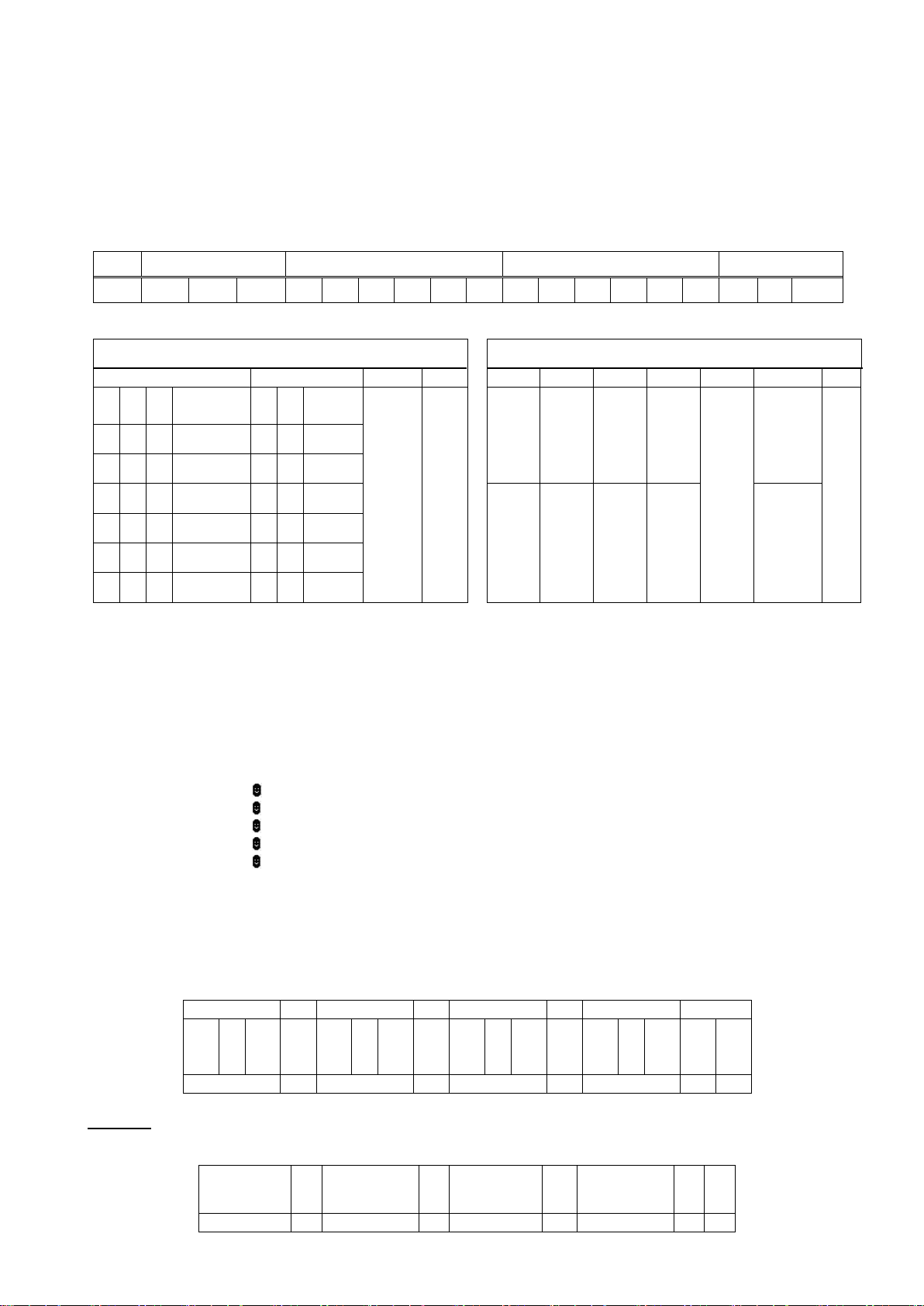
FT-107 Weighing Terminal, Technical Manual, Rev. 1.0.0, August 2019 Page 43 of 46
8. SERIAL DATA FORMATS
Continuous data and single line data format are described in this section. FT-107´s serial ports are suitable for
bi-directional communication. If you transmit ASCII codes for P(print), Z(zero), T(tare) or C(clear) to the one
of the serial ports, the indicator will act like the related keys are pressed.
Continuous-1 Data Format
The data format of the Continuous-1 data output:
Status
Indicated
Tare
STX
STA
STB
STC
D5
D4
D3
D2
D1
D0
D5
D4
D3
D2
D1
D0
CR
LF
CHK
The including of the status bytes STA, STB and STC are
Definition Table for Status A (STA)
Definition Table for Status B (STB)
Bits 0, 1 and 2
Bits 3 and 4
Bits 5,6
Bit 7
Bit 0
Bit 1
Bit 2
Bit 3
Bit 6
Bit 7
0 1 2
Decimal
point
3
4
Inc.
size
Always 1
X
1= Net 1= Weight negative
1= Error 1= Unstable
Always = 1
1=Zeroed with power on zero
X
1 0 0
XXXXXO
1 0 X 1 0 1 0 XXXXXX
0 1 X 2 1 1 0 XXXXX.X
1 1 X 5
0 = Gross 0 = Weight positive 0 = No Error 0 = Stable 0 = Not power on zeroed
0 0 1
XXXX.XX
1 0 1 XXX.XXX
0 1 1 XX.XXXX
Status C (STC) is always hex ‘30’.
Note: The weight data is represented with right aligned and the error messages (UNDER, OVER and A.OUT)
are represented with left aligned in indicated data field.
Continuous-2 Data Format
The data format of the Continuous-2 data output is;
[STX][STATUS][SIGN][INDICATED WEIGHT VALUE][UNIT][CR][LF][CHK]
Examples :
S+000123.4kg (weight is stable and 123.4)
D+000123.4kg (weight is dynamic and 123.4)
+ (Over load)
- (Under load)
O (ADC out error)
Checksum Calculation:
CHK (Checksum) = 0 – (STX + STATUS + ..... + LF)
Single Line Data Formats
Single line data output of the instrument is transmitted in the following data structure.
CN Gross
Tare
Net
MSD LSD
Spac
e
MSD LSD
Spac
e
MSD LSD
Spac
e
MSD LSD
LF
CR
9 chars
3
13 chars
3
13 chars
3
13 chars
1
1
Example:
Data output string for CN=21, Gross weight = 30.00 kg, Tare = 10.00kg and Net = 20.00kg will be;
CN: 21
G:
30.00kg
T:
1.000kg
N:
2.000kg
LF
CR
9 chars
3
13 chars
3
13 chars
3
13 chars
1
1
Page 44
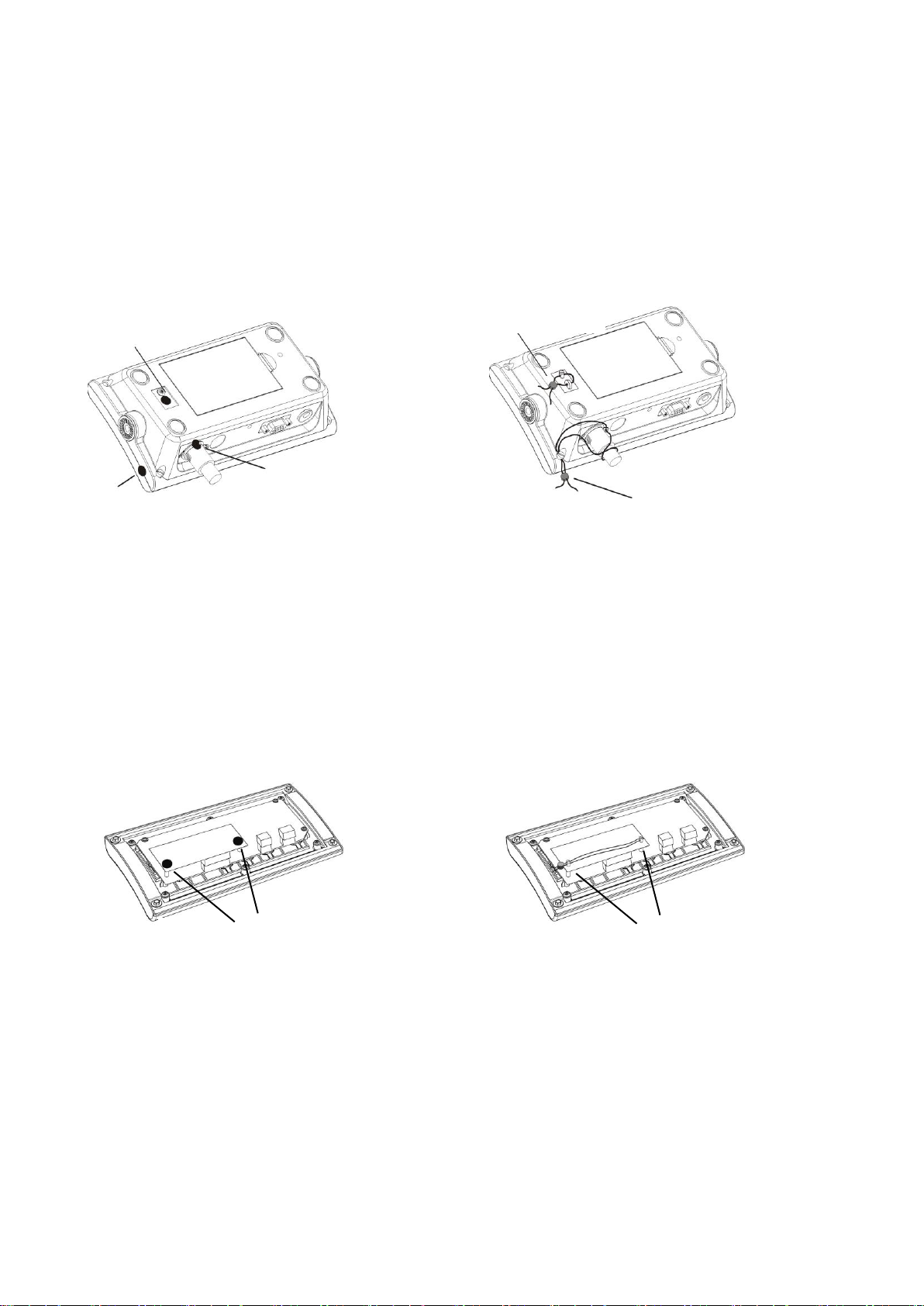
FT-107 Weighing Terminal, Technical Manual, Rev. 1.0.0, August 2019 Page 44 of 46
9. SEALING OF APPROVED SCALE
Sealing of FT-107
Sealing with sticker: Sealing with lead:
Sealing of FT-107S
Sealing with sticker: Sealing with lead:
Load cell connector and
calibration switch sealing
Load cell connector and
calibration switch sealing
Caliration switch
sealing
Load cell connector sealing
Housing sealing
Calibration switch
sealing
Load cell connector and
housing sealing
Page 45

FT-107 Weighing Terminal, Technical Manual, Rev. 1.0.0, August 2019 Page 45 of 46
10. TROUBLE SHOOTING
FT-107(S) weighing indicator had been designed as a very reliable and virtually error free instrument.
However, if an error occurs, do not attempt to repair the equipment before understanding what caused the
error. Note the problems you have with your instrument and the error messages shown on the display. Then
try to solve the problem according to the error table given below.
[ Over ] on the display
Load cell signal is higher than calibrated maximum level. Call
service for checking load cell and recalibration.
[ Under ] on the display
Load cell signal is lower than calibrated zero level. Call
service for checking load cell and recalibration.
[ E E E ] on the display
Zeroing at power on not possible. Check the scale.
The scale should be unloaded at power on.
[ AdCoUt ] on the display
Load cell signal is out of the ADC range.
- Check load cell connection.
- Check the load cell.
- Check the calibration.
- Change PCB.
Err 2
ADC communication error.
- Change PCB.
Err 34
Load cell signal is not increasing after loading the scale.
- Check the load cell connection.
- Check the load cell cable in the instrument.
- Change PCB.
Err 35
Load increase is small.
- Check the scale mechanic.
- Check the load cell connection.
- Increase the test weight.
- Change PCB.
Err 37
Scale is not stabile for calibration.
Err 70
Maximum scale capacity is more than 15000 kg or 30000 lbs.
- Reduce the capacity of the scale.
Err XX ( others )
- Disconnect power adaptor and battery.
- Connect battery and power adaptor in sequence
- Switch on the instrument if it is not.
- If there is any malfunction, change PCB or call service.
Page 46

www.flintec.com
 Loading...