

Page 1
Dual Electric Fan #262
Fits 1994-2002 Dodge 2500/3500 w/ 5.9L Cummins Diesel
INSTALLATION INSTRUCTIONS
REMOVE EXISTING FAN & SHROUD:
1. Disconnect battery negative (-) cable from both batteries.
2. Make sure the engine is cool! Open the radiator cap slightly to release the
vacuum. Using the radiator valve drain located on the driver’s side, drain
enough coolant to clear the upper inlet hose of coolant. A hose or funnel will
help reduce spillage.
3. Using a 10mm socket or wrench, remove secondary battery positive (+)
cable that runs along the top of the radiator. FOR YOUR SAFETY, discon-
nect cable completely from both batteries!! see detail 1.
4. Disconnect coolant overflow bottle tube from radiator next to radiator cap.
5. Remove coolant overflow bottle from shroud by pressing on the round
“button” located at the backside of the bottle towards the shroud while lifting
up on the bottle at the same time.
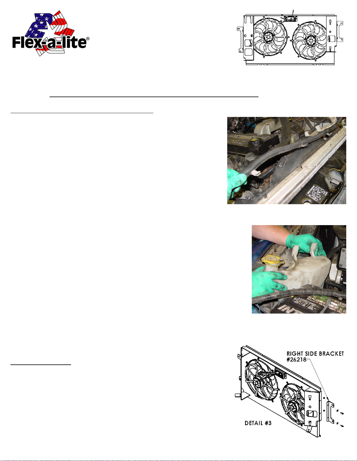
6. Remove upper hose from radiator and hold off to the side for clearance.
7. Disconnect the windshield wash reservoir from the shroud by pressing the 2
locking “buttons” on the backside of the the tank towards the shroud and
lifting up at the same time. It is not required to remove the tank entirely, just
hold tank off to the side. see detail 2.
8. Using 10mm socket, remove the 4 bolts (2 left side and 2 right side) that
hold the shroud in place. KEEP these bolts for installation of new fan.
9. Remove 2 small clips that hold the top of the factory shroud to the top of
the radiator.
10. Locate lower wire harness fastened to the lower part of the factory
shroud. Unfasten harness from the factory shroud. NOTE: Do not disconnect
harness from electrical system
11. Remove OEM clutch fan. This can be accomplished by turning the large
nut on the engine side of the fan clockwise. NOTE: Careful not to let the fan
hit the radiator core when it is spun loose from the engine.
12. Lift out the fan and shroud together to avoid any damage to the radiator
core.
INST ALLATION:
1. Start by attaching the side brackets to the shrouds with hex bolts and lock
nuts provided. see detail 3.
2. Place the coolant overflow bottle on the new shroud by aligning the tab on
the bottom of the bottle with the support tab on the bottom of the shroud. Push
bottle into shroud and slide down to lock in place.
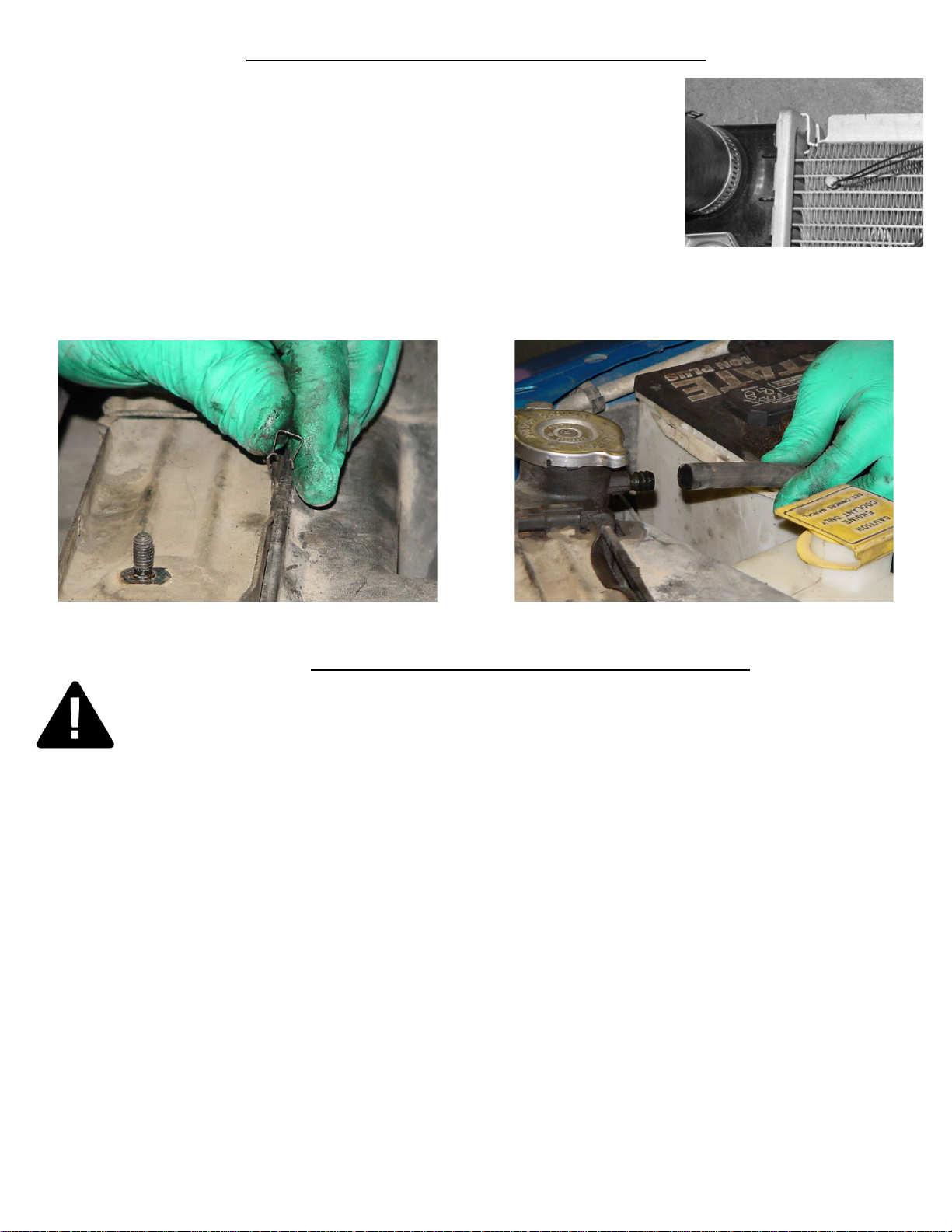
3. Locate the temperature sensor in the kit bag. Insert the temperature sensor
into the radiator fins near the radiator inlet. Leave 1/4” or less protruding
from the surface of the radiator for optimum performance. The wires will
run out through the top corner of the fan shroud. These will be used later
while wiring the VSC. see detail 4.
98262 page 1 of 4 rev . 03-24-08
DETAIL #1
DETAIL #2
Page 2
INSTALLATION (CONTINUED FROM PAGE 1)
4. Place the fan into the vehicle by placing the tabs on the bottom of the shroud into the
factory slots at the bottom of the radiator. NOTE: View old shroud t abs for reference .
5. Pull the new shroud to the radiator and place the 2 small clips from the factory
shroud to the top edge of the new shroud to hold in place. see detail 5.
6. Utilizing the 4 bolts from the factory shroud and the factory mounting holes, bolt the
new fan assembly in place.
7. Secure lower electrical harness so as not to be loose
8. Install the windshield wash reservoir to the new shroud in the same way as the
coolant overflow bottle. NOTE: See step #2 of this section for reference.
9. Replace coolant overflow bottle hose to radiator. see detail 6.
10. Attach the upper “inlet” hose to the radiator. Be sure the the drain plug is closed and refill the radiator with coolant.
11. Reinstall the battery cable from the primary battery to the secondary battery using a 10mm socket.
DETAIL #4
DETAIL #5 DETAIL #6
WIRING THE VARIABLE SPEED CONTROL
FOLLOW THESE INSTRUCTIONS CAREFULLY TO AVOID DAMAGING THE CONTROL
UNIT, FAN MOTORS, AND YOUR VEHICLE! WHEN CRIMPING WIRES, ALWAYS USE A
QUALITY CRIMPING TOOL (DO NOT USE PLIERS OR OTHER DEVICES).
1. Find the thick red and black wire bundles in the wiring kit. Use the yellow butt connectors to crimp the red wire to
the short red wire on the Variable Speed Control (VSC), and the black wire to the short black wire on the VSC (see
wiring diagrams below).
2. Determine the length needed to connect the red and black power leads to the battery terminals on the primary battery
on the drivers side and trim appropriately. Crimp a large yellow ring connector to the end of the black wire and connect
to the negative (-) battery terminal but DO NOT connect the red wire yet.
3. Find a convenient place to mount the circuit breaker between the VSC and the positive (+) battery terminal and use
the 2 screws provided to mount it securely. Cut the red wire at the point where you mounted the circuit breaker. Find the
red boot for the circuit breaker and lay it on the breaker as shown in detail #7. Crimp a small yellow ring connector to
the ends of the wires and connect them to the circuit breaker. NOTE: BE SURE TO CONNECT THE END COM-
ING FROM THE BATTERY POSITIVE (+) TERMINAL TO THE “BAT” TERMINAL ON THE CIRCUIT
BREAKER (COPPER COLORED). Once both positive (+) wires are connected to the circuit breaker, fold the top of
the boot over and press to fit. This will help insulate the circuit breaker from arcing. see detail #7.
4. Crimp a large ring connector to the positive (+) battery end of the power lead and connect it to the battery terminal.
5. Locate power distribution box (fuse box). Find a circuit that is “hot” when the key is in the “ON” position. NOTE:
DO NOT use the DRL or brake/ taillight fuse! Attach the included fuse tap to the fuse. Attach a pink female connec-
tor to the thin red wire included and attach to the fuse tap. Trim the wire so that it will reach the VSC. Attach pink
female connector to the other end of the wire and connect it to terminal #9 on the VSC.
98262 page 2 of 4 rev . 03-24-08
Page 3

DETAIL #7
6. Locate the wires going to the A/C clutch. Determine which wire is ground (-) and which wire is the positive (+)
trigger wire. Tap into the positive (+) trigger wire using the supplied thin green wire and the piggy-back connector
(blue). Determine the length needed to reach the VSC and trim to length. Attach a pink female connector and connect
this wire to terminal #8. NOTE: terminal #7 on VSC will be left open.
7. Find the 2 thin black wires coming from the temperature sensor that you installed
earlier in the radiator core. Determine the length of wire needed to reach the VSC.
IMPORTANT: strip the insulation of the wires back about 1” and fold the bare wire
back on itself to double the thickness of the wire before connecting the pink female
connectors (see detail #8). Then attach these wires to terminals #10 & 11. Both wires
need to be connected but it doesn’t matter which wire goes to each terminal.
DETAIL #8
8. If manual switche (Flex-a-lite #31148) has been purchased, attach it as follows: To override engine temperature to
turn fans off, connect the switch to terminal #5 on the VSC to send a negative (-) signal. To override engine temperature to turn fans on, connect the switch to terminal #6 on the VSC so that a negative (-) signal is sent.
black
blue
98262 page 3 of 4 rev . 03-24-08
Page 4

WIRING CONTINUED FROM PAGE 3
The Variable Speed Control has new features.
At the set temperature, the fans will come on at 60%; this reduces the load on your charging system. If the
temperature rises, the fan speed will increase. If your set temperature is 195°F, then between 195° and 205°
the fan speed will increase from 60% to 100%. So after a 10° rise from the set point, the fans will be running at
100%.
Initial Start-up and Adjustment Procedures
1. Turn ignition on. After 6 seconds, LED #L4 should light up. If not, check to make sure that there is 12 volts at terminal #9 on the VSC. The delay is to allow the starter to start the vehicle without the fans drawing any power.
2. With the engine running, engage the A/C. The fans should come on and cycle with the A/C clutch. LED’s #L1, L3
and L4 should be lit when the fans are running. If they do not turn on, verify that the A/C clutch is engaged and make
sure you have a positive signal when the clutch is engaged at terminal #8 on the VSC. Shut off A/C and let engine
continue to idle, or drive the vehicle a short distance to bring the engine to operating temperature (monitor the vehicle’s
temperature gauge).
3. Verify that operating temperature has been reached by feeling the upper radiator hose. Hot water should be flowing
through the hose into the radiator. If the fans have not cycled on yet, slowly adjust the screw on the VSC until the fans
cycle on. Turning the screw further in this direction will keep the engine at a lower temperature, and turning in the
opposite direction will keep the engine at a higher temperature. NOTE: THE TOTAL MOVEMENT OF THE AD-
JUSTMENT SCREW IS ABOUT 3/4 OF A TURN. TURNING THE SCREW BEYOND THE LIMITS WILL
DAMAGE THE UNIT! Once the desired temperature is set, let the engine continue to idle and make sure the fans will
cycle to maintain desired temperature. When the fans are running, LED’s #L1 and L4 should be lit.
The Flex-a-lite Limited Warranty
Flex-a-lite consolidated, 7213-45th St. Ct. E., Fife, WA 98242, Telephone No. 253-922-2700, warrants to the original purchasing user, that all Flex-a-lite products to be free of defects in material and
workmanship for a period of 365 days (1 year) from date of purchase. Flex-a-lite products failing within 365 days (1 year) from date of purchased may be returned to the factory throught the point of purchase,
transportation charges prepaid. If, on inspection, cause of failure is determined to be defective material or workmanship and not by misuse, accidental or improper installation, Flex-a-lite will replace the fan
free of charge, transportation prepaid. Flex-a-lite will not be liable for incidental, progressive or consequential damages. Some states do not allow the exlusion or limitation of incedental or consequential damages, so the above limitation or exclusion may not apply to you. This warranty gives you specific legal rights and you may have other rights, which vary from state to state. The Flex-a-lite warranty is in
compliance with the Magnuson-Moss Warranty Act of 1975.
98262 page 4 of 4 rev . 03-24-08
 Loading...