

Page 1
Dodge Ram ‘03-’08
Electric Fan Kit #183
Fits: 3.7 L. V6, 4.7 L. V8, & 5.7 L. V8 HEMI
INSTALLATION INSTRUCTIONS
REMOVAL OF EXISTING FAN AND SHROUD:
1. Make sure the engine is cool.
2. Disconnect negitive (-) battery cable from battery.
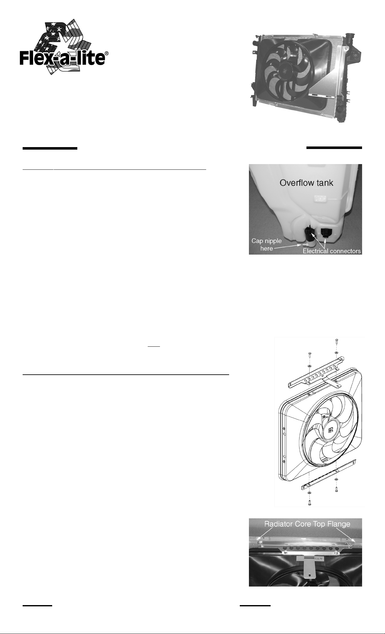
3. Disconnect electrical connector attached to windshield washer
motor on overflow tank.
4. Disconnect electrical connector directly attached to base of
overflow tank.
5. Disconnect windshield washer fluid tubing from motor on overflow
tank.
Note:
draining.
6. Disconnect coolant overflow hose from radiator filler neck.
7. Remove bolts 2ea. securing top of overflow tank to shroud.
8. Lift and separate radiator overflow tank from shroud and set aside.
This will be installed with the new fan kit later.
over and spill.
9. Remove bolts 2ea. holding the fan shroud to mounting bosses raised up from each of the two side tanks.
Save 1ea. bolt for installation of overflow support bracket #18303 later.
shroud just yet. The fan / clutch assembly is in the way.
(see Detail A)
Be prepared to cap nipple of motor to prevent fluid from
(see Detail A)
10. While holding clutch pulley, use a 36mm wrench & turn in direction of engine rotation (counter-clock-
wise) to loosen fan / clutch mounting-nut. Be careful not to drop fan / clutch assembly as it unscrews from
pulley.
Slowly
11.
Note:
Be careful not to scrape against the radiator core.
pull fan / clutch assembly
(see Detail A)
Note:
Be careful when setting aside tank as to not let it topple
and
shroud up and out simultaneously.
(Detail A)
Note:
Do not attempt to remove the
INSTALLATION OF NEW ELECTRIC FAN SHROUD:
12. An orange “Warning” sticker identifies top of shroud. Mount bracket
#18301 to top side of shroud and bracket #18302 to bottom side of shroud. Leave
brackets loose for adjustment later. Use the hex bolts and washers provided.
(see Detail B)
13. On the radiator core bottom flange, (viewed from under the vehicle) there
are two through bolts, securing accessories to the front of the radiator. Locate
and remove the nuts (engine side of radiator) exposing bolt threads.
14.
Lower Flex-a-lite electric fan / bracket assembly into engine compartment
and loosely mount top bracket #18301 to the radiator core’s top flange through
holes. Use 2ea. t-bolts, washers, & Nylock nuts provided.
15. Align bracket #18302 (from under side of radiator) to previously exposed
bolt threads and loosely fasten using previously removed nuts along with washers
provided.
driver’s side of radiator, this is intentional. The offset shroud placement allows for
better air flow when the overflow tank has been reinstalled.
seal is contacting the radiator core and compress the seal about 50%. It
may help to have a friend hold the fan against the core while tightening
brackets.
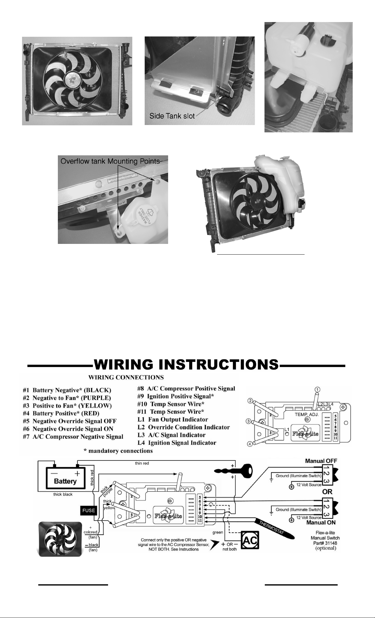
passenger side. Slot is at bottom of radiator molded onto side tank.
(see Detail E) Examine the old shroud’s bottom mounting tabs for
reference.
slot of bracket with side tank top mounting boss, and insert previously
removed factory bolt to secure top of bracket.
Note:
You will notice that the new shroud is positioned towards the
16. Before tightening the brackets, adjust the fan so that the rubber
17. Place the lower tab of bracket #18303 into the side tank slot on
While holding bottom of bracket #18303 in position, align top
(see step #9)
(see Detail C)
(see Detail D)
(Detail B)
INSTALLATION INSTRUCTIONS CONTINUED
(Detail C)
Rev. 04-06-10 Page 1 of 4 #99183
Page 2
(Detail D)
(Detail E)
(Detail F)
(Detail G)
18a. At this time you will want to reinstall the radiator overflow tank. Carefully lower the tank onto bracket
#18303; align the two plastic fingers protruding from bottom of tank with location slots on bottom shelf of
bracket.
bracket #18301. Secure overflow tank to bracket utilizing t-bolts, washers, & Nylock nuts provided.
(see Detail G)
(see Detail F)
18b. Attaching the top of the overflow tank involves alignment of the tanks original mounting points 2ea. to
19. Reconnect coolant overflow hose to radiator filler neck.
20. Reconnect windshield washer fluid tubing to motor on overflow tank.
21. Reconnect electrical connector directly attached to base of overflow tank.
22. Reconnect electrical connector attached to windshield washer motor on overflow tank.
#183 Assembly complete
WIRING INSTRUCTIONS CONTINUED
Rev. 04-06-10 Page 2 of 4 #99183
Page 3

1. Find the thick red and black wire in the kit. Deter mine the length needed to connect the red and black
power leads on the VSC to the battery terminals and trim appropriately. Crimp a large yellow ring connector to
the end of the black wire and connect to the negative (-) battery terminal. Connect the other end to the black
wire on the VSC with a large butt connector (yellow sleeve).
. Locate the fuse holder. DO NOT INSTALL THE FUSE UNTIL ALL THE WIRING IS COMPLETE. Attach
2
a large ring connector to one end and a yellow insulated butt connector to the other end of the fuse holder.
Attach the ring connector to the positive (+) terminal of the battery and connect the other end to the thick red
wire found in the kit. Deter mine the length of wire needed to reach from the fuse holder to the red wire on the
VSC and trim appropriately. Use a yellow insulated butt connector to connect this wire to the red wire on the
VSC.
3. Find a circuit that is “hot”, preferably in a fuse box, when the key is in the “on” position. Attach the included fuse tap to fuse. Attach a pink female connector to one end of the thin red wire (included) and connect
to fuse tap. Determine length of wire needed to reach the VSC and trim to appropriate length. Attach a pink
female connector to the end of the wire and connect to terminal #9 on VSC.
4. Locate wires going to A/C clutch. Determine which wire is ground and which is positive. Then attach
supplied thin green wire by way of a piggyback connector to the positive wire that activates the clutch. Attach
wire to terminal #8 on the VSC. Terminal #7 will be left open for this application.
5. Locate the temperature probe. Gently push the probe through fins in radiator as
close to the upper radiator hose as possible with ¼”-½” of the probe protruding out of
the front of the core. The rubber insulating cap should be used whenever possible to
insulate any of the probe coming through the front side of the radiator. Determine
length of wire needed to reach VSC. IMPORTANT: Strip the insulation on the tempera-
ture probe wires back about 1” and fold the wire on itself to effectively double the thickness of the wire before
connecting spade connectors. Then attach these wires to terminals #10 & #11. Both wires need to be connected, but it doesn’t matter which wire goes to each terminal.
6. If manual switches (Flex-a-lite #31148) have been purchased, attach them as following. To override
engine temperature to turn fans off, connect the switch to terminal #5 on VSC to send a ground signal. To
override engine temperature to turn fans on, connect the switch to terminal #6 on the VSC so that a ground
signal is sent.
7. Reconnect negative (-) battery cable to battery.
8. At this time install the provided fuse into fuse holder.
Initial Set-up and Adjustment
1. Turn ignition on. After 5-6 seconds, LED #4 should light up. If not, check to make sure that you have 12
Volts at terminal #9 on VSC. The delay is to allow starter to start the vehicle without the fans drawing any
power.
2. With your engine running, engage the A/C. Your fan should come on and cycle with the A/C clutch. LED’s
#1, 3, and 4 should be lit when fans are running. If they do not turn on, verify that the A/C clutch is engaged
and make sure that you have the appropriate wires connected to the correct terminals on the VSC. Shut off A/C
and let engine continue to idle until it has reach normal operating temperature.
3. Verify that normal operating temperature has been reached by feeling upper radiator hose. Hot water
should be flowing through the hose into the radiator. Adjust the screw on the VSC counterclockwise for a cooler
setting or clockwise for a warmer setting. Once desired temperature is set, let engine continue to idle to make
sure the fan will cycle to maintain desired temperature. When fan is running, LED’s #1 and 4 should be lit.
Rev. 04-06-10 Page 3 of 4 #99183
Page 4

Rev. 04-06-10 Page 4 of 4 #99183
 Loading...