

Flex-a-Lite 130-Pusher, 230-Pusher, 140-Pusher, 240-Pusher Installation Instructions Manual
Page 1
130&140 230&240
Pusher Fans
Installation Instructions
Model 130 - Single fan w/ thermo-
Pusher
Model 140 - Single fan w/o ther-
Pusher
static control &
A/C relay
mostatic control &
A/C relay
Model 230 - Dual fan w/ thermo-
Pusher
Model 240 - Dual fan w/o ther-
Pusher
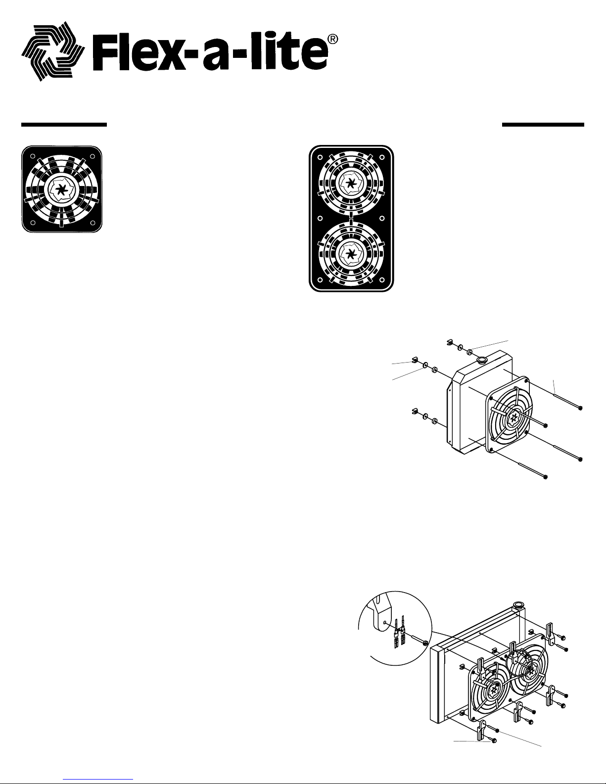
Through Core Mounting Instructions
(SEE DIAGRAM “A”)
1.Position the electric fan against the front of the
radiator , and mark location of the holes on radiator .(Some
applications may have A/C condensers and/or tranny
coolers on the front of the radiator. Additional adjustments or modifications may be necessary for installation)
2. Holding fan in position, rotate fan blades to make sure
they are free of obstructions.
3. With a small Phillips screwdriver pass through the
marked holes, carefully spread the fins to allow easy passage for the nylon bolts (4 for the single fan unit, 6 for the
double fan unit). Pass the bolts through the shroud holes
then twist the bolts through the radiator . Note: Be sure to
pass through the motor lead connectors when inserting the
bolt through the top middle hole of the double unit. See
expanded view on diagram B.
4. Slide the rubber washer , then the steel washer onto the nylon bolt and
finger tighten wing nuts until snug.
5. Once again, rotate fan blades to insure that they are free of obstruction.
Wing Nut
Steel Washer
static control & A/C
relay
mostatic control &
A/C relay
Diagram A
Rubber Disk Spacer
Nylon Bolt
OR
Radiator Support Channel Or Frame Installation
(SEE DIAGRAM “B”)
1. Attach frame mounting brackets to fan using
nylon bolts, cut them to 1", using wing nuts to
secure. Note: Be sure to pass through the motor lead
connectors when inserting the bolt through the top
middle hole of the double unit. See expanded view
on diagram B.
2. Position fan to desired location, mark holes on
radiator channels or frame.
3. Rotate fan blades to insure that they are free of
obstruction.
4. On the marked hole locations drill 13/64" holes.
5. Secure the fan to radiator using the provided
1/4" x 1" self tapping screws.
6. Once again, rotate fan blades to insure that they
are free of obstruction.
(See circled areas for location of
installed clamp. Wire holders
shown in inset.)
Page 1 of 6
Black Nylon
Clamps
Motor Leads
Radiator
Channel Frame
Self T apping
Screw
Diagram B
Frame
Mounting
Brackets
Nylon Bolt
(cut to 1")
Page 2
Wiring Instructions
Note: Each connection shown in this section is mandatory for operation.
1. Disconnect battery .
2. Attach black motor wire(s) to M+.
3. Attach white motor wire(s) to M-.
4. Connect the “+” terminal to a 12 volt positive (+)
power source, e.g. fuse box. Use the wire provided in
the kit.Note: To stop the fan unit from operating when
the vehicle is shut off, attach this wire to an ignition
switched 12 volt power source.
5. Connect the “B” terminal to a 12 volt positive (+)
power source, e.g. Positive side of battery , or alternator . Use the wire and inline fuse provided in the
kit.
6. If you have air conditioning: Connect the “C”
terminal to the positive(+) side of the air conditioning
compressor . Splice into the A/C clutch positive wire
using the 3-way connector and wire provided in the
kit. Air Conditioning Relay (Activates fan(s) when A/C
is turned on)
7. Connect the “G” terminal to ground, i.e. chassis,
negative (-) side of the battery . Use the wire
provided in the kit.
Control Box Terminals
Mandatory Connections
M+ Black motor wire(s)
M- White motor wire(s)
+ 12 volt positive source
G Ground
B 12 volt positive source
C Air conditioning relay
Control Box
C
M
3-way
connector
A/C positive (+)
wire from clutch
12 Volt Positive Source
B
Fuse
12 Volt Source
Optional Connection
M Manual switch
Ground
G
Black Motor(s)
wire(s)
M+
+
White motor(s)
wire(s)
M-
12 Volt Source
1 2 3
Ground
(Illuminate switch connection
for Flex-a-lite Part #31 148)
Wiring Instructions For Accessories
Note: Connection shown in this section is optional and is not crucial for standard operation
Manual Switch (Allows manual activation of the fan(s)
1. Connect the “M” terminal to terminal 1 of the switch. Attach separate wire to terminal 2, attach other
end of the same wire to a 12 volt positive source. T o illuminate switch, connect a ground to
terminal 3.
Note: (Instructions based on Flex-a-lite manual switch, part number 31148. Manual switch not included)
*WARNING: If not using Flex-a-lite’ s illuminated switch
(PN #31148) you must disconnect the switch ground.
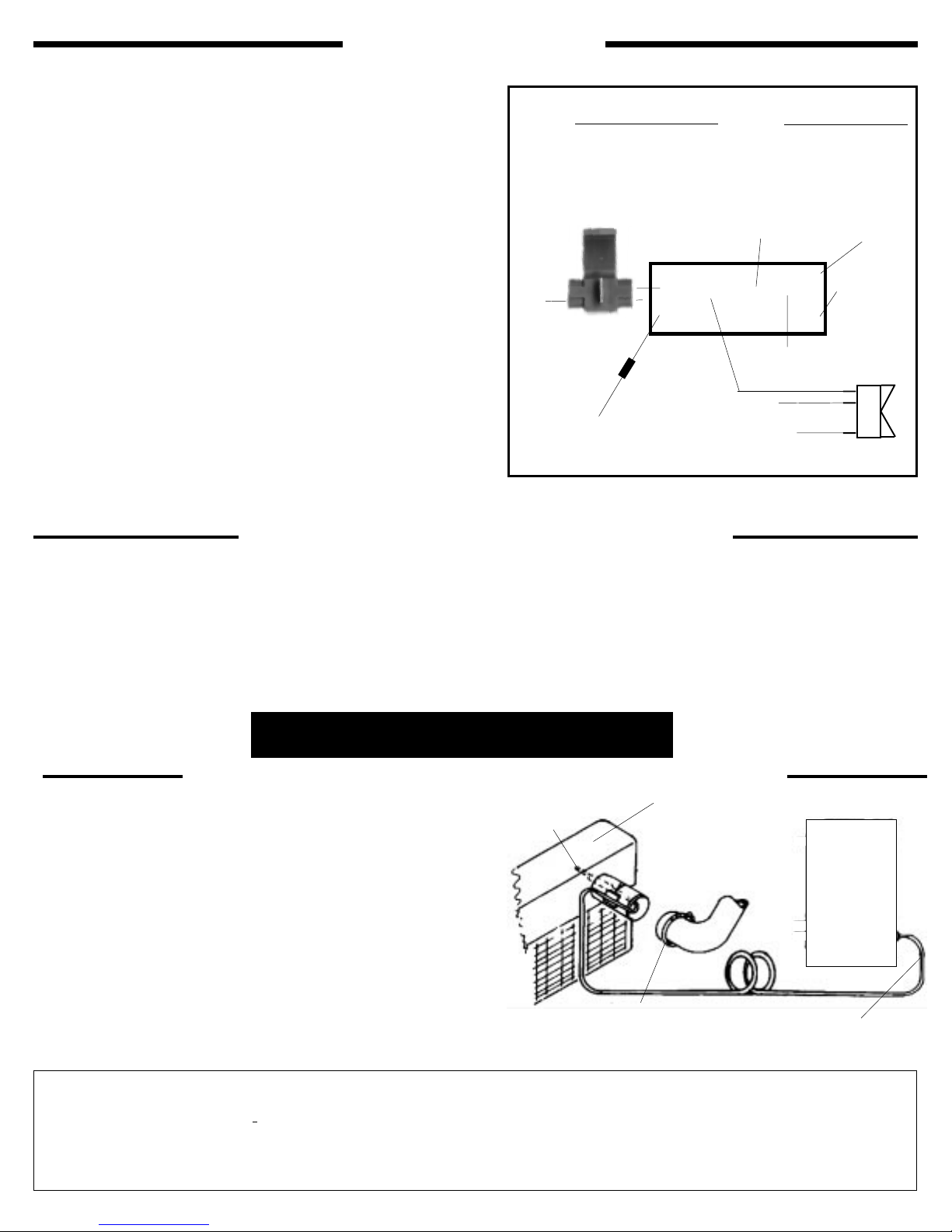
T emperature Control Sensor Bulb Installation
1. Loosen upper radiator hose at the radiator , pull the
hose off the radiator inlet pipe.
T emp.
Sensing Bulb
2. Insert sensor bulb, bend the sensor bulb tube
around the end of the radiator inlet pipe.
(The tube is hollow , do not kink. Use wide bends.)
3. Place the sensor gasket (rubber piece with the slit)
between the sensor bulb tube and radiator inlet
pipe. Be sure the tube lays in the slit of the rubber
gasket.
4. W rap vinyl tape around the inlet pipe and sensor
tube at least twice.
5. Replace radiator hose, tighten clamp. (Do not overtighten) Note: You must use a screw-type hose
clamp, some original equipment clamps will leak.
The Flex-a-lite Limited Warranty
Flex-a-lite Corporation, 7213-45th Street Court East, Fife, Washington 98424, Telephone No. 253/922-2700, warrants to the original purchaser
user, all Flex-a-lite products to be free of defects in material and workmanship for a period of 365 days (1 year) from date of purchase. Flex-alite products failing within 365 days (1 year) from date of purchase, may be returned to the factory through the point of purchase, transportation charges prepaid. If, on inspection, cause of failure is determined to be defective material or workmanship and not by misuse, accident, or
improper installation, Flex-a-lite will replace the fan free of charge, transportation prepaid. Flex-a-lite will not be liable for incidental,
progressive, or consequential damages. Some states do not allow the exclusion or limitation of incidental or consequential damages, so the
above limitation or exclusion may not apply to you. This warranty gives you specific legal rights and you may also have other rights, which vary
from state to state.
Page 2 of 6
Radiator Top T ank
Bend capillary tube as shown.
Lay cap tube into sensor
gasket groove & wrap with
vinyl tape.
Hose clamp over sensor gasketDo Not Position Clamp Screw
Over Gasket.
Control
Capillary Tube
Do not bend less than
1/4" radius.
Box
Page 3

Instructions ’installation
Modèle propulsif 130-Ventilateur
unique avec contrôle à thermostat
et relais de climatisation
Modèle propulsif 140-Ventilateur
unique avec contrôle à thermostat
et relais de climatisation
Modèle propulsif 230-Double
ventilateur avec contrôle à
thermostat et relais de
climatisation
Modèle propulsif 240-Double
ventilateur avec contrôle à
thermostat et relais de
climatisation
Instructions d’installation à travers le corps
(VOIR LE DIAGRAMME «A»)
1. Placez le ventilateur électrique contre l’avant du
radiateur et marquez les trous de montage. (Dans
certaines applications, il peut y avoir des condensateurs de
climatisation et/ou des refroidisseurs devant le radiateur .
Ecrou à oreilles
Rondelle en acier
Diagramme A
Entretoise en caoutchouc
en forme de disque
Boulon en
nylon
Des réglages ou des modifications supplémentaires
pourront être nécessaires afin de procéder à l’installation).
2. Tournez les pales du ventilateur pour vous assurer de
l’absence d’obstructions.
3. A l’aide d’un petit tournevis à tête étoilée, passez à travers les
trous marqués et écartez avec soin les ailettes pour faciliter le passage des boulons en nylon (4 pour l’unité à ventilateur unique, 6 pour l’unité
à double ventilateur). Faites passer les boulons dans les trous du capot de
refoulement, puis tordez-les à l’intérieur du radiateur . Remarque : Veillez à passer à
travers les connecteurs des fils du moteur quand vous insérez les boulons dans le trou supérieur
central de l’unité à double ventilateur . Voir la vue éclatée, au diagramme B.
4. Faites glisser la rondelle en caoutchouc, puis la rondelle en acier , sur le boulon en nylon, puis serrez
les écrous à oreille à la main jusqu’à ce qu’ils soient bien assujettis.
5. Une fois de plus, tournez les pales du ventilateur pour vous assurer de l’absence d’obstructions.
OU
Installation par les rainures de support ou le châssis du radiateur
(VOIR LE SCHEMA «B»)
1. A l’aide des boulons en nylon, fixez les supports de montage du châssis au ventilateur , puis coupez-les à 254 mm
(1 po), et assujettissez-les à l’aide des écrous à oreilles.
2. Placez le ventilateur à l’endroit désiré, et marquez les
trous dans les rainures ou le châssis du radiateur .
3. Tournez les pales du ventilateur pour vous assurer de
l’absence d’obstructions.
4. Forez des trous de 5,15 mm (13/64 po) à l’emplacement des
marques.
5. Fixez le ventilateur au radiateur à l’aide des vis
autotaraudeuses de 6,53 mm x 254 mm (1/4 po x 1 po).
6. Vérifiez la rotation du ventilateur .
Page 3 of 6
Pinces noires
en nylon
Fils du moteur
(Voir les zones
encerclées pour
l’emplacement de la
pince installée. Les
porte-fils sont illustrés
dans l’encadré)
Vis autotaraudeuse
Châssis à rainures
du radiateur
Diagramme B
Supports de
montage du
châssis
Boulon en nylon
(coupé à 2,54 cm (1 po))
Page 4

Instructions de câblage
Remarque : Chaque connexion illustrée dans cette section est exigée pour permettre le fonctionnement.
1. Débranchez la batterie.
2. Reliez le ou les fils noirs du moteur à M+
3. Reliez le ou les fils blancs du moteur à M-.
4. Connectez la borne positive “+” à une boîte à fusibles de
source d’alimentation positive (+) de 12 volts basse
intensité. Utilisez pour ce faire le fil contenu dans le
kit.
Remarque : Connectez à la source d’allumage si vous
ne voulez pas que l’unité continue de fonctionner une
fois que le moteur a été coupé.
5. Connectez la borne “B” à une source d’alimentation
positive (+) de 12 volts haute intensité, par exemple au
côté positif de la batterie ou de l’alternateur. Utilisez
pour ce faire le fil et le fusible en ligne contenus dans le
kit.
6. Connectez la borne “C” au côté positif (+) du
compresseur de climatisation. Raccordez au fil positif
de l’embrayage de climatisation à l’aide du
connecteur à trois broches et du fil contenus dans le
kit. Relais de climatisation (actionne le ou les
ventilateurs lorsque la climatisation est mise en
marche).
7. Connectez la borne “G” au côté terre, c’est à dire au
châssis, côté négatif (-) de la batterie. Utilisez pour ce
faire le fil contenu dans le kit.
Fil positif de la climatisation
s
Source de courant de haute
intensité de 12 volts positifs
Bornes et connexions du coffret de commande
Connexions obligatoires
M+ Fils noirs du moteur
M- Fils blancs du moteur
+ Source de 12 volts basse intensité
G Terre
B Source de courant de haute
intensité de 12 volts
s
C Relais de la climatisation
Connecteur
à 3 voies
Coffret de commande
C
M
B
Disjoncteur
BAT
AUX
Source de
12 volts
Terre
(illumination du commutateur)
Connexions facultatives
M Commutateur manuel
T erre
G
+
Source de courant
de faible intensité
de 12 volts
Instructions de câblage des accessoires
Remarque : La connexion illustrée dans cette section, facultative, n’est pas cruciale au fonctionnement standard.
Commutateur manuel (pour le fonctionnement manuel du ou des ventilateurs)
1. Connectez la borne «M» à la borne 1 du commutateur. Fixez le fil séparé à la borne 2, puis fixez l’autre
extrémité de ce fil à une source d’alimentation positive de 12 volts. Pour illuminer le commutateur,
connectez une terre à la borne 3.
Remarque : (Ces instructions supposent l’emploi d’un commutateur manuel Flex-a-lite, n° de pièce 31148.
Commutateur manuel non inclus)
Installation de la poire de détection pour le contrôle de température
1. Desserrez le tuyau supérieur du radiateur, puis
retirez-le de la conduite d’admission du radiateur.
Poire de détection
de température
2. Insérez la poire de détection, puis courbez le tube de
la poire de détection autour de l’extrémité de la
conduite d’admission du radiateur. (Le tube est creux,
ne le tordez pas. Courbez-le légèrement).
3. Placez le joint du détecteur (pièce en caoutchouc
comportant une fente) entre le tube de la poire de
détection et la conduite d’admission du radiateur.
Veillez à ce que le tube soit calé dans la fente du joint
en caoutchouc.
4. Faites passer la bande en vinyle au moins deux fois
autour de la conduite d’admission et du tube du
Collier de serrage du tuyau par dessus
le joint du détecteur. Ne placez pas la
vis de serrage sur le joint.
détecteur.
5. Remettez le tuyau du radiateur en place, puis serrez
la pince. (Ne serrez pas à l’excès).
Garantie limitée de Flex-a-lite
Flex-a-lite Corporation, 7213-45th Street Court East, Fife, Washington 98424, numéro de téléphone 253/922-2700, garantit à l’ac heteur d’origine que tous les produits Flex-a-lite sont
exempts de défauts de matériaux et de fabrication. Cette garantie est valable pendant 365 jours (1 an) suivant la date d’achat. Si, dans les 365 jours (1 an) suivant la date d’achat, des
produits Flex-a-lite se révèlent défectueux, vous pouvez les réexpédier à l’usine, frais d’expédition prépayés. Si l’inspection détermine que la cause de la panne est due à un défaut de
matériau ou de fabrication, et non à un usage abusif, à un accident ou à une installation incorrecte, Flex-a-lite remplacera gratuitement le produit, frais d’expédition prépayés. Flex-a-lite
décline toute responsabilité en cas de dommages fortuits, progressifs ou connexes. Certains états n’autorisant pas l’exclusion ou la limite des dommages fortuits, il est possible
que la limite ou l’exclusion ci-dessus ne s’applique pas à votre cas. Cette garantie vous donne des droits légaux spécifiques, et vous pouvez également avoir d’autres droits,
varient d’un état à un autre.
Page 4 of 6
Réservoir supérieur
du radiateur
Courbez le tube capillaire
comme illustré. Placez-le
dans la rainure du joint du
détecteur et enveloppez-le
d’une bande en vinyle.
Boîtier de
contrôle
Tube capillaire. Ne le
courbez pas à moins
d’un rayon de 254
mm (1/4 po).
qui
Page 5

Instrucciones de instalación
Modelo 130 de empuje -
Ventilador simple con control
termostático y relé de aire
acondicionado.
Modelo 140 de empuje-
Ventilador simple sin control
termostático y relé de aire
acondicionado.
Instrucciones de montaje a través del núcleo
(VEA EL DIAGRAMA «A»)
1. Coloque el ventilador eléctrico contra el frente del
radiador y marque los orificios de montaje (Algunas
aplicaciones pueden tener condensadores de aire
acondicionado y o enfriadores en la parte frontal del
radiador. Pueden necesitarse modificaciones o ajustes
adicionales para la instalación).
2. Haga girar las aspas del ventilador para asegurarse de
que no tengan obstrucciones.
3. Con un pequeño destornillador Phillips, pase por los
orificios marcados, separe con cuidado las aletas para
permitir que pasen libremente los tornillos de nilón (4
para la unidad de ventilador simple y 6 para la de
doble). Haga pasar los tornillos por los orificios de la
gualdera y, luego, tuérzalos para que atraviesen el
radiador. Nota: Asegúrese de pasar por los conectores de
conductores del motor al insertar el tornillo a través del
orificio mediano superior de la unidad doble. V ea la
vista ampliada en el diagrama B.
4. Deslice la arandela de caucho y, luego, la de acero sobre
el tornillo de nilón y apriete con los dedos las tuercas de
mariposa hasta que queden sin holgura.
5. Una vez más, haga girar las aspas del ventilador para
asegurarse de que no tengan obstrucciones.
Tuerca de mariposa
Arandela de acero
Modelo 230 de empuje -
Ventilador doble con control
termostático y relé de aire
acondicionado.
Modelo 240 de empuje -
Ventilador doble sin control
termostático y relé de aire
acondicionado.
Diagrama A
Espaciador de disco de caucho
Tornillo de nilón
O BIEN,
Canal de soporte del radiador o instalación de armazón
(VEA EL DIAGRAMA “B”)
1. Sujete las ménsulas de montaje del armazón al
ventilador , utilizando tornillos de nilón y, luego,
córtelas a 2.54 cm (1 pulgada), utilizando tuercas de
mariposa para sujetarlas.
2. Coloque el ventilador en la ubicación deseada y marque
los orificios en los canales del radiador o el armazón.
3. Haga girar las aspas del ventilador para asegurarse de
que no tengan obstrucciones.
4. En los sitios marcados para los orificios, haga
perforaciones de 5.15 mm (13/64").
5. Fije el ventilador al radiador , utilizando los tornillos
autorroscantes de 6.35 mm x 25.4 mm (1/4" x 1").
6. Verifique la rotación del ventilador
(Vea las zonas encerradas
en círculos para encontrar
la abrazadera instalada. Los
portaalambres se muestran
en la inserción).
Page 5 of 6
Conductores del
Abrazaderas
negras de nilón
motor
Tornillo autorroscante
Diagrama B
Armazón de canales
del radiador
Ménsulas de
montaje del
armazón
Tornillo de nilón
(cortado a 2.54 cm (1"))
Page 6

Instrucciones de cableado
Nota: Todas y cada una de las conexiones que se muestran en esta sección son obligatorias para el
funcionamiento.
1. Desconecte la batería
2. Acople el o los conductores negros del motor a M+.
3. Acople el o los conductores blancos del motor a M-.
4. Conecte la terminal positiva “+” a una caja de fusibles
de fuente de alimentación positiva (+) de 12 voltios.
Use el conductor que se proporciona en el estuche.
Nota: Conecte a la fuente de encendido si no desea que
la unidad funcione después de que se detenga el motor.
5. Conecte la terminal “B” a una fuente de alimentación
positiva (+) de 12 voltios, o sea, al lado positivo de la
batería o el alternador. Utilice el cable y el fusible en
línea que se proporcionan en el estuche.
6. Conecte la terminal “C” al lado positivo (+) del
compresor de aire acondicionado. Haga un empalme
en el conductor positivo del embrague de aire
acondicionado, utilizando el conector en tres sentidos
y el conductor proporcionado en el estuche. Relé de
aire acondicionado (activa el o los ventiladores
cuando se enciende la corriente de aire
acondicionado).
7. Conecte la terminal “G” a tierra, o sea, al chasís o el
lado negativo (-) de la batería. Utilice el conductor
proporcionado en el estuche.
del aire acondicionado
Conductor positivo
s
Positivo de bajo
amperaje de 12 volts
Terminales y conexiones de la caja de control
Conexiones obligatorias
M+ Conductor(es) negro(s) del motor
M- Conductor(es) blanco(s) del motor
+ Fuente de bajo amperaje de 12 voltios
G Tierra
B Fuente de alto amperaje
de 12 voltios
s
C Relé de aire acondicionado
Conector en
tres sentidos
Caja de control
C
M
B
Disyuntor
BAT
AUX
Fuente de
alimentación de 12
voltios
Conexiones opcionales
M Interruptor manual
Tierra
G
+
Fuente de bajo
amperaje de 12 voltios
Tierra
(se ilumina el interruptor)
Instrucciones de cableado para accesorios
Nota: Las conexiones que se muestran en esta sección son opcionales y no son cruciales para el
funcionamiento estándar
Interruptor manual (Permite la activación manual del o los ventiladores)
1. Conecte la terminal «M» a la 1 del interruptor. Acople el conductor separado a la terminal 2 y acople el
otro extremo del mismo alambre a una fuente positiva de 12 voltios. Para iluminar el interruptor,
conecte una tierra a la terminal 3.
Nota: (Las instrucciones se basan en un interruptor manual Flex-a-lite, pieza número 31148. No se incluye el
interruptor manual).
Instalación del bulbo sensor de control de temperatura
1. Afloje la manguera superior del radiador y sáquela del
tubo de entrada.
2. Inserte el bulbo sensor, doblando su tubo en torno al
extremo del tubo de entrada del radiador.
(El tubo es hueco, no produzca sesgos. Use vueltas
amplias).
3. Coloque el empaque sensor (la pieza de caucho con la
hendidura) entre el tubo del bulbo sensor y el de
entrada del radiador. Asegúrese de que el tubo repose
en la hendidura del empaque de caucho.
4. Aplique al menos dos vueltas de cinta de vinilo en
torno al tubo de entrada y el del sensor.
5. Vuelva a colocar la manguera del radiador y apriete la
abrazadera (no apriete en exceso).
Garantía limitada de Flex-a-Lite
Flex-a-lite Corporation, 7213-45th Street Court East, Fife, Washington 98424, teléfono número 253-922-2700, le garantiza al usuario comprador original, que todos los productos de Flex-a-lite
estarán libres de toda clase de defectos de materiales y mano de obra durante un periodo de 365 días (1 año) a partir de la fecha de compra. Los productos de Flex-a-lite que fallen dentro de los
365 días siguientes (1 año) a la fecha de compra, podrán regresarse a la fábrica, con los cargos de transporte pagados por adelantado. Si al efectuar una inspección se determina que la causa del
fallo es un defecto de los materiales o la mano de obra y no el mal uso, un accidente o una instalación inadecuada, Flex-a-lite reemplazará el ventilador sin cargo alguno, con el transporte pagado
por adelantado. Flex-a-lite no será responsable de daños incidentales, progresivos ni consecuentes. Algunos estados no permiten la exclusión ni la limitación de daños incidentales o
consecuentes, de modo que es posible que la limitación o exclusión precedente no se le aplique. Esta garantía le concede derechos legales específicos y es posible que tenga también otros,
que varían de un estado a otro.
Bulbo sensor de
temperatura
Abrazadera de manguera sobre el
empaque sensor. No ponga el tornillo de
la abrazadera sobre el empaque.
Page 6 of 6
Depósito superior
del radiador
Doble el tubo capilar como
se indica. Coloque el tubo de
casquete en la ranura del
empaque sensor y
envuélvalo con cinta de
vinilo.
Caja de
control
Tubo capilar . No lo
doble en un radio de
menos de 6 mm (1/4").
99875 7/00
 Loading...