

Page 1
Electra-Fan 10 & 20
Installation Instructions
HEX WRENCH
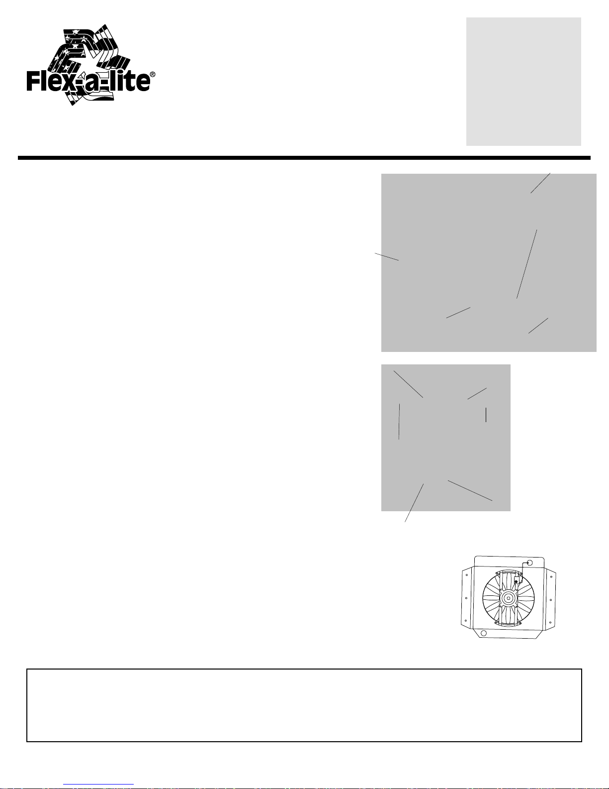
Assembly:
1. Fasten motor to bracket.
2. Attach the ring fan to the motor shaft: (See Diagram A)
T o PUSH air through the radiator , place fan in front of radiator:
Attach fan so “Electra Fan”, printed on the fan hub, faces the electric
motor. Center fan hub in bracket, then tighten set screw on the flat
side of the motor shaft.
T o PULL air through the radiator, place fan behind radiator:
Attach fan so “Electra Fan”, printed on the fan hub, faces away from
the electric motor. Center fan in bracket, then tighten set screw on
the flat side of the motor shaft.
MOTOR
IMPORT ANT: FAN MUST ROTATE FREELY
Attaching electric fan to radiator:
(See Diagrams B & C)
1. Position the electric fan so that the temperature sensor bulb can reach
the top of the radiator inlet hose connection.
cover the finned area. (DIAGRAM C)
2. Once position is determined, carefully pass a small Phillips screwdriver
through the bracket and radiator fins.
Caution: Be careful not to damage the tubes or core of the radiator.
3. Pass the metal bolts through the two curved bracket pads, then
through the radiator (opposite side of where screwdriver went through
the radiator), and then through the electric fan bracket. Fasten the (4)
washer and nuts provided to the metal bolts.
Caution: Do not over tighten. (DIAGRAM B)
IMPORT ANT: FAN MUST ROTATE FREELY
Note: Electric fan should
DIAGRAM A
BRACKET
CURVED
BRACKET
PLASTIC
BOLT
CURVED
BRACKET
SET
SCREW
FAN BLADE
DIAGRAM B
WASHER
NUT
ELECTRIC
FAN
BRACKET
DIAGRAM C
The Flex-a-lite Limited Warranty
Flex-a-lite Consolidated, 7213-45th St. Ct. E. Fife, W A 98424, Telephone No. 253-922-2700, warrants to the original purchasing user, that all Flex-a-lite products to be free of defects in material and
workmanship for a period of 365 days (1 year) from date of purchase. Flex-a-lite products failing within 365 days (1 year) from date of purchase may be returned to the factory through the point of
purchase, transportation charges prepaid. If, on inspection, cause of failure is determined to be defective material or workmanship and not by misuse, accidental or improper installation, Flex-a-lite will
replace the fan free of charge, transportation prepaid. Flex-a-lite will not be liable for incidental, progressive or consequential damages. Some states do not allow the exclusion or limitaion of
incidental or consequential damages, so the above limitation or exclusion may not apply to you. This warranty gives you specific legal rights and you may have other right s, which vary from state to state.
The Flex-a-lite warranty is in compliance with the Magnuson-Moss Warranty Act of 1975.
rev. 07-08-05 99963
Page 2
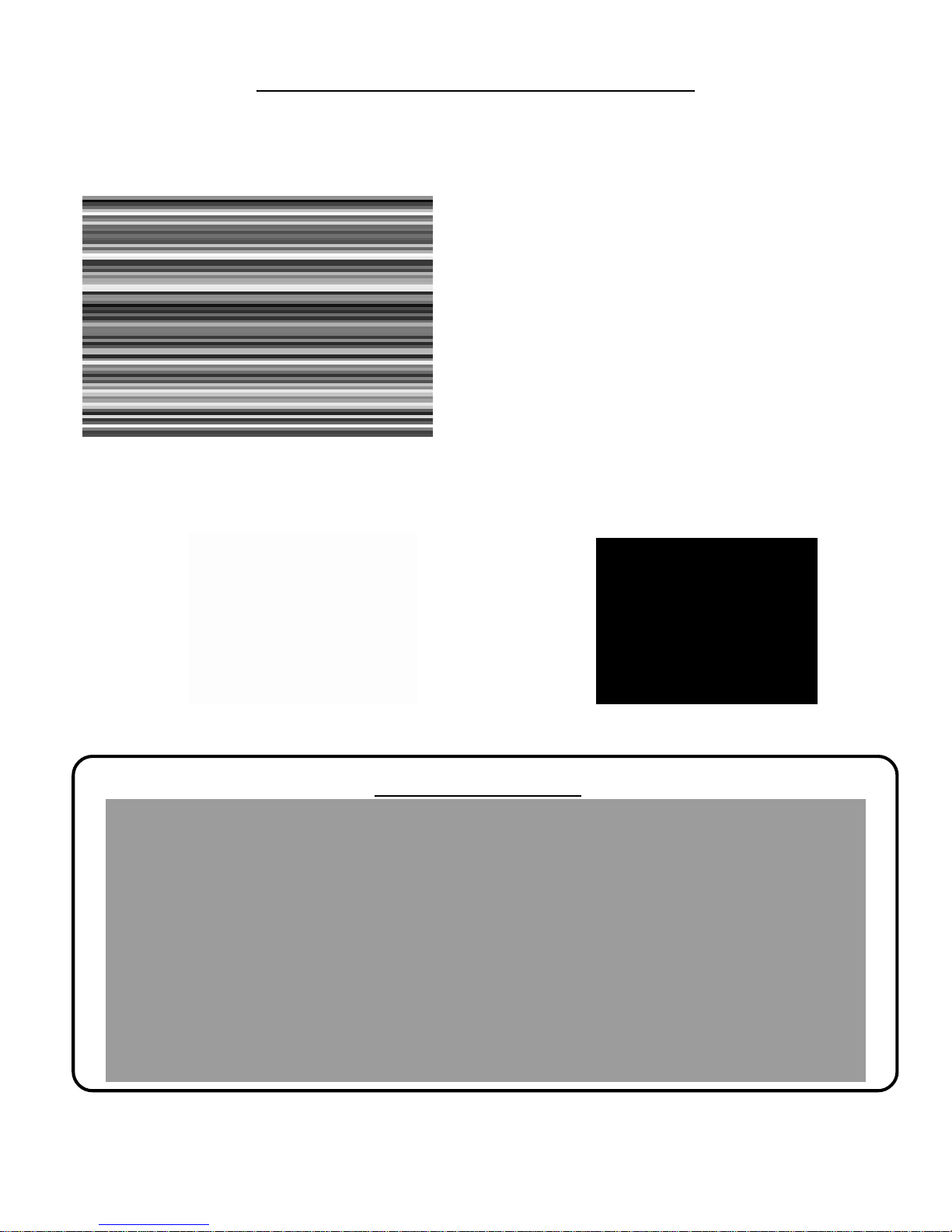
Assembly & Installation Instructions
1. Att ach the temp. control unit to the mounting bracket using
the hardware provided, then push the knob onto the control
shaft.
2. The control can be mounted to any flat surface in the
engine compartment that is within 18” of the radiator inlet
hose. Use the 3 mounting screws provided.
3. Insert the temp. sensor as close to the inlet hose as
possible, then push the rubber insulator cap over the end of
the sensor as shown.
4. Connect the “C” terminal on the control unit to the positive
(+) lead on electric fan unit. For automatic operation,
connect the “2” terminal on the control unit to a fused positive
(+) source that is capable of powering the electric fan unit
(refer to wiring diagram below). Use the female connectors
provided.
5. If manual control is desired, use Flex-a-lite P/N 31 148.
Refer to wiring diagram below.
a-lite manual switch, DO NOT connect the ground (-)
wire to the switch!
NOTE: If not using a Flex-
Insert the temp. sensor near the inlet hose... Then push the insulator cap over the end of the
sensor.
Wiring Diagram
rev. 07-08-05 99963
 Loading...