

Page 1
R2
Radio Transmitter
for Fujifilm
FPRRR2TF
Page 2

Flashpoint R2 Radio Transmitter for Fujilm
Thank you for choosing Flashpoint!
The Flashpoint R2 Radio System transmits TTL data directly to the vast R2 Family
of Flash which is fully compatible with many camera TTL systems, as well as select
manually controlled strobes and monolights. Featuring multi-group triggering,
stable signal transmission, and real-time sync, it gives photographers unparalleled
exibility and control over their strobist setups. The transmitter features highspeed sync and a pass-through for a speedlite, as well. This TTL wireless ash
trigger only applies to FUJIFILM cameras.
The incredible range of these compact and lightweight units as well as their
integrated functions and features make them the rst choice of professional
photographers. If you have any questions or concerns, please feel free to
contact us at Brands@Adorama.com
Features
• Remote TTL and Manual power control
• Multi Group triggering and channel security
• Clear LCD readout panel
• Industry benchmark sync range and interference avoidance
• Built in laser AF assist lamp with laser crisscross pattern for instant autofocus
even in complete dark on low contrast surfaces (on compatible cameras)
• HSS for shutter speeds up to 1/8000 second with compatible
cameras and strobes
• 1 year warranty
2
Page 3

For Your Safety
• Always keep this product dry.
• Do not use in rain or in damp conditions.
• Stop using this product if it breaks open due to internal shifting,
falling or strong impact.
• STRONG electric shock may occur if you touch the components inside it.
• Do not re ash directly into the eyes, especially those of babies and pets,
within short distances. Visual impairment may occur.
• Do not use ash units in the presence of ammable gases, chemicals
and other similar materials.
• Do not leave or store the unit if the ambient temperature is over 122°F /50°C
(e.g. in automobile in the sun). The electronic parts may be damaged.
• Do not insert metal parts into any equipment.
• Do not touch the electrical contacts on the ash or battery or contact them with
any conductive materials.
• Do not use the unit to support other equipment. For example, do not lift your
camera by the radio.
• The radio has a locking pin to ensure secure operation. To avoid damage,
completely unscrew the locking ring before removing the ash.
• Store the radio with the batteries removed. Keeping them inside can lead to
battery cell leakage, voiding the warranty.
3
Page 4
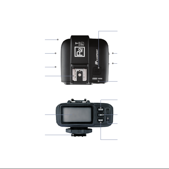
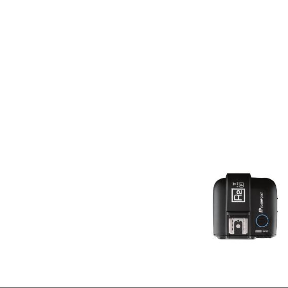
Name of Parts
Body / Transmitter
Battery
Compartment
Micro USB Port
(for rmware updates)
PC Sync Port
Hot Shoe Speedlite
Connection
LCD Panel
Hot Shoe Camera
Connection
4
TEST Trigger Button
AF Assist Beam
Switch
Power Switch
Status Indicator Lamp
CH/OK
Channel Setting
‘OK’ Button
GR
Group Setting Button
Select Dial
MODE
Mode Selection
Button
Page 5
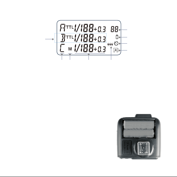
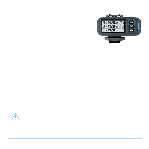
Transmitter Panel
CH
D
C B A F
A. Output Settings per Group in the M mode;
FEC Settings per Group in the TTL mode
B. Mode Settings
C. Group
D. Currently Selected Group (method 2)
E. Channel Settings
F. Multi Mode Icon
G. Synchronization Delay Setting Icon w
H. Low Battery Indicator
I. Single Contact Mode Icon
Installing Batteries
Slide the battery compartment lid of the transmitter.
Insert two AA batteries (sold separately) as indicated.
Low Battery Indicator
When the battery power gets too low for a stable
signal (<2.4V), the battery warning lamp blinks quickly.
Please replace both batteries of the same type and
strength, as low power leads to misres and diminished range.
E
H
G
I
5
Page 6

USING THE FLASH TRIGGER (NON-TTL)
The ash trigger features the following functions:
1. As a Wireless Flash Trigger
1.1 Mount the transmitter on camera hotshoe and turn it on before turning
on the camera.
1.2 Set the transmitter and the receiver to the same channel by pressing the
Channel Setting Button.
1.3 Press the camera shutter button, and the ash will be triggered
simultaneously. The Status Indicator Lamp of both transmitter and
receiver units turn red.
2. As a Wireless Flash Trigger with PC Sync Socket
2.1 Set the transmitter end and receiver device to the same channel and group.
2.2 The transmitter will control the ash on the receiver end, using the PC Sync
Socket as input by default, bypassing the hotshoe.
2.3 Press the camera shutter. The PC Sync Socket’s signal to control the ash.
2.4 PC Sync Socket can also be set as output. Long press the <CH/OK> Button
of the transmitter until <Fn> is displayed on the panel. Then, set the value
of C.Fn-03 to “OU” by pressing the “GR” button once and rotating the Select
Dial. The PC Sync Socket is in output mode and can trigger an attached
ash though a PC cord.
6
Page 7
SETTING THE TRANSMITTER
• Power Switch
Slide the Power Switch to ON. The LCD screen will turn on. The Status
Indicator Lamp does not illuminate.
Note: In order to avoid power consumption, turn o the transmitter when
not in use.
• AF Assist Beam Power Switch
Slide the power switch to ON, and the AF Assist Beam is activated.
When the camera cannot focus because of darkness, the AF assist beam will
turn on. When the camera can focus, the AF assist beam will turn o.
• Channel Settings
1. Short press the <CH/OK> Button until the channel value blinks.
2. Turn the Select Dial to choose the appropriate channel.
Press the <CH/OK> Button again to conrm the setting.
3. This ash trigger contains 32 channels which can be
changed from 1 to 32. Set the transmitter and the
receiver to the same channel before shooting.
• Mode Settings
1. Short press the <GR> Button and the selected group
will blink. Click to scroll through the modes forwardly
and double-click to scroll through in reverse sequence.
2. Short press the <MODE> Button and the selected
groups’ modes will be changed by the order of TTL/M/-- (-- represents OFF,
the current group will not re).
7
Page 8
• Group POWER / FEC Settings
1. Short press the <GR> Button and the selected
group will blink. Click to scroll through the
modes forwardly and double-click to scroll
through in reverse sequence.
2. Turn the Select Dial to change the power or ash
exposure compensation settings. When the current
group is in the M mode, the power output value is
changeable from 1/1 full power to Min. power* in 0.3 stop increments.
When the current group is in the TTL mode, the FEC amount is changeable
from -3 to 3 in 0.3 stop increments. When the current group is in the -- mode
(ash o), the amounts will not change.
3. Short press the <CH/OK> Button again to conrm the setting.
Min. refers to the minimum power output value that can be set in M/Multi
mode. 1/128 or 1/256 can be set according to C.Fn-05.
The minimum power output value is 1/128 and cannot be set to 1/256 for most
of camera ashes. However, the value can change to 1/256 when using in
combination with stronger Watt-Second ashes such as the Flashpoint
XPLOR600 or Rapid R2.
8
Page 9

• Multi Flash Group ON/OFF Settings
1. Initiate the Multi Flash <MODE> in the C.Fn Custom
Functions (set C.Fn-04 as 1).
2. Short press the <GR> button to select the group.
Click to scroll through the modes forwardly and
double-click to scroll through in reverse sequence.
3. Short press the <MODE> Button to change the mode
of selected group.
4. The current group’s mode will be changed by the order of on/--
(-- represents OFF, which means that the current group will not re ashes
in this mode).
• Multi Flash Parameter Setting
1. Enter into Multi Flash mode before setting
parameters.
2. Press the <MODE> Button to enter Multi Flash
parameter setting menu.
3. The LCD displays the parameters: P (output value),
T (ash times) and H (ash frequency).
4. Short press the <GR> Button to choose the settings. Turn the Select Dial to
change the selected blinking setting values. Continue to press the <GR> Button
until all the amounts are set. Then, short press the <MODE> Button to exit.
As ash times are restricted by ash output value, automatic settings may be forced as
a default value. The times that transmitted to the receiver device are Multi Flash in real
time settings, which are not related to the camera’s shutter speed setting. To guarantee
the successful use of stroboscopic mode, please use the formula below to calculate the
shutter speed. Number of Flashes / Firing Frequency = Shutter Speed
9
Page 10
• Group Settings
1. Long press the <GR> Button to set the exposure values for all the groups in
any mode simultaneously.
2. The settings of the groups which are in the same MODE with the current
group will blink. Turn the Select Dial to change the settings.
3. If the current group is in the M MODE, all the other groups which are in the
M MODE will change their power output value simultaneously. The power
output value is changeable from 1/1 full power to Min. power in 0.3 stop in-
crements, until one of the group’s setting turns to the maximum (1/1) or the
minimum (Min.). If the current group is in the TTL MODE, all the other groups
which are in the M MODE will change their FEC amount simultaneously. The
FEC amount is changeable from -3 to 3 in 0.3 stop increments, until one of
the group’s setting turns to the maximum (3) or the minimum (-3). If the
current group is in the -- MODE (ash o), the amounts will not change.
4. Short press the <GR> Button again to conrm the setting.
• Test Flash
1. Press the <TEST> Trigger Button to test re the ash.
2. Fully press the <TEST> Trigger Button, and the Status
Indicator Lamp turns red and the ash connected to the
receiver should ash.
3. The settings on the transmitter will synchronize
with the receiver.
10
Page 11

• Modeling Lamp Control
Double-click the <CH/OK> Button to power ON/OFF the linked unit’s
modeling lamp.
• Power Saving Mode
1 The ash trigger will go into standby mode after an inactive period of time.
The LCD panel will turn o.
2 Pressing any of the buttons (<TEST> fully pressed/<CH>/<GR>/<MODE>)
can wake up the ash trigger. If the transmitter is attached to the camera,
half pressing the shutter can also wake up the system.
3 If the transmitter is set to single contact mode ( is displayed), the system
will not enter the power saving mode.
• C.Fn: Setting Custom Functions
The following table lists the available and unavailable custom functions of this
ash. Note: Some icons will be displayed when setting the relevant custom
functions for clarity.
Custom
Functions No.
C.Fn-00
C.Fn-01
Functions
Synchronization
delay setting
Single contact
mode
Setting Signs
Settings and Description
OFF
00
Master flash synchronization delay N*100 us
1~100
(synchronization delay icon i s displayed.)
OFF
--
ON (The single contact mode set icon is displayed.)
on
It is advisable to set the transmitter to single contact
mode when using it to trigger the flash by PC cord or
through camera's single contact.
11
Page 12

Press the TEST Button to turn on the ash trigger. When the Status Indicator Lamp blinks
two times, the eective remote distance is below 98 feet, and the transmitter and receiver
can communicate normally in this proximity.
12
Page 13

1. Press the <CH/OK> Button for 2 seconds or longer until <Fn> is displayed.
2. Select the custom function number (No).
• Turn the Select Dial to choose the Custom Function No.
3. Change the Setting.
• Press the <GR> Button until the custom function No. blinks.
• Turn the Select Dial to set the desired number. Pressing <GR> button will
conrm the settings.
• Press <MODE> button to exit the C.Fn settings.
Transmitter Setup
• SETTING THE CAMER A
To trigger the R2T-F,
please set camera’s ash mode to TTL ash.
Fujilm menu system ash mode setting:
13
Page 14

• SHOE MOUNT FLASH
The following options are
available when an optional
shoe-mounted ash unit is
attached and turned on.
1. Flash control mode: The ash control mode is selected from the ash unit. This can in
some cases be adjusted from the camera; the options available vary with the ash.
• TTL: TTL mode. Adjust ash compensation(2).
• MULTI: Repeating ash. Compatible shoe-mounted ash units will re multiple times
with each shot.
• (OFF): The ash does not re. Some ash units can be turned o from the camera.
2. Flash compensation/output: The options available vary with ash control mode .
• TTL: Adjust ash compensation (the full value may not be applied if the limits of the ash
control system are exceeded). In the cases of the Fujilm EF-X20, EF-20, and EF-42, the
selected value is added to the value selected with the ash unit.
• MULTI: Adjust ash output (compatible units only).
3. Flash mode (TTL): Choose a ash mode for TTL ash control. The options available vary
wilh the shooting mode (P, S, A, or M) selected.
• TTL AUTO (FLASH AUTO): The ash res only as required; ash level is adjusted
according to subject brightness. A icon displayed when the shutter button is pressed
halfway indicates that the ash will re when the photo is taken.
• Flash TTL (STANDARD): The ash res with every shot, if possible and the ash level
is adjusted according to subject brightness. The ash will not re if not fully recycled
when the shutter is released.
• TTL SLOW (SLOW SYNC.): This mode combines the ash with slow shutter speeds
when photographing portrait subjects against a backdrop of night scenery. The ash will
not re if not fully recycled when the shutter is released.
14
Page 15

4. Sync: Control ash timing.
• (1ST CURTAIN): The ash res immediately after the shutter opens.
• (2ND CURTAIN): The ash res immediately before the shutter closes.
• (AUTO FP(HSS): High-speed sync (compatible units only). The camera automatically
engages front-curtain high-speed sync at shutter speeds faster than the ash sync speed.
Equivalent to 1ST CURTAIN when MULTI is selected for ash control mode.
5. Zoom: The angle of illumination (ash coverage) for units that support ash zoom.
Some units allow the adjustment to be made from the camera. If AUTO is selected, zoom
will automatically be adjusted to match coverage to lens focal length.
6. Lighting: If the unit supports this feature, choose from the options below.
• (FLASH POWER PR IORITY): Gain range by slightly reducing coverage.
• (STANDARD): Match coverage to picture angle.
• (EVEN COVERAGE PRIORITY): Slightly increase in coverage for more even lighting.
7. LED light: Choose how the built-in LED light functions during still photography
(compatible units only). It can function as a catch light ( /CATCH LIGHT), as an AF-assist
illuminator (AF/AF ASSIST), or as both a catch light and an AF-ASSIST illuminator
( /AF ASSIST+CATCHLIGHT). Choose OFF to disable the LED during photography.
8. Number of ashes: Choose the number of times the ash res each time the shutter is
released in MULTI mode.
• Frequency: Choose the frequency at which the ash res in MULTI mode.
NOTE: The full value may not be applied if limits of ash control system are exceeded.
15
Page 16

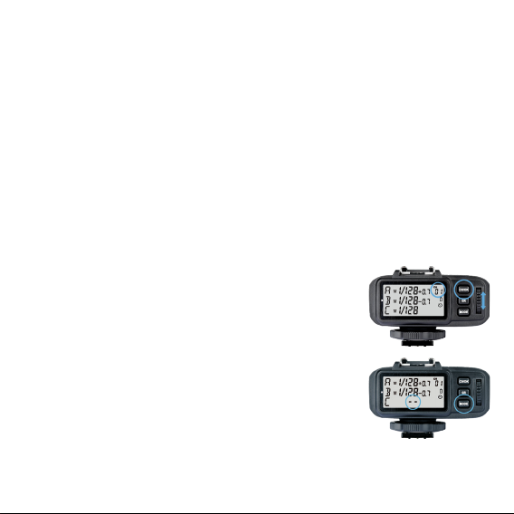
Selecting the Operation Method Options
Press the <CH/OK> Button for 5 seconds to switch the operation methods
(Method 1/Method 2).
R2T-F Operation Method 1 (by default)
16
TTL/M Mode
Button
CH/
OK
GR
MODE
Select Dial
Operation
Short press
Double-click
Long press for 2 seconds
Long press for 5 seconds
Short press
Double-click
Long press for 2 seconds
Short press
Status
Normal
Set the channel
Set the group
Function
(under normal status) Enter CH settings;
(under settings)Confirm and back to normal status
Control the ON/OFF of modeling flash
Enter C.Fn custom settings
Switch the Operation Methods (Method 1/Method 2)
Select the group downwardly
Select the group upwardly
Select all the group
Switch the flash mode of the group (TTL/M/OFF)
Function
No (3 groups)/Turning(5 groups)
Adjust the channel amount
Adjust the group's POWER/FEC amount
Page 17

17
Page 18

R2T-F Operation Method 2
18
TTL/M Mode
Button
CH/
OK
GR
MODE
Select Dial
Operation
Short press
Double-click
Long press for 2 seconds
Long press for 5 seconds
Short press
Long press for 2 seconds
Short press
Status
Normal
Set the channel
Set the group
Function
(under normal status) Enter CH settings;
(under settings) Confirm and back to normal status
Control the ON/OFF of modeling flash
Enter C.Fn custom settings
Switch the Operation Methods (Method 1/Method 2)
Set POWER/FEC amount
Select all the group
(under normal status) Switch the < Group>mode
(TTL/M/OFF)
Function
Set < Group>
Set the channel amount
Adjust the group’s POWER/FEC amount
Page 19

Multi Mode (C.FN-04-on)
Button
CH/OK
GR
MODE
Select Dial
OK
Operation
Short press
Double-click
Long press for 2 seconds
Long press for 5 seconds
Short press
Short press
Long press for 2 seconds
Status
Normal
Set the channel
Set the power
Set the flash times
Set the flash frequency
Function
(under normal status) Enter CH settings;
(under settings) Confirm and back to normal status
Control the ON/OFF of modeling flash
Enter C.Fn custom settings
Switch the Operation Methods (Method 1/Method 2)
(under PTH status) Set power/times /hz
(under normal)Control the < Group>'s ON/OFF
(under PTH status) Back to normal status
Enter PTH status (P-power, T-times, and H-hz)
Function
No (3 groups)/Turning(5 groups)
Adjust the channel amount
Adjust the power amount
Adjust the times amount
Adjust the frequency amount
19
Page 20

Troubleshooting
1. Unable to trigger ash or camera shutter: Make sure batteries are installed
correctly and Power Switch is turned on. Check if the transmitter and the
receiver are set to the same channel, if the hotshoe mount or connection cable
is well connected, or if the ash triggers are set to the correct mode.
2. Camera shoots but does not focus. Check if the focus mode of the camera or
lens is set to MF, indicating Manual focus. If so, set it to AF, Auto Focus.
3. Signal disturbance or shooting interference. Change a dierent channel on the
devices.
4. Operating distance limited or ash misring: Check if batteries are exhausted.
Maintaining your Radios
• Avoid sudden impact. The device may fail to work after strong shocks, impacts,
or excess stress.
• Keep dry. The product isn’t water-proof. Malfunction, rust, and corrosion may
occur and cause irreparable damage if soaked in water or exposed to high
humidity.
• Avoid sudden temperature changes. Condensation occurs due to sudden
temperature changes such as moving out of a building with higher temperature
and humidity to a much cooler outdoor environment. Please put the radio in a
pouch or plastic bag beforehand.
• Keep away from strong magnetic eld. The strong static of magnetic eld
produced by devices such as radio transmitters leads to malfunction.
20
Page 21

Technical Data
Model
Compatible Cameras
Builted-in remote system
Modulation mode
Power supply
Exposure Control
Manual flash
TTL autoflash
Multi flash
TTL Control
High-speed sync
Flash exposure compensation
Flash exposure lock
Focus assist
Second curtain sync
Wireless Flash
Controllable slave group
Transmission range (approx.)
Channel
R2T-F
Fujilm cameras
Support for the cameras that have PC sync socket.
2.4G Wireless transmission
MSK
2 AA Batteries
Yes
TTL
Yes
Yes
Yes, ±3 stops in 1/3 stop increments
Yes
Manual open
Yes (Setting on the camera)
Max. 5 groups (A/B/C/D/E)
>328 feet / 100 meters
32
21
Page 22

Model
Others
Synchronization delay set
Beep
Modeling flash
ZOOM setting
Output interface
Firmware upgrade
Memory function
Dimension/Weight for Transmitter
R2T-F
Yes (0~10ms,use 100us as the unit)
ON/OFF
ON/OFF
Adjust the flash's focal length through the transmitter
Transmitter: use a PC cord to input and output
Use the Micro USB port to upgrade
Settings will be stored for 2 seconds after last operation
and recover after a restart
2.8x3.0x2.0” / 72x75x52mm 3.1oz / 90g
Fujilm Compatible Camera Models
FUJIFILM cameras are divided into three categories according to their dierent
controlling methods of TTL features to the camera ash:
A: X-Pro2, X-T20,
X-T2, X-T1
B: X-Pro1, X-T10,
X-E1, X-A 3
C: X100F, X100T
Note: 1. X100T does not have second curtain sync (REAR) function. 2.The AF assist beam will light up when the
shutter is at low speed (<1/200s). This table only lists the tested camera models, not all Fujilm cameras. For
the compatibility of other camera models, a self-test is recommended. Rights to modify this table are retained.
22
Page 23

ONE YEAR FLASHPOINT LIMITED WARRANTY
Flashpoint warrants to the original purchaser that your Flashpoint R2 Radio Transmitter shall
be free from defects in material and workmanship for the period of one (1) year from the date
of purchase (or delivery as may be required in certain jurisdictions), or thirty (30) days after
replacement, whichever comes later. Flashpoint’s entire liability and your exclusive remedy
for any breach of warranty shall be, at Flashpoint’s option, to repair or replace the hardware,
provided that the hardware is returned to the point of purchase or such other place as Flashpoint
may direct with a copy of the sales receipt or dated itemized receipt. Flashpoint may, at its option,
replace your product, oer to provide a functionally equivalent product, or repair any product
with new, refurbished or used parts as long as such parts are in compliance with the product’s
technical specications. Any replacement hardware product will be warranted for the remainder
of the original warranty period or thirty (30) days, whichever is longer, or for any additional period
of time that may be applicable in your jurisdiction. If the product has been discontinued, the
warranty provider reserves the right to replace it with a model of equivalent quality and function.
This warranty does not cover problems or damage resulting from accident, abuse, misapplication,
or any unauthorized repair, modication or disassembly, improper operation or maintenance,
normal wear and tear, or usage not in accordance with product instructions or connection to
improper voltage supply, use of consumables, such as replacement batteries, not supplied by
Flashpoint, except where such restriction is prohibited by applicable law. Except where prohibited
by applicable law, this warranty is nontransferable and is limited to the original purchaser and the
country in which the product was purchased. This warranty gives you specic legal rights, and you
may also have other rights, including a longer warranty duration that may vary under local laws.
To start a warranty claim contact the Flashpoint Customer Service Department to obtain a return
merchandise authorization (“RMA”) number, and return the defective product to Flashpoint, along
with the RMA number and proof of purchase.
Question about our product line? Need Product Support?
We are proud of our products and celebrate our customers. We are with you, from product
selection to everyday use. Be secure with your purchase and reach us as you need.
Email us: brands@adorama.com Call: 212-647-9300
Address: Adorama Brands, 42 West 18th Street, New York, NY 10011
You can always contact us at BRANDS@ADORAMA.COM for personal technical support.
Our web site contains a wide range of Support and FAQ pages with valuable technical assistance.
Flashpoint is a registered trademark of ADORAMA CAMERA.
© 2017 Adorama Camera, Corp. All Rights Reserved.
23
Page 24

 Loading...