

FlashForge Corporation
Dreamer User Guide | www.FlashForge.com
2
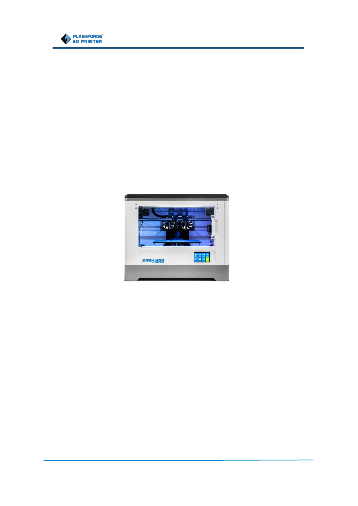
FlashForge Dreamer 3D Pr inter
User Guide
Flashforge Corporation
Dreamer User Guide | www.FlashForge.com
3
This user guide
is suitable for
Dreamer Fir mwar e
Edition
Flashpr int Softwar e
Edition
20171222
3.20.0
Update Date
Update Chapter
Update Content
Dec 23rd, 2017
Ch apter 7 7.3
Add Dr eamer passwor d lock fun ction
Jan 5th, 2018
Ch apter 7 7.3
Mod ify Dr eamer p asswor d lock funct ion:
Add " n eed to enter old passwor d fu nction"
when tur n on /off p asswor d-lock,in which you
can choose to r eset passwor d or tur n on/off
pa sswor d-lock.
Ma r ch,28th ,2019
Ch apter 3
Ch ange the unp acking pictur es
Ma r ch,28th ,2019
Ch apter 8
Add new Chapter 8: Mainten ance and
solution s
V4.0 10.13.2015

Flashforge Corporation
Dreamer User Guide | www.flashforge.com
4
Content
Content................................................................................................................................................. 4
Introduction.......................................................................................................................................... 6
Notice....................................................................................................................................................7
Chapter 1: 3D Printing Technology...................................................................................................10
1.1 Process..................................................................................................................................10
Chapter 2 . About Dreamer................................................................................................................ 12
2.1 About Your Dreamer............................................................................................................12
2.1.1 Main view:.........................................................................................................................12
Chapter 3. Unpacking.........................................................................................................................16
Chapter 4 . Hardware Assembly........................................................................................................ 19
4.1 Mounting the Extruder Set...................................................................................................19
4.2 Installing Filament............................................................................................................... 21
4.3 Plugging in Power Cable&USB Cable................................................................................ 22
4.4 Loading and Unloading Filament........................................................................................ 22
Chapter 5: Build Plate Leveling.........................................................................................................26
Chapter 6: About Software.................................................................................................................29
6.1 Software Installation............................................................................................................ 29
6.2 Exploring FlashPrint............................................................................................................ 29
Chapter 7: Basic Printing................................................................................................................... 54
7.1 Single-Extrusion and Dual-Extrusion Print......................................................................... 54
7.2 Methods of printing..............................................................................................................61
7.3 Printer password lock...........................................................................................................64
Chapter 8: Maintenance and solutions...............................................................................................67
Chapter 9: Supports and Service........................................................................................................70

Flashforge Corporation
Dreamer User Guide | www.flashforge.com
5
Pr eface
Note: Each device must be tested before leaving factory. If there are some residues in
extruder or some tiny scratches on the build tape, it is normal and won’t affect the
printing quality.
On the completion of this User Guide, thanks all FlashForge engineers and the
FlashForge 3D printer users for their unremitting efforts and sincere assistance.
The FlashForge Dreamer User Guide is designed for the Dreamer users to start their
printing journey with FlashForge Dreamer. Even if you are familiar with earlier
FlashForge machines or 3D printing technology, we still recommend that you read
through this guide, as there is lots of important information about the Dreamer for you
to get a better 3D experience.
For a better and more successful printing experience, you can
refer to the following materials:
(1) Quick Star t Guide
Users will find the Quick Start Guide together with the printer accessories. The Quick
Start Guide will help you start your print journey as soon as possible.
(2) Official FlashFor ge Website: http://www.flashforge.com
The official FlashForge website contains the up-to-date information concerning
FlashForge software, firmware, device maintenance and so on. Users are also able to
get the contact information from there.

Dreamer User Guide | www.flashforge.com
6
Intr oduction
The FlashForge Dreamer 3D Printer User Guide contains the information needed
for you to set up and use this device.
This User Guide includes the following parts: Preface, Introduction and
After-sales service.
The Preface section includes resource acquisition channel, the overall framework
of the manual, and the problems that should be paid attention to.
The introduction section contains the presentation of 3D printing technology,
equipment introduction, unpacking and installation of equipment, software installation
and usage.
After-sales section covers how to get the support and help.
·Please read FlashForge Dreamer 3D Printer User Guide carefully before use.
·The User Guide is written based on Windows 7 OS.
·The version of the FlashPrint is the latest.
Flashforge Corporation
Notes
:

Dreamer User Guide | www.flashforge.com
7
Safety Notice
! Notices: Read all the instructions in the manual and familiarize yourself with the
FlashForge Dreamer User Guide before setting-up and using. Failure to comply with
the warning and instructions may result in individual injury, fire, equipment damage or
property damage.
PLEASE STRICTLY FOLLOW ALL THE SAFETY WARNINGS AND NOTICE
BELOW ALL THE TIME.
· Wor k Envir onment Safety
① Keep your work place tidy.
② Do not operate Dreamer in the presence of flammable liquids, gases or dust.
③ Dreamer should be placed out of children and untrained people's reach.
· Electr icity Safety
① Always use the Dreamer with a properly grounded outlet. Do not refit Dreamer’s
plug.
② Do not use Dreamer in damp or wet locations. Do not expose Dreamer to burning
sun.
③ In case of device damage, please use the power supply provided by FlashForge.
④ Avoid using the device during an thunderstorm.
⑤ In case of uncertain accident, please unplug the device if you do not use it for long
time.
Flashforge Corporation
Notice

Flashforge Corporation
Dreamer User Guide | www.flashforge.com
8
·Personal Safety
① Do not touch the nozzle and build plate during printing.
② Do not touch the nozzle after finishing printing.
③ Dress properly. Do not wear loose clothing or jewelry. Keep your hair, clothing
and gloves away from moving parts.
④ Do not operate the device while you are tired or under the influence of drugs,
alcohol or medication.
· Cautions
① Do not leave the device unattended for long.
② Do not make any modifications to the device.
③ To lower the build plate before loading/unloading filament. (The distance between
the nozzle and build plate should be kept for at least 50mm)
④ Operate the device in a well-ventilated environment.
⑤ Never use the device for illegal activities.
⑥ Never use the device to make any food storage vessels.
⑦ Never use the device to make any electrical appliance.
⑧ Never put the model into your mouth.
⑨ Do not remove the models with force.
· Envir onment Requir ements
Temperature: RT 15-30℃
Moisture: 20%-70%
· Place Requir ements
The device must be placed in a dry and ventilated environment. The distances of the

Flashforge Corporation
Dreamer User Guide | www.flashforge.com
9
left, right and back side space should be at least 20cm, and the distance of the front
side space should be at least 35cm.
· Filament Requir ements
Do not abuse the filament. Please make sure you use the FlashForge filament or the
filament from the brands recommened by FlashForge.
· Filament Stor age
All polymers will be degraded with time. Do not unpack until filament is needed.
Filament should be stored in clean and dry conditions.
All the information in this document is subject to any amendment or change without
the official authorization from FlashForge.
FLASHFORGE CORPORATION MAKES NO WARRANTY OF ANY KIND
WITH REGARD TO THIS DOCUMENT, INCLUDING, BUT NOT LIMITED TO,
THE IMPLIED WARRATIES OF MERCHANTABILITY AND FITNESS FOR A
PARTICULAR PURPOSE.
FlashForge shall not be liable for errors contained herein for incidental consequential
damages in connection with furnishing, performance or use of this material
This document contains proprietary information protected by copyright.
Legal Notice
Copyright © 2017 FlashForge Corp. All Rights Reserved

Flashforge Corporation
Dreamer User Guide | www.flashforge.com
10
3D printing refers to transforming three-dimensional models into physical objects that
you can hold and touch. It is also called additive manufacturing because the 3D model
is created by “adding” layers upon layers of material until the object is fully formed.
Fused Filament Fabrication (FFF) is the most common method of 3D printing. It is
also the method that the Dreamer uses. It works by melting plastic material called
filament onto a print surface in high temperature. The filament solidifies after it cools
down, which happens instantaneously after it is extruded from the nozzle. 3D objects
are formed with the filament laying down multiple layers.
1.) Make or download a 3D model
2.) Slice and export the 3D model
3.) Build the 3D model
Currently, there are three ways of making a 3D model.
·Designing Fr om Scratch You can use free CAD (computer-aided design) software
such as 3DTADA, AutoCAD, SolidWorks, Pro-E, and our own software Happy 3D,
which is suitable for the beginners, to design your own 3D model.
·3D Scanner s An alternative method to making a 3D model is to scan an object. 3D
scanners work by digitizing a physical object, collecting its geometric data, and saving
it to a file on your PC. There are also apps that can turn a mobile device into a 3D
Chapter 1: 3D Printing Technology
1.1 Pr ocess
3D printing involves three steps:
1.1.1 Make a 3D Model

Dreamer User Guide | www.flashforge.com
11
scanner.
·Fr om the Cloud The most popular way of obtaining a 3D model is to download it
from websites that allow users to upload 3D models that they designed.
E.g. www. thingiverse.com
1.1.2 Slice and Export the 3D Model
Slice software is the software that prepares 3D models for printing and turns them into
instructions for the 3D printers. FlashPrint is the slicing software used for the
FlashForge Dreamer.
Using FlashPrint, you can prepare .stl files to be .g or .gx files for printing. Then the
files can be transferred to your Dreamer via USB cable, USB stick or WiFi.
1.1.3 Build the 3D Model
Once the output file has been transferred to your Dreamer, it will start to turn the 3D
model into a physical object by laying down layers of filament.
Flashforge Corporation
Dreamer User Guide | www.flashforge.com
12
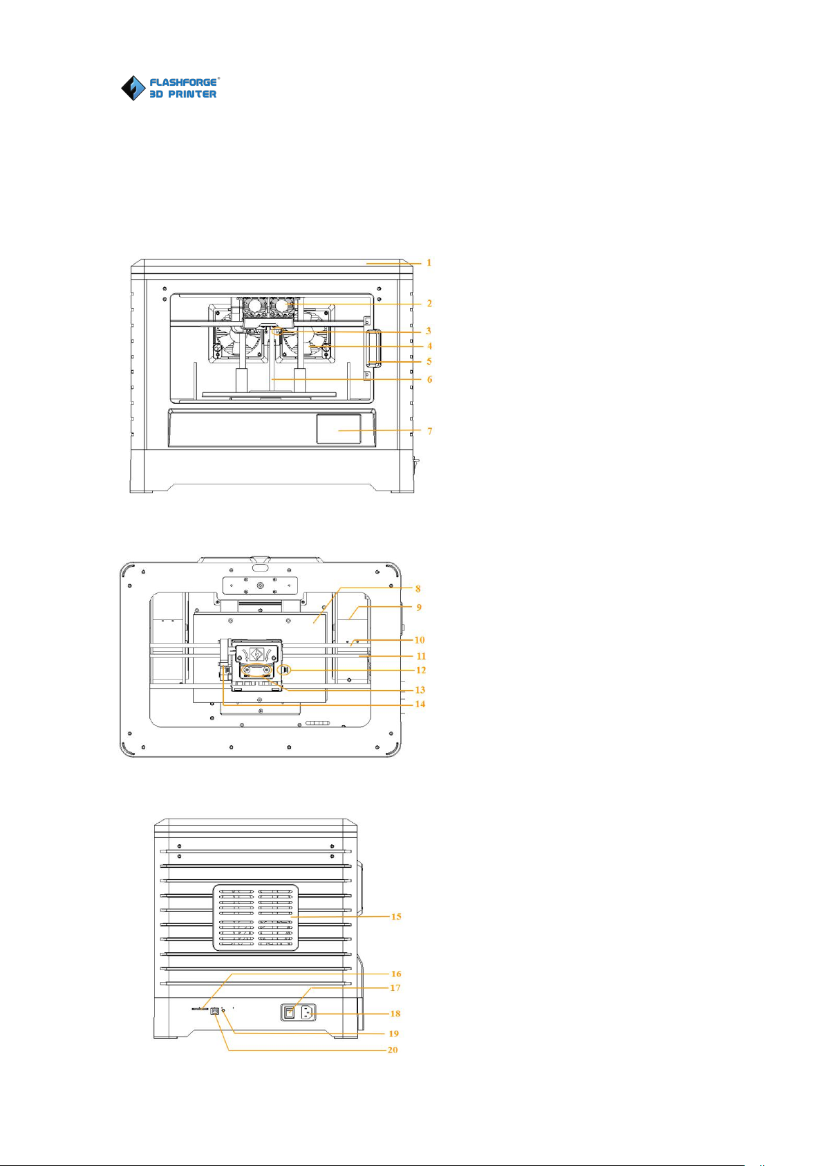
Chapter 2 . About Dreamer
Top view
:
Left view
:
1. Lid
2. Cooling fan
3. Nozzle
4. Ventilating fan
5. Front door
6. Z axis guide rod
7. Touch screen
8. Build plate
9. Filament slot
10. X axis guide rod
11. Timing belt
12. Spring presser
13. Filament intake
14. Turbofan
15. Side panel
16. SD card slot
17. Power switch
18. Power input
19. Reset button
20. USB cable input
2.1 About Your Dr eamer
2.1.1 Main view:
Flashforge Corporation

Flashforge Corporation
Dreamer User Guide | www.flashforge.com
13
Filament*2 Power Cable USB Cable Side Panel*2
Turbofan Baffle Tool Bag Build Tape Quick State Guide
Tweezers SD Card Leveling Card Screwdriver
Scraper Screw Box Carving Knife Stamping Wrench
Unclogging Pin Tool Allen wrench Grease
2.1.2 Accessory Box

Dreamer User Guide | www.flashforge.com
14
2.1.3 Ter ms
Build Plate
The surface on which the Dreamer builds an object.
Build Tape
The blue tape that covers Dreamer’s build plate so that
the object can adhere to the build plate well.
Build Volume
The three dimensional amount of space that an object
will use once it is completed. The largest build volume
of Dreamer is 230*150*140mm.
Leveling Knobs
Knobs under the build platform that are used for
adjusting the distance between the nozzle and build
plate.
Extruder
The device that draws the filament from the spool,
melts it and pushes it through a nozzle onto the build
plate.
Nozzle
Also called “print head”, which located at the bottom of
the extruder where heated filament is squeezed out.
Cooling Fan
To cool the outer assembly of the extruder and gear
motor.
Filament Intake
An opening located at the top of the extruder .
Filament Guide Tube
A plastic piece that guides the filament from the
filament box to the filament intake.
Unclogging Pin Tool
A tool that used for cleaning and unclogging the
extruder.
Stamping Wrench
A tool that used for seizing the nozzle’s metal cube.
Flashforge Corporation

Dreamer User Guide | www.flashforge.com
15
2.1.4 Reference
Name
Dreamer
Number of Extruder
2
Print Technology
Fused Filament Fabrication(FFF)
Screen
3.5’’ color IPS Touch Screen
Print Accuracy
±0.1-0.2mm
Positioning Accuracy
Z axis 0.0025mm; XY axis 0.011mm
Layer Resolution
0.05-0.4mm
Build Volume
230*150*140mm
Nozzle Diameter
0.4mm
Build Speed
10~200mm/s
Maximum Extruder
Temperature
240℃
Filament Diameter
1.75mm(±0.07)
Filament Types
ABS/PLA/Conductive PLA/Flexible Filament
Software
FlashPrint
Support Formats
3MF/STL/OBJ/FPP/BMP/PNG/JPG/JPEG;
GX/G
System
Win xp/Vista/7/8/10、Mac OS、Linux
AC Input
100-240V~/4.5A-2.5A
Device Size
485*344*382(402)mm
Net Weight
10.7Kg
Connectivity
USB cable, SD card, WiFi
Flashforge Corporation
Flashforge Corporation
Dreamer User Guide | www.flashforge.com
16
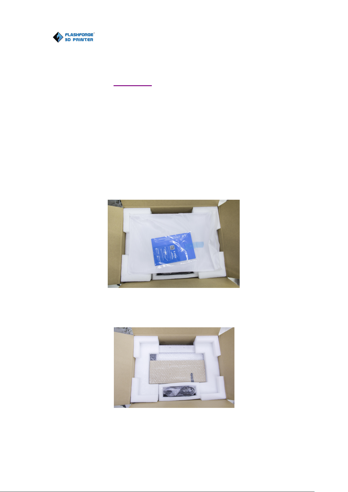
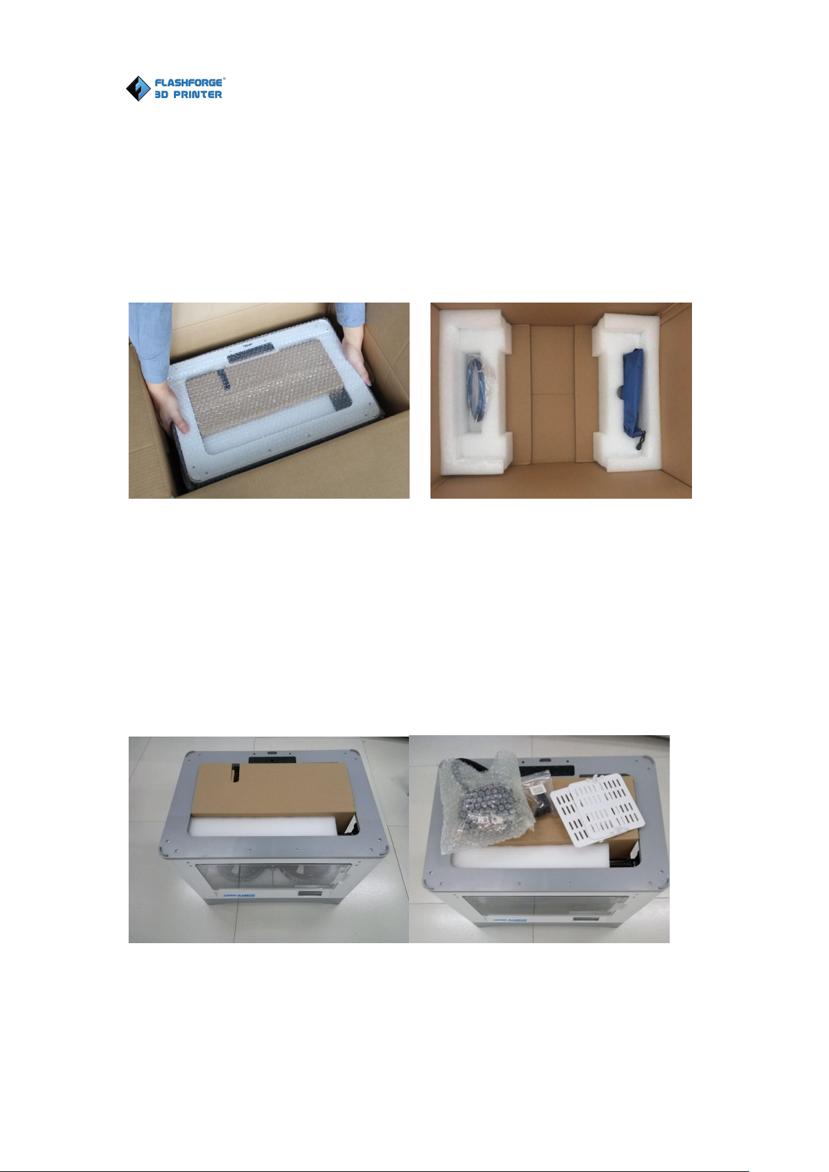
This chapter will present you the whole unpacking procedure of Dreamer 3D
printer.(Note: Make sure you r ead the whole unpacking guide)
1.
(3-1)Put Dreamer package on the clean, tidy workbench, using a knife to cut the
3-1
2. (3-2)Remove the top protective foam pieces, which also houses the Dreamer’s
Chapter 3. Unpacking
(Reference video:Unpacking)
tape, then you can see a quick start guide, a leveling card and two build tapes. Please
read the quick start guide first and start you 3D printing journey with your Dreamer
3D printer.
lid and put them aside. The Dreamer unit and a power cable will be exposed.
3-2
Flashforge Corporation
Dreamer User Guide | www.flashforge.com
17
3.
(
3-3)Firmly grasp the two side handles of FlashForge Dreamer. Lift it out of the
4.(3-4)You can find an accessory box on top of Dreamer, which houses the extruder
3-4
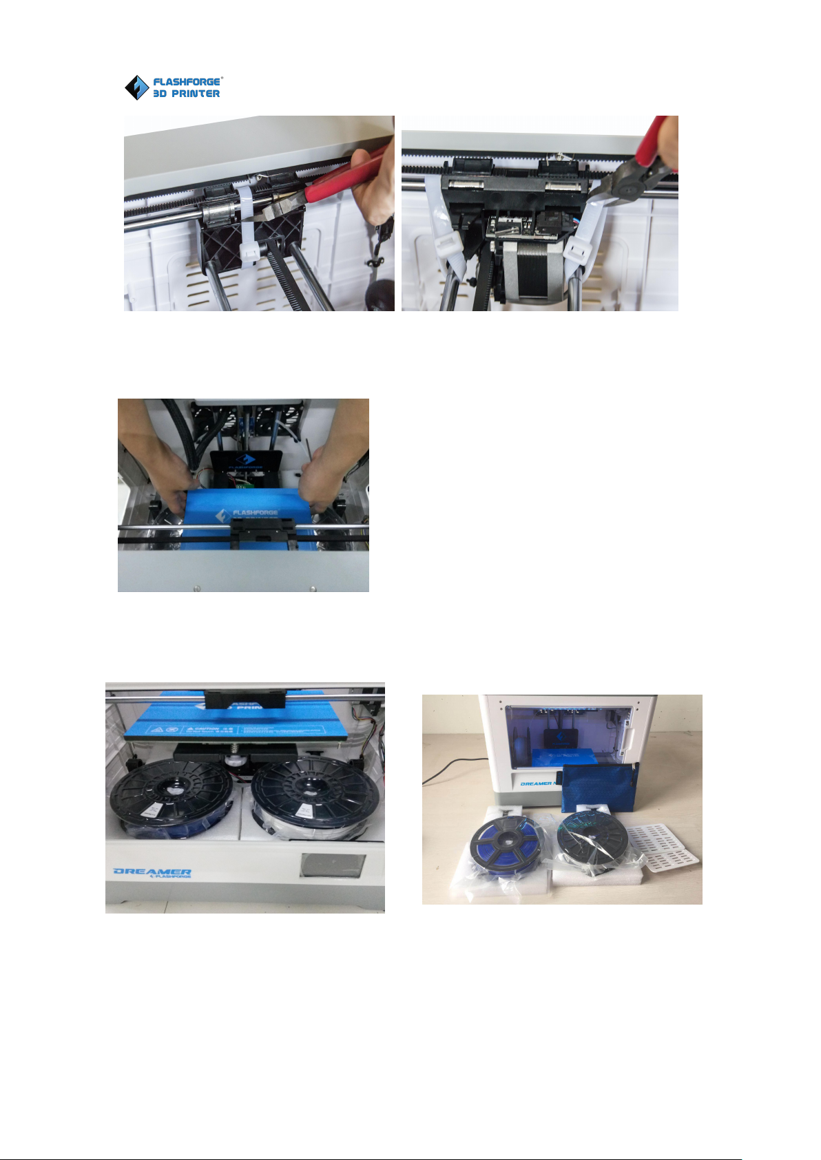
5.Use scissors to remove ties
box and place it on a stable surface. Then you will see the Tool Box and USB cable
in the shipping box. In the Tool Box, you can find a Car ving Knife, a Scr aper , a
bag of Gr ease, Tweezer s and a Scr ew Box, which contains a SD car d and some
screws, Wr enches.
3-3
set. Remove the box and the foam sheet from the Dreamer, and gently lay the extruder
set on the Dreamer build plate.
Inside the accessory box, you will find a dual-extr uder , a tur bofan baffle, and two
pieces of r emovable side panels.
Dreamer User Guide | www.flashforge.com
18
3-5 3-6
7. (3-7) Elevate the build plate up carefully.
3-8 3-9
(3-9)You’ve finished unpacking your Dreamer. Next we will move on to the hardware
assembly.
Flashforge Corporation
3-7
(3-8)Take out the two filament carefully which is under the build plate.
Flashforge Corporation
Dreamer User Guide | www.flashforge.com
19
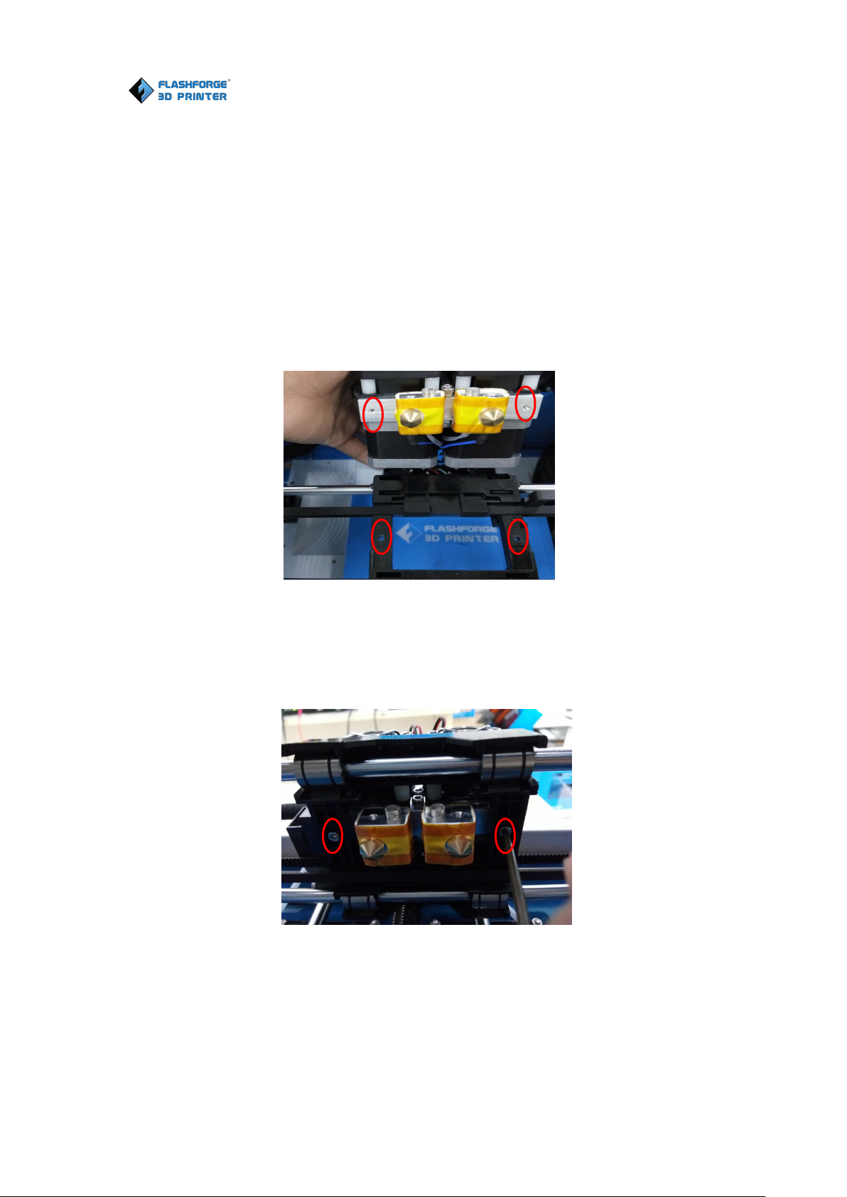
(4-1) Lay the extruder module on the top of the extruder support with the two extruder
fans facing the front.
(4-2) Fix the extruder module onto the extruder support with two M3*12 screws from
the bottom up.
4-2
Chapter 4 . Har dwar e Assembly
The Dreamer comes pre-assembled and is almost ready-to-print (ARP). All you need
to do is to mount the extruder set, and install the filament. It will only take 5 to 10
minutes to start up the Dreamer and prepare for your first 3D print!
4.1 Mounting the Extr uder Set
4-1
Flashforge Corporation
Dreamer User Guide | www.flashforge.com
20
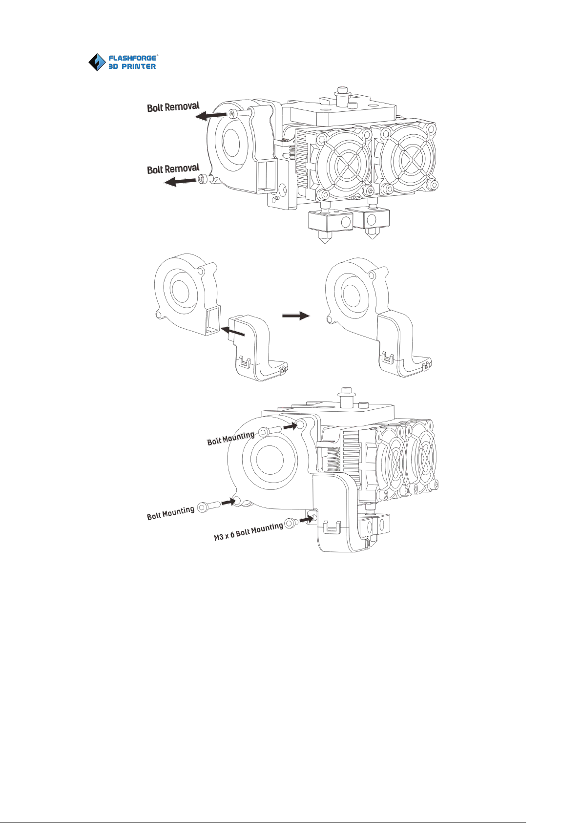
4-3
(4-3) Use the M2.5 Allen Wrench to unscrew two turbofan bolts. Take the turbofan
baffle from the extruder’s accessory kit. Install the turbofan baffle to the turbofan.
Align the bump on the turbofan seat to the hole in turbofan sub-assembly. Place the
turbofan sub-assembly besides the turbofan seat. Insert the bump on the turbofan seat
to the turbofan sub-assembly. Screw the two bolts in. Take a M3 * 6 bolt from the
extruder’s accessory kit and complete installation.
Dreamer User Guide | www.flashforge.com
21
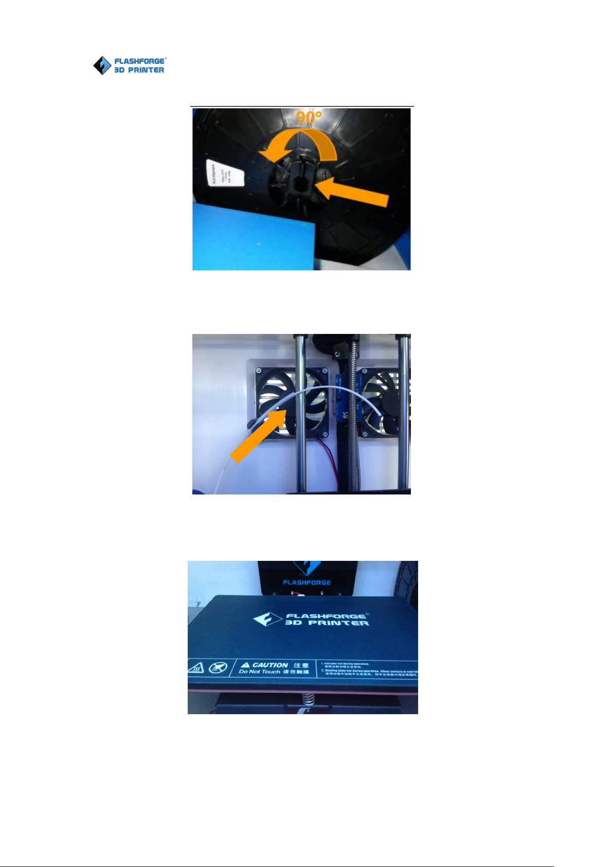
4.2 Installing Filament
(4-4) Lock the filament in place with the filament spool holder and turn the scroll
roller counter-clockwise.
(4-5) Insert the filament through the filament guide tube. Attach the guide tube into
the two filament guide tube buckles.
(4-6) Stick the build tape to the build plate after installing filament, as picture shows.
4-4
4-6
Flashforge Corporation
4-5
Flashforge Corporation
Dreamer User Guide | www.flashforge.com
22
Filament must be passed through the extruder and into the heating tube in order to be
melted. In this user guide, we will demonstrate loading and unloading filament with
the left extruder.
4-7
4-8
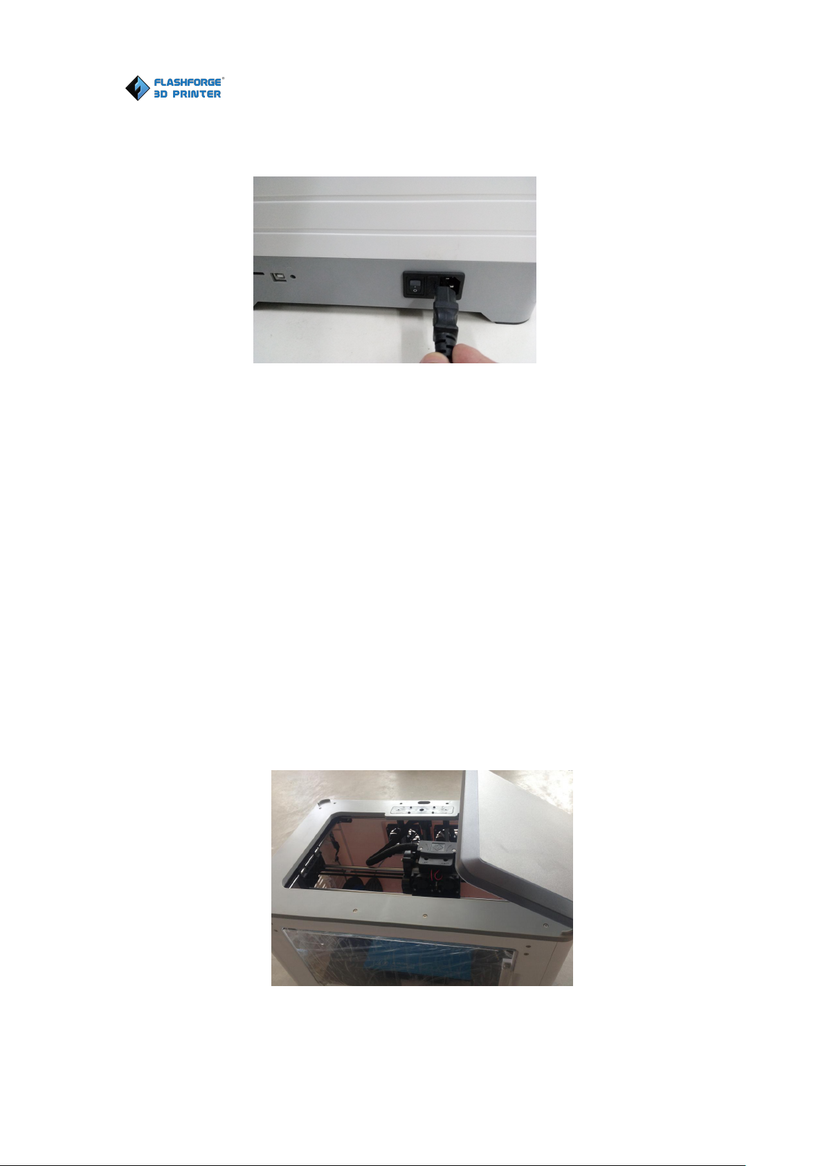
4.3 Plugging in Power Cable&USB Cable
(4-7) Locate the power cable, and plug it into the Dreamer.
Optional: Locate the USB cable and plug one end into the Dreamer and the other into
your computer. The Dreamer supports USB connectivity.
4.4 Loading and Unloading Filament
Loading filament:
(4-8) Remove the lid of the Dreamer

Dreamer User Guide | www.flashforge.com
23
4-9
(4-9) Tap [Tool] in the homepage.
(4-10) Tap [Filament]-[Load Left].
(4-11)Wait for the extruder to heat up to the operating temperature. The extruder will
alert you once it is at the operating temperature. Load the filament by inserting it into
the extruder at an upright angle.
4-10
Flashforge Corporation
4-11

Dreamer User Guide | www.flashforge.com
24
(4-12) Filament will start to be extruded out of the nozzle. Continue loading to ensure
that the filament is being extruded in a straight line. Then tap [Done] to finish
loading.
Unloading filament:
(4-14) Tap [Tool] in the homepage.
4-12
Flashforge Corporation
(4-13) Remove the lid of the Dreamer
4-13
4-14

Dreamer User Guide | www.flashforge.com
25
(4-15) Tap [Filament]-[Unload Left].
4-16
(4-16)Wait for the extruder to heat up to the operating temperature. The extruder will
alert you once it is at the operating temperature. (4-17)Press the spring presser, press
down the filament for about three seconds and gently pull the filament out. Then tap
[Done] to finish unloading.
4-15
Flashforge Corporation
4-17

Flashforge Corporation
Dreamer User Guide | www.flashforge.com
26
A correctly leveled build plate is almost a guarantee for a high-quality 3D object.
When there are some troubles in printing process, you should check whether the build
plate is leveled or not firstly. A general rule of thumb is to leave a gap with the
thickness of a piece of paper. However, for printing finer objects (150 micron and
lower), please use a feeler gauge to level the build plate as it requires a lesser gap
between the nozzle and the build plate.
The Dreamer utilizes a three-point leveling system for its build plate. At the bottom of
the build plate, there is one spring-loaded knob in the front and two in the back.
Tightening the screw will create a bigger gap between the build plate and the nozzle
while loosening it will create lesser gap.
Chapter 5: Build Plate Leveling
5-1
1. (5-1)From the main menu, tap [Tool]-[Level]. The extruder and the build plate
will begin to move to the starting position.

Dreamer User Guide | www.flashforge.com
27
5-2
2. (5-2)Take out the leveling card.
3. ( 5-3 ) Once the extruder and build plate stop moving, slide the piece of paper
continuously back and forth between the nozzle and the build plate. And
simultaneously adjust the knob until the paper causes a slight friction.
4. (5-4)Tap [NEXT] and wait for the extruder to move to the second position. Slide
the paper back and forth again, and adjust the screw to create the same amount of
Flashforge Corporation
5-3
5-4

Flashforge Corporation
Dreamer User Guide | www.flashforge.com
28
5-5
friction as the previous step.
5. (5-5)Tap [NEXT] again and repeat the same leveling process.
7. (5-7)Tap [FINISH] once you have finished this.
5-6
6. (5-6)Tap [NEXT]. The nozzle will move to the center of the build plate. Slide the
paper through to make sure there is a slight friction. Slowly adjust all the screws by
the same amount if there is no friction or too much friction.
5-7

Dreamer User Guide | www.flashforge.com
29
Chapter 6: About Softwar e
This chapter talks about the basic function of FlashPrint. For more information about
advanced function, you can browse our website http://www.FlashForge.com.
6.1.1 Software Acquisition
Method 1: To get the installation package from the SD Card in the toolkit.
Method 2: Open the link below to download the installation package:
http://www.FlashForge.com
Suppor t---Downloads---FlashPr int---Choose the softwar e ver sion---Download
1. Decompress the zipped file or start the installation program, and then install the
software according to the direction.
2. Start the software with the start menu shortcut or by clicking the software icon.(See
6-1)
Note! After starting FlashPrint, you need to select the target machine type first.
When you start FlashPrint, a dialog box will pop up. Just need to select FlashForge
25
6.1 Softwar e Installation
Flashforge Corporation
6.1.2 Software Installation and Star t-up
6-1
6.2 Explor ing FlashPr int
6. 2.1 Machine Type Selection

Dreamer User Guide | www.flashforge.com
30
Dreamer in the machine type list and click [OK]. You can also change the machine
type via clicking [Pr int]--[Machine type]. Please see graphic 6-2:
6-2
6.2.2 FlashPr int Menus
6-3
Flashforge Corporation

Flashforge Corporation
Dreamer User Guide | www.flashforge.com
31
You can load a model file or Gcode file into your FlashPrint by the following six
methods:
Method 1: Click the [Load icon on the main interface. Then select the object file.
Method 2: Select the file for loading and drag the file to the main interface of the
software.
Method 3: Click [File]--[Load File]. Then select the object file for loading.
Load files.
Enter the support edit mode
View FlashPrint home screen from one of six viewing angles.
Move model around on XY-axis; shift+click to move along Z axis
Turn and rotate your model
Scaling the size of your object
Cut the model into several parts
Print it directly with your Dreamer or export to SD card.
Select right or left extruder you want to print with.
6.2.3 Loading

Flashforge Corporation
Dreamer User Guide | www.flashforge.com
32
Method 4: Click [File]--[Examples] to load the example files
Method 5: Click [File]--[Recent Files] to load the files opened recently.
Method 6: Select and drag the target file to the icon of FlashPrint.
Note: 3D models can be stored as .STL, .OBJ , .3MF and .FPP file and support edit
by FlashPrint.
Gener ating Rilievo
Load a .png, .jpg, .jpeg or .bmp picture file into the FlashPrint. And the following
dialogue box(6-4) will pop up. The setting box includes settings for shape, mode,
maximum thickness, base thickness, bottom thickness, width, height, top diameter and
bottom diameter.
Shape: including plane, tube, canister and lamp.
Mode: including “darker is higher” and “lighter is higher”.
Maximum thickness: Z value of the model
Base thickness: The minimum raft thickness and the default value is 0.5mm
Width: X value of the model
Depth: Y value of the model
Bottom thickness: For tube, canister, lamp and seal to set up bottom thickness
Top diameter : For tube, canister, lamp and seal to set up the top diameter
Bottom diameter : For tube, canister, lamp and seal to set up the bottom diameter
6-4

Dreamer User Guide | www.flashforge.com
33
Plane 6-5
Flashforge Corporation
Tube 6-6
Canister 6-7

Flashforge Corporation
Dreamer User Guide | www.flashforge.com
34
Lamp 6-8
Seal 6-9
6.2.4 Views
① Changing views
Change model views by moving, rotating, scaling.
● Dr ag

Flashforge Corporation
Dreamer User Guide | www.flashforge.com
35
Click the [View] icon and then you can move the object by the following three
methods:
Method 1: Hold down the left mouse button and drag.
Method 2: Hold down the mouse wheel and scroll up and down.
Method 3: Hold down the Shift key, hold down the right mouse button and drag.
● Rotate
Click the [View] icon and then you can rotate the object by the following two
methods:
Method 1. Hold down the right mouse button and drag.
Method 2. Hold down the Shift key, hold down the left mouse button and drag.
● Scale
Rotate the mouse wheel to enlarge or shrink the build plate.
Allow users to view the object on the build plate. Six views are under the view menu,
that is, bottom view, top view, front view, back view, left view and right view.
Method 1: Click the the [View] button, there are six views in the drop- down list
Method 2: Click the the [Look] icon on the left, click it again and a submenu will
appear with six views for selecting.
③ Reset View
Allow users to reset views by the following two methods:
Method 1: Click the [View] menu and select [Home View]
Method 2: Click the [View] button on the left, click it again and you will see the
viewing options, you can click [Reset].
④ Show Model Outline
② Set View

Flashforge Corporation
Dreamer User Guide | www.flashforge.com
36
Click [View]--[Show Model Outline], it will highlight the yellow border of the
object
⑤ Show Steep Over hang
Click [View]--[Show Steep Over hang]. When the intersection angle between the
model surface and horizontal line is within the overhang threshold value, the surface
has steep overhang and it becomes red in the software. Overhang threshold value
could be set as needed. The default value is 45 degree.
6.2.5 Move
Select the object and move the object by the following two methods:
Method 1: Click the [Move] icon on the left, Long press the left mouse button and
drag to adjust the location of the model in XY direction. Long press the Shift key and
the left mouse button, drag to adjust the location of the model in Z direction. The
distance and the direction of the movement shall be displayed.
Method 2: Click the [Move] button on the left and then enter the distance value.
Click [Reset] to reset distance values.
Note: Users shall click [Center ] and [On Platfor m] after the location adjustment to
ensure the model(s) be within the build area and on the build platform. If a specified
position is needed, only click [On Platfor m].
6.2.6 Rotate
Select the target object and rotate the object by the following two methods:
Method 1: Click the [Rotate] icon on the left and three mutually perpendicular rings
appear around the object. Click one ring and rotate on the present axis, you will see
the rotation angle and direction in the center of circle. In this way, you could make the
model rotate on X/Y/Z axis.

Flashforge Corporation
Dreamer User Guide | www.flashforge.com
37
Method 2: Click the [Rotate] icon on the left, and then enter into rotating angle
values in X/Y/Z axes positioning. Click [Reset] to reset rotating angle values.
6.2.7 Scale
Select the target object and scale the object by the following two methods:
Method 1: Click the [Scale] icon on the left, hold down the left mouse button and
scale the model. The corresponding values will display near the object.
Method 2: Click the [Scale] icon on the left and then enter into scale values in X/Y/Z
axes positioning. Click the [Maximum] button to get largest size possible for building.
Click [Reset] to reset the size of model.
Note: If the [Unifor m Scaling] radio button is clicked, it will scale the model in equal
proportion when changing value in any positioning of the model. Otherwise it will
only change the value of the corresponding positioning.
6.2.8 Cut
Left-click on the model to select it and double-click on the [Cut icon] to set the cut
plane. The direction and position are available for setting.
①Draw with Mouse
②X Plane

Flashforge Corporation
Dreamer User Guide | www.flashforge.com
38
③Y Plane
④Z Plane
6.2.9 Extr uder
(6-10) Choose L/R extruder to print, pitch on the model, click on twice, then you can
set extruder .
6-10

Dreamer User Guide | www.flashforge.com
39
6.2.10 Suppor ts
After loading the model, click [Edit]--[Suppor ts] or click the Suppor ts icon directly,
then you will enter the support edit mode (6-11). Click [Back] to exit when you finish
editing.
6-11
①Suppor t Options
Click the Support Options, an option box will appear, supports options include
“treelike” and “linear”, when choose “treelike”, click [OK], then it will generate
treelike structure; when choose “linear”, click [OK], then it will generate linear
structure; if it is a model with supports, when you choose one of the supports options,
software will judge whether existing supports need to be deleted or not on the basis of
the type of existing support, and will pop up the corresponding prompt to let you
make the choice.
Flashforge Corporation

Flashforge Corporation
Dreamer User Guide | www.flashforge.com
40
6-12
Click the [Auto Suppor ts] button, the software will judge the position where supports
are needed and generate corresponding treelike or linear supports. If it is a model with
supports, the existing supports will be deleted and new supports will be generated.
③ Add Suppor ts
Supports will be deleted once clicking the [Delete] button. Move the cursor to the
② Auto Suppor ts
Supports will be added once clicking the [Add] button. Move the cursor to the
position where supports needed, left-click to choose the starting point of supports,
hold down the left mouse button and drag the mouse, the supports preview will show
up (if support surface doesn’t need support or the support column angle is too large,
the support review will be highlighted).Loosen the left mouse button, if support
column doesn’t meet with model, then support will be generated on origin and
terminal point (the highlighted preview support won’t generate support structure)
④ Clear Suppor ts
Click [Clear Supports], all supports will be deleted. The operation can be repealed
via clicking [Undo] or pressing the shortcut key Ctr l+Z.
⑤ Delete Suppor ts

Dreamer User Guide | www.flashforge.com
41
supports needed deleting, current supports and its subnode support will be highlighted,
click the left mouse button to delete these highlighted support.
6.2.11 Print
6-13
① Pr eview: Choose to enter preview interface or not
② Pr int when slice done: Print or not when slice done
③ Mater ial Right/Left: Choose according to the type of model
④ Suppor ts: When print suspended structure models, support is necessary. Click
[suppor ts] to create support part for the printing.
⑤ Raft: This function will help the model to stick well on the platform.
⑥ Wall: During dual color printing, this function will help to clear the leaking
filament of another extruder.
⑦ Br im: Expand the outline of model’s bottom layers to a Brim which helps anchor
the edges of the model to the plate to avoid warping.
⑧ Resolution :You have three resolution solution (with default setting) to choose
from, high resolution is corresponding with slow printing speed, opposite for the low
resolution. For PLA printing, an extra solution “Hyper” is available.
Flashforge Corporation

Flashforge Corporation
Dreamer User Guide | www.flashforge.com
42
⑨ Mor e options: Click [Mor e options] to set for layer, shell, infill, speed and
temperature. Different resolution solution is corresponding to different defaults, click
[Restor e Defaults] to back to default setting.
●Layer
a. Layer : Layer thickness of the printing model. With a small value, the surface
of the model will be smoother.
b. Fir st Layer Height: This is the first layer of the model, which will affect the
sticking performance between the model and platform. Maximum is 0.4mm, usually
the default is OK.
c. Shell: Contains the outside shell value, capping layer value (under vase pattern,
top solid layer setting is invalid.)
● Per imeter Shells: Maximum is 10
a. Top Solid Layer : Maximum is 30, minimum is 1.
b. Bottom Solid Layer : Maximum is 30, minimum is 1.
● Infill
a. Fill Density means fill rate.
b. Fill Patter n is the pattern of filling shape which effects printing duration.
c. Combine Infill: You can select the layers for combining according to the
layer thickness. The combined thickness should not exceed 0.4mm. “Every N layers”
is for all the infills while “Every N inner layers” is only for inner infills, which
generally can save print time.
6-14

Flashforge Corporation
Dreamer User Guide | www.flashforge.com
43
a. Pr int Speed is the moving speed of the extruder. Generally, the lower speed
(5-7) Click[Edit], then you can add or remove a height.
6.2.12 File Menus
Click [File]--[New Pr oject] can build a blank project. If there is an unsaved
modification on previous project, then it will inform you whether the modification
6-15
● Speed
is, the better print you will get. For PLA printing, 60 is recommended.
b. Tr avel Speed is to control the moving speed of the extruder under
non-printing status during work. For PLA printing, 80 is recommended.
Note: Modify parameters settings to get better prints as different models need
different parameters.
● Temper atur e
Right Extr uder Temper atur e: Recommended extruder temperature is 220℃.
Note: Different temperatures have subtle influences in printing. Please adjust the
temperature according to the condition in order to get a good print.
Platfor m Temper atur e: To set the temperature of Platform.
● Other s
Cooling Fan Contr ol: Set up the time to turn on the cooling fan. You can
pre-set the height and make the cooling fan begin to work at the point.
Pause At Heights: Allow users to pre-set a height in which the print will
suspend automatically. The function usually applied when you want to change the
filament at a certain point.
① New Pr oject

Dreamer User Guide | www.flashforge.com
44
needs to be saved or not. Click [Yes] will save the modification; click [No] will
abandon it. If click [Cancel] or close tool tip, then it will cancel the new project.
② Saving
After finishing the model edit and adjustment, there are two ways below to save all
models in the scene.
Method 1:
Click [File]--[Save Pr oject] in the menu bar to save the file as a project file with the
“.fpp” suffix, all models in the scene (include support) are independent. After
reloading the files, extruder configuration information and model position will be the
same as the configuration during saving.
Method 2:
Click [File]--[Pr efer ences], you can choose language and if needs detecting update
when start.
Flashforge Corporation
6-16
Click on [File]--[Save as...] to save the model as project file .fpp or .stl and .obj.
For .stl and .boj, models are integrated as one (include support part). If load it again,
only the position of the model was saved, not included the printing parameters.
③ Pr efer ences

Flashforge Corporation
Dreamer User Guide | www.flashforge.com
45
6-17
● Language: The software supports multi-languages.
● Font Size: Set the font size.
● Auto layout newly-impor ted model: Set Yes or No.
● Pr inting Window Type: Including Base Mode and Expert Mode.
● Check for Update after star t up: It is used to preset if it is necessary to activate
the online automatic update function, if choose yes, every time when you open
software, it can online detect if it is a new version software, once new version found,
it will reminds users to download and install new version firmware.
6.2.13 Edit Menus
① Undo
Allows users to undo the recent edits by the following two methods:
Method 1: Click [Edit]--[Undo].
Method 2: Press the shortcut Ctr l+Z.
② Redo
Allows users to redo the most recent edit you have undone to your model file by the
following two methods
Method 1: Click [Edit]--[Redo]
Method 2: Press the shortcut Ctr l+Y.
③Empty Undo-stack

Flashforge Corporation
Dreamer User Guide | www.flashforge.com
46
Method 1: Click [Edit]--[Select All].
Select the object and duplicate the object through the following two methods:
Method 1: Click [Edit]--[Duplicate]
Method 2: Press the shortcut Ctr l+D
⑥ Delete
Select the object and delete the object through the following two methods:
Method 1: Click [Edit]--[Delete]
Method 2: Press the shortcut Delete
Click [Edit]--[Auto Layout All] after loading one or more than one models, all
models will be placed automatically as automatic placement rule.
⑧ Repair Models
Click [Edit]--[Repair Models] to repair models.
⑨ Suppor ts
Click [Edit]--[Suppor ts] to enter supports setting interface.
6.2.14 Print Menus
① Connect Machine
You can connect the Dreamer with your PC via a USB cable or WiFi.
To clean up the recorded operating steps so as to release the memory.
④ Select All
By the following two methods, you could select all models in the scene.(When
models are too small to be seen or out of viewing scope, please click [Center ] and
[Scale] buttons to adjust the model.)
Method 2: Press the shortcut Ctr l+A.
⑤ Duplicate
⑦ Auto Layout All

Flashforge Corporation
Dreamer User Guide | www.flashforge.com
47
Note: The machine icon on the bottom right displays the connection status:
Connected
Disconnected
Method 1:Connect Via USB Cable
a. Connect your Dreamer with your PC via an USB cable.
b. Turn on your Dreamer and start FlashPrint.
c. Click [Pr int]--[Connect Machine], then select USB in the [Connection Mode]
option and select machine you want to connect in [Select Machine] option. If you can
not find your machine, click the [Rescan] button to scan your machine and select it.
Finally click [Connect] button to connect to the printer. If you still can not find your
machine after rescan, it means you haven’t installed the driver in the software.
3. A network called “USR-WiFi232-G2” can be found on the list of available
6-20
Method 2: Connect Via WiFi--AP mode
1. Turn on Dreamer.
2. Turn on Wi-Fi on the Dreamer. Tap [Tools]-[Setting]-[WiFi]-[WiFi ON].
networks. Connect to this network.

Flashforge Corporation
Dreamer User Guide | www.flashforge.com
48
4. A connection called “USR-WiFi232-G2” can be found on the list of available
5. Open your Internet browser. Type in “10.10.100.254” and hit [Enter ] on your
keyboard. Enter the username and password to login. The default username and
password are both “admin” The control panel will appear after a successful login.
5. Click on [Wor k Mode] and choose “AP+STA mode” and save it.
6-21
4.Open FlashPrint, click[Pr int]--[Connect Machine]. Under “Connection Mode”,
select Wi-Fi, and enter the “IP Addr ess” as shown on printer touch screen. Then,
click [Connect].
5. If successfully connected, you will see the following red mark.
Method 3: Connect Via WiFi--STA mode
1. Turn on Dreamer.
2. Turn on Wi-Fi on the Dreamer. Tap [Tools]-[Setting]-[WiFi]-[WiFi ON].
networks. Connect to this network.

Flashforge Corporation
Dreamer User Guide | www.flashforge.com
49
!Notice: In STA mode, there may be the risk that Dreamer couldn’t be connected via
WiFi forever, if STA mode is set in error.
6. Click on [STA Setting], enter the corresponding password, save the information
and restart to take effect. Your PC connect the network, which was registed.
Disconnect Dr eamer
Click [Pr int]--[Disconnect] to disconnect your PC and Dreamer.
6-22
7. Open FlashPrint, click[Pr int]--[Connect Machine]. Under “Connection Mode”,
select Wi-Fi, and enter the “IP Addr ess” as shown on printer touch screen. Then,
click [Connect].
8. If successfully connected, you will see the following red mark.
6.2.14 Tool Menus
①Contr ol Panel

Flashforge Corporation
Dreamer User Guide | www.flashforge.com
50
After connecting PC with Dreamer, click [Tools]--[Contr ol Panel] to open the
control panel.
6-23
● J og Contr ols
a. J og Mode:Select the distance that extruder/build plate move a single time (that is,
the distance extruder/build plate move upon your single click).
b. Six blue ar r ow dir ection buttons: Control the move along X/Y/Z axis. X/Y axis
button control extruder move, Z axis button control build plate move. Click X-,
extruder will move leftward a specified distance; Click X+, extruder will move a
specified distance rightward. Click Y-, extruder will move forward a specified
distance; Click Y-, extruder will move backward a specified distance. Click Z-, build
plate will move upward a specified distance; Click Z-, build plate will move
downward a specified distance. (Specified distance refers to the move distance you set
in Jog Mode.
c. Stop: Click the [Stop] button to abort the current movement.
d. XYZ coordinate fr ame on the r ight side: Show the current position of
extruder/build plate.
e. Make Curr ent Position Zer o button: Set the current position of the extruder/build
1
2
345
6

Flashforge Corporation
Dreamer User Guide | www.flashforge.com
51
plate as (0, 0, 0). (NOTE: X, Y, and Z boxes are for display purposes. Changing the
value in the boxes will not affect anything.
f. Center X/Y/Z button: Extruder and build platform will back to the zero (0, 0, 0)
you set last time.
g. X/Y Speed and Z Speed: Set the move speed of extruder/ build platform.
● Limit Switch: In order to protect your Dreamer, three limit switches are equipped
to control the maximum position, and the three limit switches corresponding to X/Y/Z
axis limit switch. It has two statuses:
a. Not Tr igger ed: If the extruder/build plate don’t move to its maximum, X/Y/Z axis
limit switch is not triggered, and shows “Not Tr igger ed”.
b. Tr igger ed: If the extruder/build plate moves to its maximum, X/Y/Z axis limit
switch is triggered, and shows “Tr igger ed”.
● Stepper Motor Contr ols: Allows users to control to stepper motor. Click [Enable],
and lock the motor so it does not allow any movement; click [Disable], and unlock
the motor to be controlled manually.
● LED Color : Allows users to change the LED color of Dreamer.
● Extr uder Contr ols: You can set the value of “Motor Speed (RPM)”, which can
control the rotation speed of filament feeding wheel. The motor rotation time can be
controlled via setting the value of “Extr uder Dur ation”. Generally we suggest the
users choose option of continuous time 60 seconds. The filament must be loaded in
the extruder before motor starts. Ther efor e, do not start r otation oper ation until
the extr uder temper atur e r each the pr inting temper atur e of filament. For PLA
filament, the extruder temperature should reach 220℃, after reaching the extruder
temperature, click the [For war d]/[Rever se] rotation button to control filament load
and filament unload. Furthermore, if you want to stop filament load and unload, you
can click [Stop].

Flashforge Corporation
Dreamer User Guide | www.flashforge.com
52
● Temper atur e Contr ol: Input the temperature you want to get in the left frame,
click [Apply], the printer will automatically heat the corresponding part, the right side
shows the current actual temperature of corresponding part. After start heating, the
below curve of temperature form will start to change, different color correspond with
different parts’ temperatures
② Update Fir mwar e
Every time when you start FlashPrint, it will automatically detect and download the
up-to-date firmware. If any update is available, a dialog box will pop up for reminding
the users to update.
Step 1: Click [Tools]--[Update fir mwar e]. It needs to cut off connection before
updating firmware. If software and printer are already in connection, it will remind
you cutting off the connection. Then choose [Yes] and go on to the next step.
Step 2: Choose corresponding printer type and firmware version and click [OK] in
the firmware updating box. After confirming the printer is in free state, the software
will automatically update the firmware.
6-24
Step 3:Reboot you Dreamer and wait for 4-5 seconds, then you can see the update
process bar. When the update finishes, it will go back to the main interface.
Step 4:Tap [Tools]--[About] to check whether the updated version is right.

Dreamer User Guide | www.flashforge.com
53
③ On Boar d Pr efer ences
When the computer and printer are in connection, click [Tools]--[On Boar d
Pr efer ences], you can check the printer name.
When the computer and printer are in connection state, click [Tools]--[Machine
information], you can check the machine type, machine name and firmware etc.
6.2.15 Help Menus
① Fir st Run Wizar d
② Help Contents:Click [Help]--[Help Contents], you can read the help contents.
③Check for Updates : Click [Help]--[Check for Update] to detect the available
updates online.
④ About FlashPr int : Click [Help]--[About FlashPr int], the software information
box will pop up. The contents include the current software version and copyright
information.
④ Machine infor mation
Flashforge Corporation

Flashforge Corporation
Dreamer User Guide | www.flashforge.com
54
1. Open FlashPr int by double-clicking on the icon.
2. Click on [Load] and choose a .stl file from hard drive.
3. The object will then be shown on the screen.
4. Click on the object and then click on [Extruder ], select【Use Left extr uder 】
*Left extruder will be used for illustration purposes.
5. Now the 3D model is ready to be created.
Chapter 7: Basic Printing
This chapter will provide a step-by-step guide on turning a 3D model into a physical
reality. Before proceeding, it is recommended that you go over prior chapters on
loading/unloading filament, leveling the build plate, and the functions and capabilities
of FlashPrint.
There are two modes of printing: single-extrusion and dual-extrusion. With single
extrusion, you can choose the print head to use for making the print. Dual extrusion is
useful if you want to print dual colors or complex models that require supporting
material.
There are three connection methods in order to print using the Dreamer. All methods,
which include USB, SD card, and Wi-Fi are covered in this chapter.
7.1 Single-Extr usion and Dual-Extr usion Pr int
7.1.1 Single-Extrusion Print

Flashforge Corporation
Dreamer User Guide | www.flashforge.com
55
7.1.2 Dual-Extr usion Pr int
5. Click on the object and then click on [Extr uder ], select [Use left extr uder ]to one
part and select【Use Right Extr uder 】the other part.
6. Now the 3D model is ready to be created.
Pr int
Read the print file from
The local memory card
The SD card
Back
1. Open FlashPr int by double-clicking on the icon.
2. Click [Load] and choose a .stl file from hard drive.
3. The object will then be shown on the screen.
4. Click [Load] and choose another (or the same) file from hard drive.
NOTE: one object is turned to green, that indicates it will be print wit the left
extruder.
Before introducing the connection methods, let me give you a brief introduction of
Dreamer’s interfaces.

Flashforge Corporation
Dreamer User Guide | www.flashforge.com
56
Select the target print file among the list
Pr int: To begin printing
Copy: To copy the files to the local
memory card from the SD card.(No
available [Copy] button for printing
from local memory card )
Delete: To delete the print file
Back
Print interface
Abort: To abort the printing job.
Pause/Resume: To suspend or resume
the print job.
Tools: To change filament and set up
auto shutdown during printing.
Tools in print interface
Filament: To change filament during
printing.
(Note: You need to suspend the
operation first)
WiFi: To turn on the WiFi
Cancel: To end the tool orders and
return to the print interface.

Flashforge Corporation
Dreamer User Guide | www.flashforge.com
57
Pr eheat
Tap the [Pr eheat] button to enter the
preheat interface. Tap the [Star t] button
to heat up to the setting temperature.
The default temperature is 230℃.
Tap the temperature display bar to set
the temperature.
To set the preheat temperature.
Tap [Yes] to save the setting while tap
[No] to cancel the setting.
The picture displays the preheat
interface. It shows the actual
temperature and the target temperature.
Tap the [Stop] button to abort the
preheat job.

Flashforge Corporation
Dreamer User Guide | www.flashforge.com
58
Tool
Tap [Tool] to enter tool options.
Filament: To load/unload the filament.
Level: To adjust the build plate.
Home: To make the X, Y and Z axes
back to the zero point.
Manual: To manually adjust the
positions of X, Y and Z axes.
Setting: To implement relevant function
setups.
Status: To check the real-time status of
the printer.
About: Information about the printer.
Back
Manual adjustment
Y+: The extruder moves to the zero
point, that is, the back of the machine
Y-: The extruder moves to the direction
opposite to the Y+.
X+: The extruder moves to the zero
points, that is, to the right direction
X-: The extruder moves to the direction
opposite to the X+.
Z+: The build plate elevates.
Z-: The build plate descends.
Back

Flashforge Corporation
Dreamer User Guide | www.flashforge.com
59
Tap [Setting] to enter the setting
interface
Language: To set the display language
TP Adjust: Adjust the touch screen
Factor y Reset: Restore factory defaults
Fan on: To turn on/off the fan
WiFi: To turn on/off the WiFi
Update: To update the firmware
Pulley: To choose the pulley type
Enable filament detector : To enable or
disable filament detector.
Back
Language:
User can select corresponding language
as required.
TP Adjust:
To tap the “+” on the touch screen to
adjust the touch screen.

Flashforge Corporation
Dreamer User Guide | www.flashforge.com
60
WiFi:
Tur n on the WiFi: Turn on the WiFi,
release the WiFi hotspot and set the
WiFi on computer
Backg
Pulley:
To select the equipped pulley type.
Status:
It displays the real-time status of the
extruder temperature, the platform
temperature and the internal
temperature.
About:
It displays the basic information about
the device.

Dreamer User Guide | www.flashforge.com
61
7.2 Methods of pr inting
Pr inting from USB
1. Connect Dreamer to the computer with the USB 2.0 cable.
2. Turn on the Dreamer. Make sure the build plate is leveled and filament is loaded
into the left extruder.
3. Select [Pr int] from menu bar, then select [Connect].
4. Click on [Rescan], then [Connect].
5. Now the printer is connected with FlashPrint. A status box at the lower right corner
will show the temperature of both extruders and the platform.
6. Click [Pr int] icon, and a printing options screen will appear. Make sure that
“PLA” is selected under Mater ial Left. Advanced settings can be set under [Mor e
Options] . Check the box “Pr int When Slice Done” and click [OK].
7. Save the file at any location, and the object will start slicing
8. After slicing the object, it will automatically upload the gcode to the Dreamer.
9. After the gcode is done uploading, the printer will go preheating. The Dreamer will
begin printing once it has finished preheating.
Pr inting from SD Car d
1. Click [Pr int], and a printing options screen will show up.
2. Make sure that the “Mater ial Left” is selected as “PLA”. Advanced settings can
be set under [Mor e Options] icon.
3. Click [OK], and save the gcode file in the SD card.
4. FlashPrint will begin slicing the 3D model.
5. After slicing the object, take the SD card out from the computer. Insert it into the
SD card slot onto the Dreamer.
6. Turn on the Dreamer. Make sure the build plate is leveled and filament is loaded on
the left extruder.
Flashforge Corporation

Flashforge Corporation
Dreamer User Guide | www.flashforge.com
62
7. Tap [Pr int] and then tap the middle SD Car d icon.
8. A list of file(s) will show up, tap the file that you would like to print, and tap [Yes].
9. The printer will now enter preheating and will start printing once it finishes
preheating
Pr inting via Wi-Fi
1. Turn on Dreamer. Make sure the build plate is leveled and filament is loaded on the
left extruder
2. Turn on Wi-Fi on the Dreamer. Then tap [Tool]-[Setting]-[WiFi]-[WiFi ON].
3. A connection called “USR-WiFi232-G2” can be found on the list of available
networks. Connect your PC to this network.
4. Open your Internet browser. Type in “10.10.100.254” and tap [Enter ] on your
keyboard. Enter the username and password to login. The default username and
password are both “admin” .The control panel will appear after a successful login.
7-2
5. Click on [Wor k Mode] and choose “AP+STA mode” and save it.
Notice: In STA mode, ther e may be the r isk that Dr eamer couldn’t be connected
via WiFi for ever , if STA mode is set in er r or
6.Click on [STA Setting], select a working network, enter the corresponding

Flashforge Corporation
Dreamer User Guide | www.flashforge.com
63
password, save the information and restart to take effect. Your PC connect the
network, which was registed.
7-3
7. Open FlashPrint, click[Pr int]--[Connect Machine]. Under “Connection Mode”,
select Wi-Fi, and enter the “IP Addr ess” as shown on Dreamer touch screen. Then,
click [Connect].
8. Now the Dreamer is connected with FlashPrint. A status box at the lower right
corner will show the temperature of both extruders and the Platform.
9. In FlashPrint, click [Pr int]. A printing options screen will appear. Make sure that
“PLA” is selected under “Mater ial Left.” Advanced settings can be set by clicking
on [Mor e Options]. Check the box of “Pr int When Slice Done”, and click [OK].
10. Save the file at any location, and the object will start slicing. After the object is
done slicing, it will automatically upload the gcode to the Dreamer. After the gcode is
done uploading, the printer will go into a preheat phase. The Dreamer will start
printing once preheating is finished.
NOTE: Pr inting fr om SD card is unavailable when WiFi is ON.
Pr inting with Suppor t
If the 3D model has excessive over-hang, then support will be needed. In the Slice
options screen, select from “Suppor ts” the left or right extruder. Click [OK] to begin
slicing.

Dreamer User Guide | www.flashforge.com
64
7.3 Pr inter password lock
1.Tap the [Tools] button.
2.Tap the [Setting] button.
3.Tap the [Passwor d lock] button.
( Default password lock status is
[Disable] )
4.Enter the 6-digit password on the touch
screen.
Flashforge Corporation

Dreamer User Guide | www.flashforge.com
65
5.Please enter password for the second
time, Tap the [Yes] button.
6.Enter the 6-digit password on the touch
screen for the second time. If the two
password is consistent, password lock
setting is completed; if the two password
is inconsistent, please restart setting from
Step4 above.
7.After password lock setting is
completed, password lock status changed
from [Disable] to [Enable].
Restart the printer and enter password on
the touch screen. You are not allowed to
use the printer if you can not enter the
correct password.
8.Reset password lock:
After password lock setting is completed,
Tap the [Passwor d lock] button, then
Tap the [Reset] button. Set the new
password according to the same
instruction from Step4 to Step6.
The new password will be activated valid
and old password will be invalid after
restart the printer.
Flashforge Corporation

Dreamer User Guide | www.flashforge.com
66
9.Turn off password lock:
After password lock setting is completed,
Tap the [Passwor d lock] button, then
Tap the [off] button. Enter the old valid
password on the touch screen, password
lock function will be turned off, password
lock status changed from [Enable] to
[Disable].
10.Turn on password lock again:
After password lock setting is completed
and password lock status is [Disable]:
Tap the [Passwor d lock] button, then
Tap the [on] button, Enter the old valid
password on the touch screen, password
lock function will be turned on again,
password lock status changed from
[Disable] to [Enable].
Note: After password lock setting is
completed and password lock status is
[Enable]. Restart the printer and enter the
new valid password on the touch screen.
You are not allowed to use the printer if
you can not enter the correct valid
password.Please well keep your
password, If you can not use the printer
due to forgetting password, please contact
FlashForge to get help.
Flashforge Corporation

Flashforge Corporation
Dreamer User Guide | www.flashforge.com
67
Pr oblem
Cause
Corr ective Action
Extruder head
building off center.
Creator3 has lost track of the
extruder head‘s exact location
and is failing to build
Sending the extruder head to
the home position will
recalibrate the
Creator3.Cancel your
object, clear build
plateform, send the extruder
head to the home postion,
and restart the object.
PLA is not extruding
or sticking to the
build tape properly.
This can be caused by the
build plateform not being
leveling with the extruder
head.
Leveling the build platform
will align the extruder head
and ensure a better object
quality. Cancel your object,
clear build platform, level
the build platform, and
restart the object.
Dreamer froze
before my object
started.
Dreamer may have received
con icting commands.
Turn power switch off, wait
30 seconds, and turn power
switch on.
Spaghetti mess at
end of build.
A layer of your object did not
stick properly, model was
saved with minimal surface
area contacting the build
platform, or object was built
oating above the build
platform with no support
Use the preview feature in
your slicing software to see
the first layer height and
position. Build with
supports when necessary.
Contact customer service on
how to calibrate the Z-Gap
Chapter 8: Maintenance and solutions
8.1 Problems and actions

Flashforge Corporation
Dreamer User Guide | www.flashforge.com
68
selected.
Offset.
Part only built
halfway.
Filament ran out.
Filament clogged during
build.
Replace filament and
resume build. See “No
filament coming out”.
No filament
coming out.
Clogged extruder.
Filament not properly loaded.
Contact customer service.
Try running a lament
change again to ensure the
extruder gears have properly
caught the lament.
Extruder will not
home.
/
Contact customer service.
Stringy or fraying
plastic layers on
steep overhangs.
Object overhangs are too far
apart or too steep (<45 degree
angle).
Build with supports.
1. Click on the filament change button on the screen and wait for extruder to heat up.
8.2 Unlogging the extr uder
Use the unclogging tool to clean the extruder and unclog built up filament
As filament starts to purge, insert the unclog tool into the extruder intake (top).

Flashforge Corporation
Dreamer User Guide | www.flashforge.com
69
2.Clogged debris will be pushed down and will extrude from the extruder nozzle. You
should push the unclog too all the way down to ensure all filament is purged. You do
not need to push with excessive force, as this may damage the extruder.
8.3 Daily maintenance and use suggestion
1.Please cover the top and close the front door to prevent the device from falling into
dust when not using the device.If the device has not been used for a long time, it is
recommended to use the original packaging.
2.Grease moving parts regularly.For frequent users, add grease at least once every
three months;For long-term nonusers, add grease at least every six months.
3.Please clean residue and other sundries in time after printing completed, avoid
sundries falling affecting device use.
4. As consumable, build tape may be damaged when adhesive force declined;Please
change build tape in time to avoid affecting print effect.
5.Whenever possible, it is best to locate your object in the center of the build platform.
Using the best orientation for your object is critical. Ensure that your object is located
on the build platform and that you are using the best orientation for building.
6. For steep overhangs (Less than 45 degree angle) it is recommended to build with
support.

Flashforge Corporation
Dreamer User Guide | www.flashforge.com
70
FlashForge team is on standby and ready to help you overcome any challenges you
may have with your Dreamer. If the issues or questions are not covered in this User
Guide, you can seek for solutions on our official website or contact us via telephone.
There are solutions and instructions to common issues that can be found in our
knowledge base. Have a look first as most basic questions are answered there.
http://www.flashfor ge.com
The FlashForge support team can be reached by e-mail or phone between the hours of
8:00 a.m. to 5:00 p.m. PST Monday through Saturday. In case you contact us during
off-duty time, your inquiry will be answered the following business day.
Note: Because of change differ ent filament the extur der maybe blockaded. It’s
not owing to quality issue, and outside the scope of 400 hours life. If user s
encounter this pr oblem, please contact our after -sale depar tment and finish
cleaning wor k accor ding to their instr uction.
Email:support@ff3dp.com
ADD:No. 518, Xianyuan Road, J inhua, Zhejiang
*When contacting suppor t, please have your ser ial number r eady.
The ser ial number is a bar code on the back of your Dr eamer
Chapter 9: Suppor ts and Ser vice
 Loading...