

Flame Gard 750606 Installation Manual

®
Flat Access Door
Ultimate Protection Against Grease
®
Installation Instructions
Installation is simplified through step-by-step instructions.
The estimated time required for installation is 15 minutes per door.
The only tools required for installation are:
1) Drill
2) 5/8” or 3/4” hole saw (or drill bit)
3) 5/16” drill bit for drill (Cobalt bits recommended)
4) Metal cutting saw and blades (or power shears)
5a) (2)-1/2” or 3/4” long self-drilling, self tapping screws (#10 recommended)
5b) (1)-power driver bit for self-drilling screws (This allows front panel to
act as a template and a guide. Keeps bit from wandering.)
The contents of this package are:
1) Access door cover (Front Panel)
2) Access door frame (Back Frame)
3) 1/4” Wing nuts for each stud
4) “E”-Clips for each stud
HOOD AND DUCT
ACCESSORY
65X3
NFPA #96
FILE No. MH16475
1. Select best location on the exhaust duct or the blower housing you need to access.
2. For grease ducts or blower housings with reduced clearance wraps, the outer insulation must be trimmed back to expose a
seamless wall of the duct or housing slightly larger than the access door itself.
3. Remove the cover plate from the grease duct access door frame and affix it to the location you selected in step one by using
two 5/16” self-drilling, self-tapping screws (not included) at two of the four corner holes on the panel cover.
4. Using the cover plate as a template, drill out the mounting holes for the panel studs using a 5/16” drill bit. Remove the two self tapping screws when complete and, where those screws were, drill two holes with your 5/16” drill bit.
5. From the outside of the duct, take the back frame of the access door and place the bolts inside the holes.
6. With a marker, trace the inside of the frame onto the duct, then remove back frame from duct. Using a hole saw, make two 5/8”
pilot holes at opposite corners of the lines you just traced on the duct for easier saw access.
7. Using a reciprocating saw make two straight cuts from each of the hole saw holes. Cut just outside of the trace marks, to other
traced corner. Extract the plate from the interior of the duct or blower housing. (Cutting to the outside allows the cut edge to be
behind the finished back frame and prevents cuts when using panel.)
8. Place the back frame diagonally INTO the duct, align the studs with the bolt holes and pull the frame outward towards you so
the frame is flush against the inside of the duct and the mounting studs protrude through the pre-drilled holes in the side of the
duct. Be sure to have a good grip on the frame so it doesn’t fall into the duct.
9. Take the ”E”-clips and slide onto the base of all studs to hold the back frame in place. Be sure to use an “E”-clip on all of
the studs.
10. Put the front panel on, gasket side toward the duct, and tighten with the supplied wing nuts in a criss-cross pattern.
11. If prior to installation, you removed reduced clearance wrap from the surface, you’ll need to cover the access panel. To do
this, employ two layers of the same material used for the reduced clearance insulation and follow the directions provided for
insulating access cover plate. You will need additional hardware to attach the insulation blankets during this step. (not provided)
750001 9/2011
1890 Swarthmore Avenue, PO Box 2020, Lakewood, NJ 08701 • Tel. 800-526-3694 • 732-363-4700 • Fax 732-364-8110
Component Hardware Group, Inc.
www.flamegardusa.com
Installation Instructions
HOOD AND DUCT
ACCESSORY
65X3
NFPA #96
FILE No. MH16475
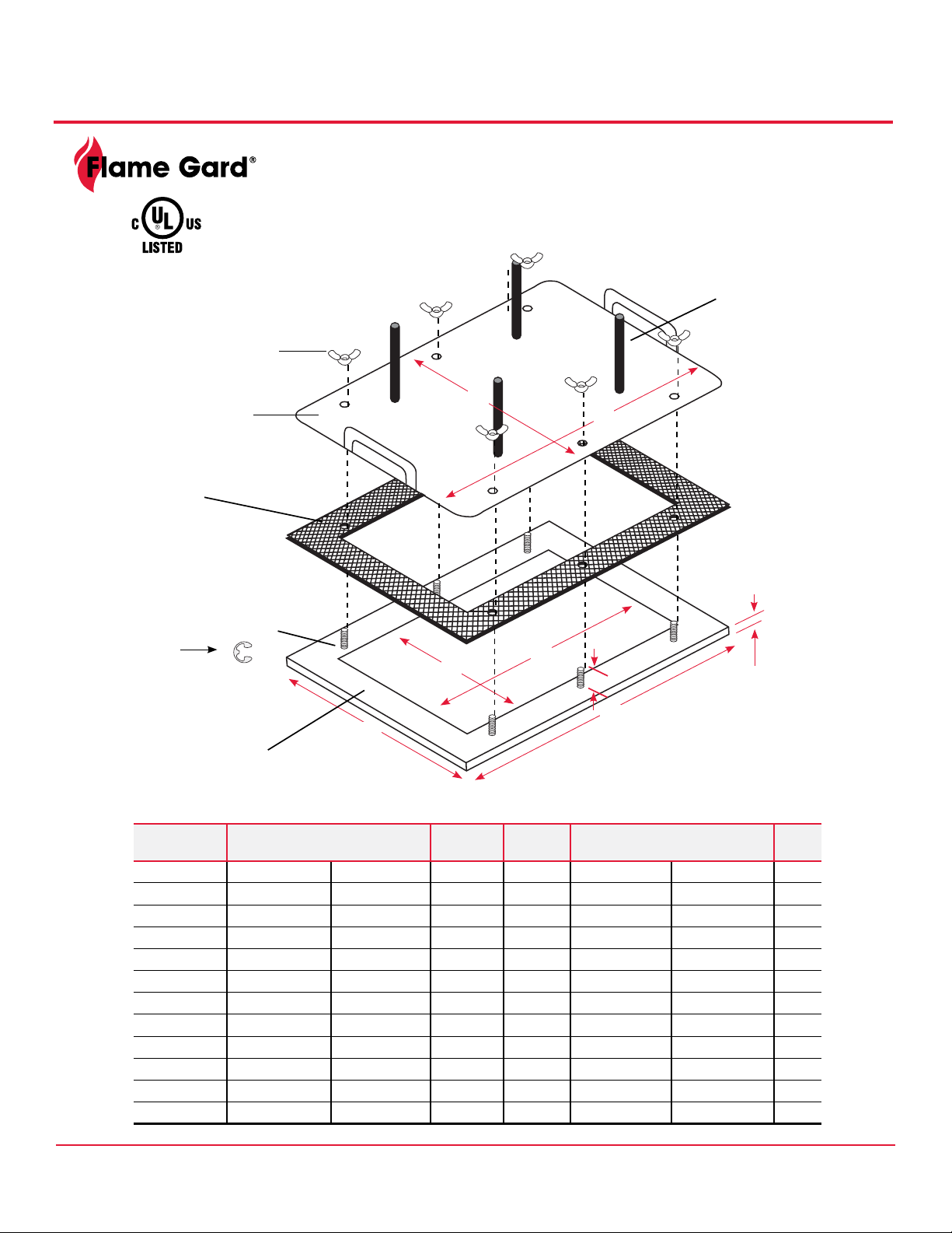
Flat Access Door
Optional 4”(102 mm) studs
for zero clearance duct
wrap-order with sufx (-4)
Wing Nuts
Door
Gasket
NOTE: Gasket is
High Temp bonded
to front panel
E-Clip holds back frame
to duct for each stud
E-Clip
F
E
A
Back
Frame
MODEL NO. PANEL OUTSIDE DIMENSION
A B C D E F
750710 7” (178mm) 10” (254mm) FLAT 1” (25mm) 5.5” (140mm) 8.5” (216mm) 6
750715 7” (178mm) 15” (381mm) FLAT 1” (25mm) 5.5” (140mm) 13.5” (343mm) 6
750723 7” (178mm) 23” (584mm) FLAT 1” (25mm) 5.5” (140mm) 21.5” (546mm) 10
750606 8” (203mm) 8” (203mm) FLAT 1” (25mm) 6” (152mm) 6” (152mm) 4
750707 10” (254mm) 10” (254mm) .5” (13mm) 1” (25mm) 7” (178mm) 7” (178mm) 4
750712 10” (254mm) 15” (381mm) .5” (13mm) 1” (25mm) 7” (178mm) 12” (305mm) 6
750720 10” (254mm) 23” (584mm) .5” (13mm) 1” (25mm) 7” (178mm) 20” (508mm) 10
751212 15” (381mm) 15” (381mm) .5” (13mm) 1” (25mm) 12” (305mm) 12” (305mm) 8
751220 15” (381mm) 23” (584mm) .5” (13mm) 1” (25mm) 12” (305mm) 20” (508mm) 14
751620 19” (483mm) 23” (584mm) .5” (13mm) 1” (25mm) 16” (406mm) 20” (508mm) 16
752020 23” (584mm) 23” (584mm) .5” (13mm) 1” (25mm) 20” (508mm) 20” (508mm) 16
PANEL
HEIGHT
STUD
HEIGHT
B
D
B
HOLE SIZE
Inches (mm)
**Access Panels over
7” x 7” (178mm x 178mm)
have a 1/2” 13mm) turndown to
add rigidity to the panel. Smaller
sizes do not have a turndown.
A
C
MTG
STUDS
1890 Swarthmore Avenue, PO Box 2020, Lakewood, NJ 08701 • Tel. 800-334-3072 • 732-363-4700 • Fax 732-364-8110
Component Hardware Group, Inc.
www.amegardusa.com
 Loading...