

Fitness Quest 1400, Edge 1400 Owner's Manual
1400
Elliptical Trainer
OWNER’S MANUAL
FO R MA XI MU M EF FE CT IV EN ES S AN D
SA FE TY, PL EA SE REA D THIS OWNER’S
MA NUAL BEFORE USING YO UR
ED GE 1400 Elliptical Trainer.

TABLE OF CONTENTS
Important Safety Instructions ...........................................................2
Equipment Warning Labels ..............................................................3
Specifications & Parts .......................................................................3
Introduction .......................................................................................4
Assembly Instructions...................................................................5-12
Edge 1400 Parts List.........................................................................13
Edge 1400 Exploded View .............................................................14
Getting Started ...............................................................................15
Using Your Elliptical Trainer...................................................16
Using The Handlebars.....................................................16-17
Changing Foot Positions......................................................17
Adjusting the Stride Length.................................................17
Operating the Monitor ..............................................................18-20
Care & Storage of Your Elliptical Trainer.......................................21
Exercise Guidelines .........................................................................22
Knowing the Basics....................................................................22
A Complete Exercise Program............................................22-23
Aerobic Exercise: How Much? How Often? ...........................23
When to Exercise .......................................................................23
Measuring Your Heart Rate .................................................23-24
Clothing ......................................................................................24
Tips to Keep You Going.............................................................24
Heart Rate Target Zone Chart..................................................25
Warm Up & Cool Down Stretches ...........................................26-27
Progress Charts................................................................................28
©2006 and ©2007 Fitness Quest Inc. All rights reserved. Made in Taiwan.
Edge
® and Fitness Quest® are registered trademarks of Fitness Quest Inc.
U. S. Utility Patent #6,629,909. Other U.S. and foreign patents pending.
2/5/07

IMPORTANT SAFETY INSTRUCTIONS
Read all instructions before using this equipment
WARNING
YOU AND OTHERS CAN BE SERIOUSLY INJURED OR KILLED
IF WARNINGS ON THE EQUIPMENT AND IN THIS OWNER’S
MANUAL ARE NOT FOLLOWED.
1) Before starting this or any other exercise
program, consult your physician, who can assist
you in determining the target heart rate zone
appropriate for your age and physical condition.
Certain exercise programs or types of equipment may not be appropriate for all people. This
is especially important for people over the age
of 35, pregnant women, or those with pre-existing
health problems or balance impairments.
2) Monitor your heart rate while you exercise
and keep your estimated pulse rate within your
target heart rate zone. Follow the instructions
on pages 23 – 24 in this manual regarding heart
rate monitoring and how to determine your
appropriate target heart rate zone. When used
properly, the heart rate pulse sensors and display
monitor provide a reasonably accurate estimate
of your actual heart rate. This estimate is not
exact and persons with medical conditions
and/or a specific need for accurate heart rate
monitoring should not rely on the estimations
provided.
3) Warm up before any exercise program by doing
5 - 10 minutes of aerobic activity, followed by
stretching.
4) Wear comfortable clothes that allow freedom of
movement and that are not tight or restricting.
5) Wear comfortable shoes made of good support
with non-slip soles.
6) Breathe naturally, never holding your breath
during an exercise.
7) Avoid over training. You should be able to carry
on a conversation while exercising.
8) After an exercise session, cool down with slow
walking and stretching.
9) Start exercise slowly and gradually increase the
amount of resistance.
10) If the user experiences dizziness, nausea, chest
pain, or any other abnormal symptoms, stop
exercise at once and consult a physician
immediately.
11) THIS EQUIPMENT IS NOT FOR USE BY CHILDREN.
To prevent injuries, keep this and all fitness
equipment out of the reach of children.
Follow these simple rules:
– Keep children out of rooms where you
have your exercise equipment.
– Store exercise equipment in a room that
can be locked.
– Know exactly where your children are
when you work out.
– If you have small children at home, don’t
wear headphones while you work out.
– Talk to your kids about the dangers of
exercise equipment.
12) Handicapped or disabled people must have
medical approval before using this equipment
and should be under close supervision when
using any exercise equipment.
13) If you are taking medication which may
affect your heart rate, a physician's advice
is absolutely essential.
14) Use this equipment only for its intended use as
described in this manual. Do not use attachments not recommended by the manufacturer.
15) Only one person at a time should use this
equipment.
16) Do not put hands, feet, or any foreign objects on
or near this equipment when in use by others.
17) Always use this equipment on a solid, level
surface.
18) Never operate the equipment if the equipment
is not functioning properly.
19) Use caution not to pinch fingers or hands in
moving parts when using the equipment.
Risk of electrical shock. This equipment is to be
20)
used only indoors and in a dry location.
KEEP THESE INSTRUCTIONS
2
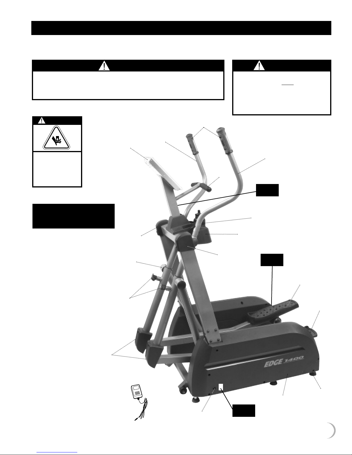
EQUIPMENT WARNING LABELS
Important: See below for placement of the following warning labels on your equipment.
WARNING LABEL 1
WARNING
FAILURE TO READ AND FOLLOW THE SAFETY INSTRUCTIONS STATED IN THE
OWNER’S MANUAL MAY RESULT IN POSSIBLE SERIOUS INJURY OR DEATH.
KEEP CHILDREN AWAY. MAXIMUM USER WEIGHT 300 LBS.
REPLACE THIS LABEL IF DAMAGED, ILLEGIBLE OR REMOVED. CLASS HC.
WARNING LABEL 3
WARNING
CRUSH HAZARD.
KEEP HANDS
CLEAR OF MOVING
PARTS DURING
OPERATION.
SPECIFICATIONS
& PARTS
Edge 1400
Specifications:
Approximate:
Length: 50”
Width: 28”
Height: 63”
Product Weight:
Approx. 186 lbs.
Maximum User Weight:
300 lbs.
EEL1412
onitor
M
•
NB9002-2
Right Frame
Cover
•
NB9015-2A
End Cap
•
NB8002-4
Stride
Adjustment
Knob
•
EL1405R
E
Right
andlebar
H
Assembly
•
EL1405-1
E
Hand Pulse
rips
G
•
Stationary
Handlebar
NB9002-1
Left Frame
EL1407
E
•
•
Cover
WARNING LABEL 2
WARNING
RISK OF ELECTRICAL SHOCK. THIS UNIT
IS TO BE USED ONLY
AND IN A DRY LOCATION.
DO NOT PLUG THE AC ADAPTER INTO
WALL UNTIL ELECTRONICS MONITOR IS
COMPLETELY ASSEMBLED.
EL1405L
E
Left
Handlebar
ssembly
A
•
WARNING
LABEL 1
•
NB9009
Water Bottle
•
NB9010
Water Bottle
Holder
WARNING
LABEL 3
INDOORS
EEL1406R
Right Foot
Platform
•
EEL1406L
Left Foot
Platform
•
•
NB9008
Swing Arm
Cover
NB9013
AC Adapter
•
AC Adapter
Receptacle
WARNING
LABEL 2
•
EEL1401
Base Frame
Assembly
•
NB9001-1
Leveler
3

INTRODUCTION
CONGRATULATIONS ON PURCHASING YOUR
EDGE 1400 ELLIPTICAL TRAINER
ith this product in your home, you have everything you need to start
W
your own workout program to tone and firm the major muscle groups of
your lower body. This is vital for all of us, regardless of age, sex, or fitness
level, and regardless of whether your primary goal is toning, health
maintenance, or more energy for daily activities.
Proper exercise, including a low fat diet, strength training and aerobic
exercise, tones and conditions the muscles we use every day to stand,
walk, lift and turn. It can actually transform our body composition by
reducing body fat and increasing the proportion of lean muscle in
our bodies. Using the Elliptical Trainer will help in reducing body fat
and increasing cardiovascular endurance.
Be sure to read through this Owner’s Manual carefully.
It is the authoritative source of information about your
Elliptical Trainer.
Retain this manual for future reference.
COMMENTS OR QUESTIONS
Dear Customer,
Congratulations on your purchase of your
Elliptical Trainer.
We’re sure that you will be completely satisfied
with the product and we invite your comments
so that we can hear about your success.
Please write or call our Customer Service Specialists
at the address or phone number listed below, or
contact us by email or on our web site, with any
comments or questions you may have.
Edge 1400 Elliptical Trainer
Customer Service Department
1400 Raff Road SW, Canton OH 44750-0001
1-800-321-9236, Monday through Friday
8:30am to 8:00pm, Eastern Standard Time
email: customersupport@fitnessquest.com
www.fitnessquest.com
All details depicted in this Owner’s Manual, and of the
product itself, are subject to change without notice.
ORDERING REPLACEMENT PARTS
When ordering parts, please contact our
Parts Department, toll free at 1-800-497-5831,
Monday through Friday, 8:30am to 8:00pm, EST.
IMPORTANT: You must have your serial number and
this manual ready when calling for parts.
Serial #: _______________________________
Please also provide the following information:
1) Name, Mailing Address and Telephone Number
2) Date of Purchase
3) Where Product was Purchased
(Name of Retail Store, City)
4) Model Number (EEL1400)
5) Part Order Number and Description
4

ASSEMBLY INSTRUCTIONS
Occasionally our products contain components that are
pre-lubricated at the factory. We recommend that you
protect flooring, or anything else the parts may contact,
ith newspaper or cloth.
w
Tools Required (included):
Allen Wrench 5mm & 6mm
Phillips Screwdriver
Socket Wrench 17mm
Open End Wrench 17mm
Lay all the parts out
on the floor as shown
to familiarize yourself
with them.
NB9015-11
Tool Bag
B8015FB
N
Fastener Bag
Steps 1-9)
(
– TOP LAYER –
pright Frame Assembly
U
ight
R
Frame
ube
T
EEL1402-6R
Right
Swing Arm
Assembly
NOTE: All location references, such as front,
rear, left or right, made in these instructions
are from the user being on the equipment
and facing forward.
EEL1402
EL1406L
E
Left Foot
latform
P
eft
L
Frame
ube
T
EL1406R
E
Right Foot
Platform
EEL1402-6L
Left
Swing Arm
Assembly
EEL1403L
Left Rocker
Arm
NB9010
Water Bottle Holder
– MIDDLE LAYER –
EEL1403R
Right Rocker
Arm
NB9009
Water
Bottle
NB9008
Swing Arm
Covers
NB9013
AC
Adapt er
EEL1405L
Left Handlebar
Assembly
EEL1405R
Right
Handlebar
Assembly
EEL1404L
Left
Foot
Tube
– BOTTOM LAYER –
EEL1404R
Right
Foot
Tube
EEL1407
Stationary
Handlebar
Assembly
EEL1412
Monitor
EEL1401
Base Frame
Assembly
5
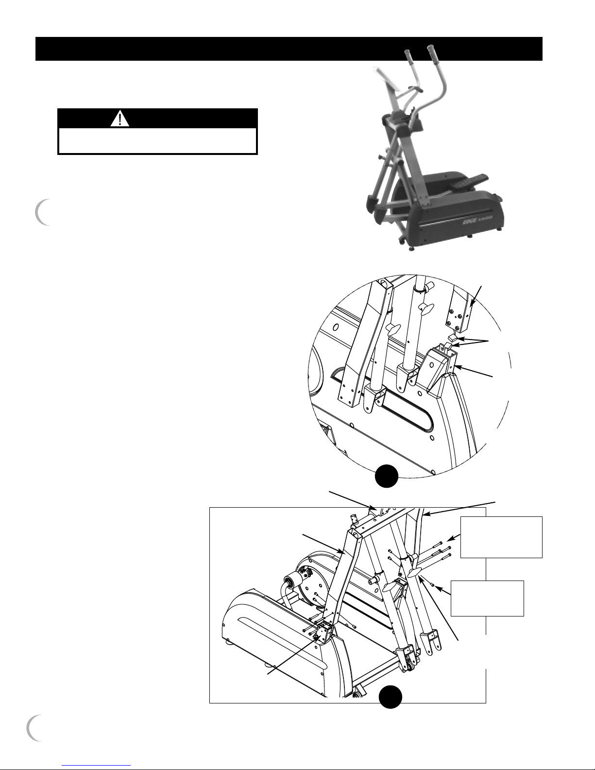
ASSEMBLY INSTRUCTIONS
CAUTION
UPRIGHT FRAME ASSEMBLY IS HEAVY.YOU WILL
NEED TWO PEOPLE TO ASSEMBLE THIS PART.
STEP 1 – Upright Frame Assembly
You will need two people to assemble the Upright
Frame Assembly (shown in 1b) to the Base Frame
Assembly.
Remove Cable Tie from Wire in Base Frame Tube.
a) With the Monitor Bracket to the rear of the
unit and Stride Adjustment Knobs to the front
(shown in 1b), carefully lift the Upright Frame
Assembly above the front of the Base Frame.
Keeps hands clear of moving Swing Arms.
You will need a second person to attach
the Wire coming from the Front Base Frame
Tube to the Wire inside the Left Frame Tube.
Tuck excess Wire into Left Frame Tube.
b) Slide the Upright Frame Assembly onto the
Front of the Base Frame. Insert 4 Bolts into
the side of Right and Left Frame Tubes. Then
insert a small Bolt into the front and 2 small
Bolts into the rear of each Frame Tubes.
Tighten all Bolts with the 5mm Allen
Wrench provided.
monitor
bracket
upright
frame
assembly
left frame tube
attach
wires
front base
frame tube
(left side)
FRONT
1a
left frame
tube
8 - M8 x 55mm
allen bolts
w/lock washer
6
REAR
base frame tube
(right side)
6 - M8 x 16mm
allen bolts
w/lock washer
stride
adjustment
knob
FRONT
1b
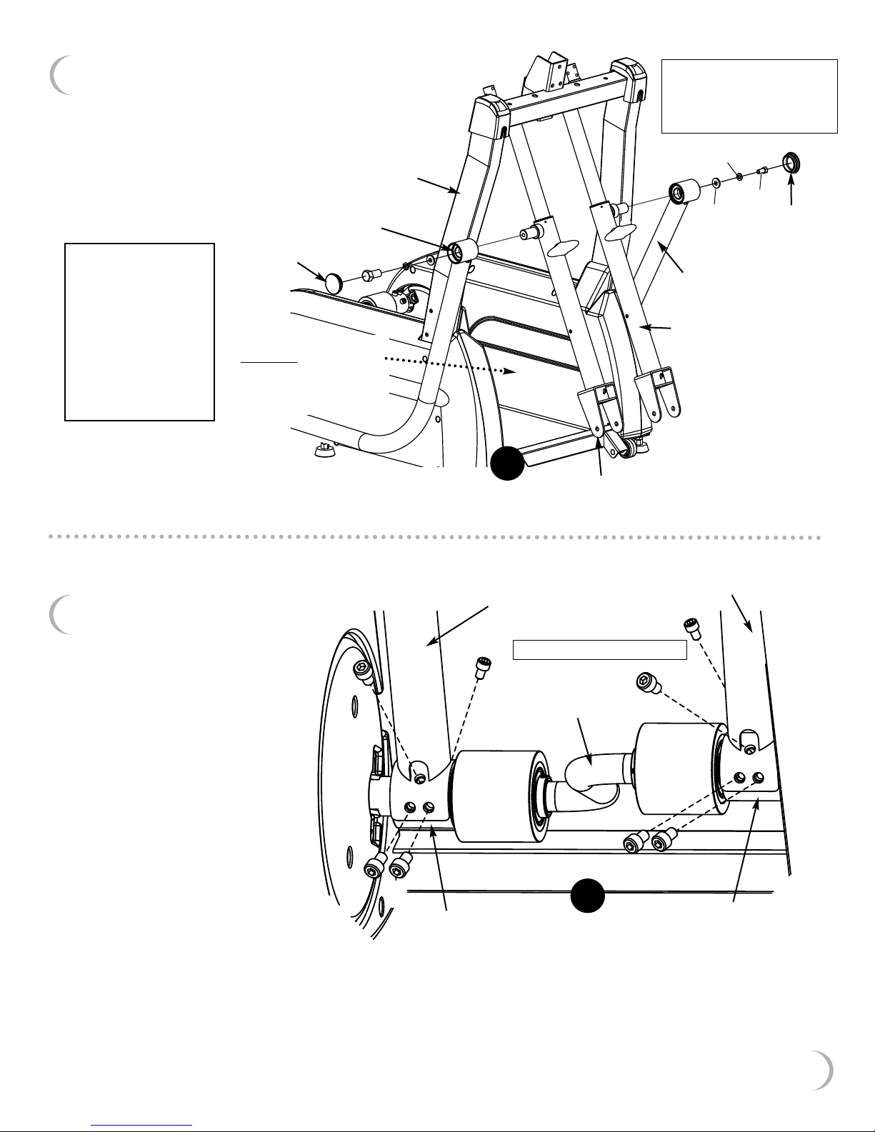
STEP 2 – Top Rocker Arm
Attachment
Slide the Left Rocker Arm onto the
Left Swing Arm.Attach with Hex
olt, Washer and Lock Washer.
B
Tighten with Socket Wrench
provided. Insert Cap. Repeat
on right side.
frame tube
right rocker
arm
2 - M10 x 20mm hex bolts
2 - M10 washers
2 - M10 lock washers
2 - caps
lock washer
bolt
washer
cap
*Important Note:
Rocker Arms should
be placed on the
inside of the unit -
between the Frame
Tube and Swing
Arm. The illustration
shows them on the
outside for your
easy reference.
cap
*Rocker Arm placement
between
and Swing Arm (shown
on outside for easy
reference).
STEP 3 – Bottom Rocker
Arm Attachment
Attach the bottom of Left Rocker
Arm to the small Crank Bearing
w/4 Allen Bolts. Start all 4 Allen
Bolts before tightening. Follow the
sequence A through D as shown.
Frame Tube
A
2
left rocker arm
D
8 - M8 x 12mm allen bolts
left rocker
arm
left swing
arm
right swing arm
right rocker arm
D
A
crank
Note: The hole for Bolt D is not
shown, but is located under the
Rocker Arm.
For ease of assembly, we suggest
you place the Bolt onto the end
of the Wrench. This may help
prevent the Bolt from falling
into the Rocker Arm.
Tighten with the 6mm Allen
Wrench provided.
Repeat on right side.
B
C
small crank
bearing
B
C
3
(rear of unit shown)
small crank
bearing
7
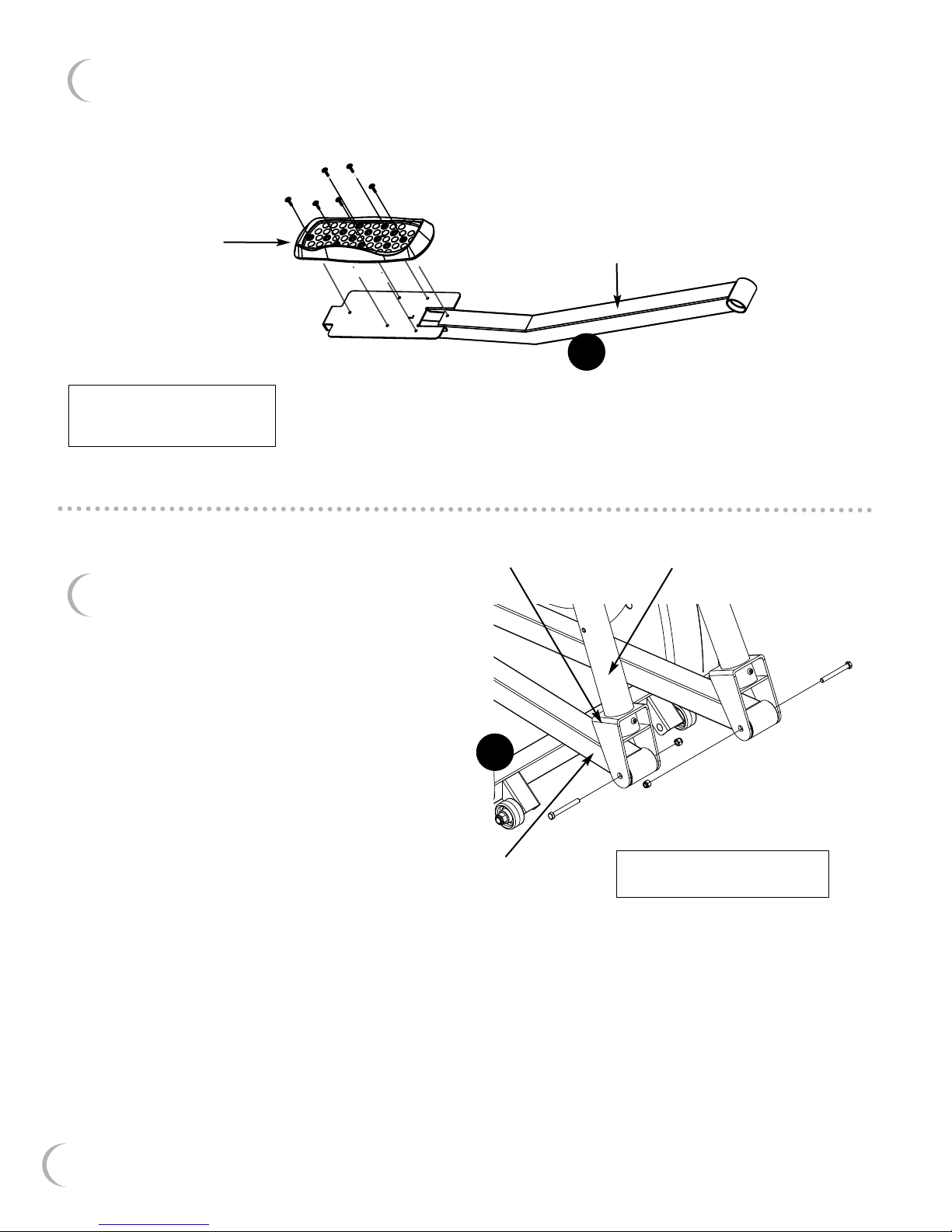
STEP 4 – Foot Platform Assembly
ttach the Left Foot Platform to the Left Foot Tube as shown
A
with 6 Phillips Bolts. Tighten with Phillips Screwdriver provided.
Repeat on Right Foot Tube.
left foot platform
REAR
12 - M5 x 16mm phillips bolts,
6 bolts used on each
Foot Platform Assembly
STEP 5 – Foot Tube/Swing Arm
Assembly
Place the front of the Right Foot Tube
into the Right Swing Arm Bracket at the
bottom of the Right Swing Arm. Attach
with Hex Bolt and Hex Nut. Tighten with
the Socket Wrench and Open End
Wrench tools provided.
Repeat on the Left Swing Arm.
4
right swing arm bracket
5
left foot tube
FRONT
right swing arm
8
right foot tube
FRONT
2 - M10 x 82mm hex bolts
2 - M10 hex nuts
 Loading...