

Fishman RARE EARTH BLEND, RARE EARTH ACTIVE MAGNETIC SOUNDHOLE PICKUP Installation Manual
Permanent Installation Guide
Important!
Permanent installation of the Rare Earth™ requires some degree
of woodworking/electronics soldering skill and should be performed only by a
qualified repair-person. Fishman Transducers will not be held responsible for
damages to the pickup or your instrument that result from improper
installation.
The goal of this procedure is to mount the Rare Earth™ pickup and endpin
jack securely in the guitar. Please follow these guidelines carefully; a pickup
that is not properly mounted may slip out of the soundhole and may damage a
guitar that is shipped or checked as baggage.
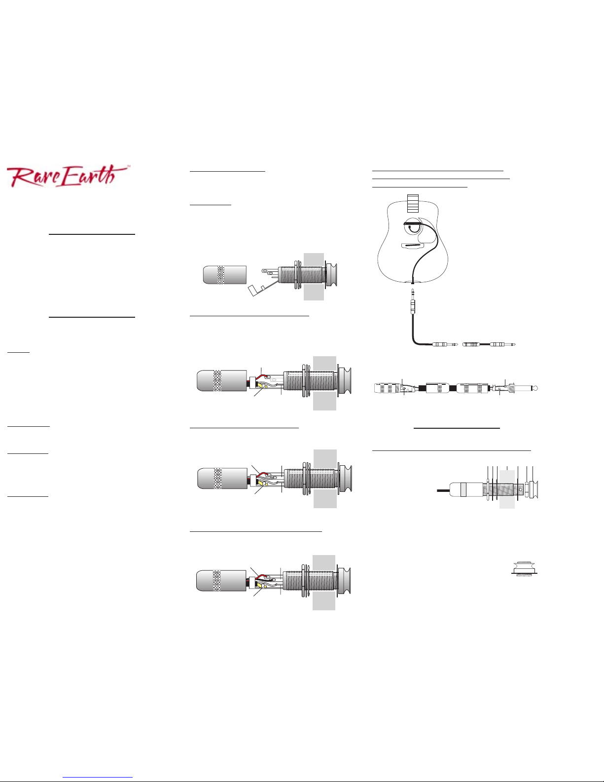
Install the Endpin Jack
Tools
• Soldering iron (30 watt max) • Rosin core solder
• Wire strippers • #1 Phillips screwdriver
• 1/2" open end wrench • 3/32" Allen wrench
• 2.4mm (3/32") slot head screwdriver • #4 washers (#3metric)
• 15/32" (11.9 mm) reamer or: Variable speed drill
Center punch
1/8" (3.2 mm) twist drill
15/32" (11.9 mm) Spade bit drill
X-Acto miniature saw
Procedure
•
Widen the endpin hole to accept the endpin jack.There are two methods to
widen the endpin hole ...
Slow and Safe
If you have the time, this is the preferred method. Remove the endpin and
widen the hole to size with a 15/32" (11.9 mm) reamer (available in the US &
Canada through Stewart Macdonald, 800-848-2273 part #4323).
OR ...
Quick & Clean
The objective here is to quickly drill out the endpin jack hole, with the endpin
or other suitable plug in place. You may remove a loose endpin and refasten
it in the endblock with cyanoacrylate glue before starting the procedure.
Note:
We do not recommend this method for instruments with brittle
ornamental veneers (ex: abalone) around the endblock
1. Apply masking tape around the endblock area to protect the instrument.
2. Locate an X-Acto saw 1/16" (1.6 mm) away from the body and saw off the
endpin, nearly flush to the instrument.
3. Centerpunch a guide hole in the trimmed endpin.
4. Drill a 1/8" (3.2 mm) pilot hole through the endpin and endblock.
5. Line up 15/32" (11.9 mm) Spade bit in the pilot hole and begin drilling.
Maintain a perpendicular plunge in relation to the instrument. Use steady
(but not heavy) pressure, especially as the drill exits inside the guitar.
6. To avoid damage to the instrument, let the drill come to a complete stop
before removing it from the hole.
Wiring Options
Cut the pickup wire (or coil it up and secure with a tie wrap) to a length
suitable to reach between the soundhole and the endpin. Leave extra length to
move the pickup out of the sound hole for battery replacement.
Preliminary
1. Strip 3/8" off the outside jacket of the pickup wire.
2. Tin the red and white wires, as well as the ground wire. With the Blend and
Custom Blend models, clip the blue, yellow and green wires short, as they
are unused. The black wire on the Blend model carries an additional
microphone signal for wiring the pickup/mic in stereo.
3. Gently bend back the ground/strain relief to gain access to the three other
terminals.
Standard Mono Wiring for all Models
1. Solder the white wire (signal) to the shor test terminal on the jack (Tip).
2. Solder the red wire (Neg. battery) to the longest terminal on the jack
(Switch).
3. Solder the pickup shield wire to the Sleeve tab on the jack (Ground).
To add a second pickup in stereo
Solder the signal wire from the second pickup to the Ring terminal (middle
length) of the jack. Solder the shield from the second pickup to the Sleeve
terminal of the jack.
To wire the Rare Earth™ Blend in stereo
To split the pickup and microphone signals to separate destinations: Solder
the black wire (microphone signal) to the middle length terminal (Ring).
To send pickup and microphone signals
to a mono destination with a Rare Earth™
Blend that is wired for stereo
If you wish to go back to a mono output
for a stereo wired Rare Earth Blend,
you may do so without removing and
rewiring the endpin jack. Instead,
make a special adapter with a mono
male plug at one end and a female
stereo jack at the other. Leave the ring
terminal of the female stereo jack
open. Plug the stereo cord from the
Rare Earth Blend into this adapter.
You may now combine microphone and
pickup signals in mono (using the
balance control under the pickup),
without microphone signal degradation
or distortion.
Fasten the Jack in the Endpin Hole
Follow this sequence when installing the endpin jack:
1. Large Hex Nut
2. Large Dress Washer
3. Star Washer
4. Guitar Endblock
5. Small Dress Washer
6. Small Dress Nut
7. Strap Button
The jack should protrude at least 5/16" (7.9 mm) and no more than 11/32"
(8.7 mm) outside the guitar's body for proper fit.
Fit the small dress washer and nut over the end of the jack, then insert a 3/32"
Allen wrench through the small hole on the end of the jack. Tighten the nut
with a 1/2" open-end wrench while holding the jack in place with the Allen
wrench. Thread and hand tighten the strap button.
Note:
With the strap button in place, the end of the jack
should protrude slightly, so that when a plug is inserted,
it will snap securely in place.
A set of adhesive backed clips has been provided to secure the pickup cable
inside of the guitar once the endpin jack has been installed. Remove the
plastic film from the back of each clip to expose the adhesive. Secure the
cable/clips to the kerfed lining of the guitar.
ACTIVE MAGNETIC SOUNDHOLE PICKUP
STEREO T O MONO ADAPTER
1/4" Stereo Jack 1/4" Mono Plug
Tip (short terminal)
Tip
Ring Open (unused)
Shield to Ground
Stereo
Patch Cord
Adapter
To Amp
Shield to
Sleeve
Pickup Signal
(white) to Tip
Negative Battery Wire
(red) to Switch
Shields to
Sleeve
Pickup Signal
(white) to Tip
Negative Battery Wire
(red) to Switch
Second Pickup
to Ring
Shield to
Sleeve
Pickup Signal
(white) to Tip
Negative Battery Wire
(red) to Switch
Microphone Signal
(black) to Ring
1
123 4 567
Permanent
Pickup Installation
1. Loosen the pickup clamps.
2. Position the pickup as close to the fingerboard as possible.The
pickup should be parallel to the fingerboard and centered
between the outside strings.
3. Lightly tighten the clamps with a #1 Phillips screwdriver until
they start to grab. Do not over tighten.
With an inspection mirror, check the clamps inside the guitar.
When properly seated, the moveable jaws will be parallel to the
soundboard. We recommend that you shim the clamps with #4
washers (#3 metric) - see Figure C. This will strengthen the
clamping power of the jaws and prevent damage from
overtightening. Use as many washers as needed to keep the
jaws parallel to the soundboard, while still maintaining a good,
firm grip.
4. With the inspection mirror, check to see if the moveable jaws
touch the support braces that run close to the edge of the
soundhole. If the clamps do not touch these braces, you may
tighten the screws until the clamps are fully seated. Make sure
the pickup is secure; tr y to slide it out of the soundhole. If you
can't move the pickup, you are done.
If after tightening, you can move the pickup with little effort, the
jaws are probably hung up on the interior soundhole braces. If
so, go to step 5.
5. If the tips of the clamps inside the guitar make contact with
the soundhole braces - see Figure D - then the pickup can
not firmly grip the guitar and may slip out of the soundhole
over a period of time.
Try mounting the pickup slightly back toward the center of the
soundhole. Doing so will often clear the clamps from the
soundhole braces. After you move the pickup, re-check with
the inspection mirror. If everything lines up, retighten the
clamps and check the pickup for tightness in the soundhole.
If the clamps are still hung up on the soundhole braces, go to
step 6.
6. Cut back the cork pads on the tips of the moveable jaws - see
Figure E - just enough to keep the pads from touching the
soundhole braces. If the soundhole braces are taller than the
cork pads, shim up the existing pads with a similar material.
A shim kit, consisting of four adhesive-backed cork pads (in
the shape of the clamps), is available through your Fishman
dealer. (Fishman Part # ACC-SHM-KIT).
After you have cut down the pads and replaced the pickup in
the sound hole, retighten the screws and check the pickup for
tightness.
009-040-003 5-99
Clamp is not parallel
NO GOOD
Clamp is parallel
GOOD
INSTALLATION GUIDE
ACTIVE MAGNETIC SOUNDHOLE PICKUP
™
www.fishman.com
NDBOARD
Add washers to
strengthen clamp
Clamp clears brace
GOOD
Cut back cork pad
Clamp touches brace
NO GOOD
A
B
C
D
E
F
 Loading...