

Page 1

USER GUIDE
SBT
Page 2

Read Me First!
Installation of this product is a straightforward procedure, but we recommend
this job only if you are an experienced repair technician.
Plugging In
An impedance matching preamp is recommended, but not required. This will
help realize the full frequency response potential of the pickup and allow for
cable runs longer than 10 feet without signal deterioration. Use a high quality,
low capacitance ¼” shielded instrument cable (models SBT-HP and SBT-E) or the
provided cable (SBT-C). This will ensure minimal tone coloration and hum.
2
Page 3
Installing the Model SBT-C
Parts
• SBT-C Pickup with 1⁄8” Shielded Jack
• (3) Double-sided Adhesive Pads
• Adhesive-backed Jack Holder
• Felt-covered Strain Relief Clip
• 10’ Instrument Cable
3
1.5”
1.5”
Page 4
Preparation
The model SBT-C may be mounted onto a classical guitar, a steel string guitar, a
dulcimer and similar stringed instruments. The installation may be performed
either on the outside of the instrument or inside the soundhole where the
transducer will be out of harm’s way. In instruments with small soundholes
(dulcimers, for example), internal installation may not be practical.
As a general rule, the transducer
should be mounted over a freely
vibrating location and
not over a “dead” structural brace.
The exact location for best results
should be determined
by experimentation.
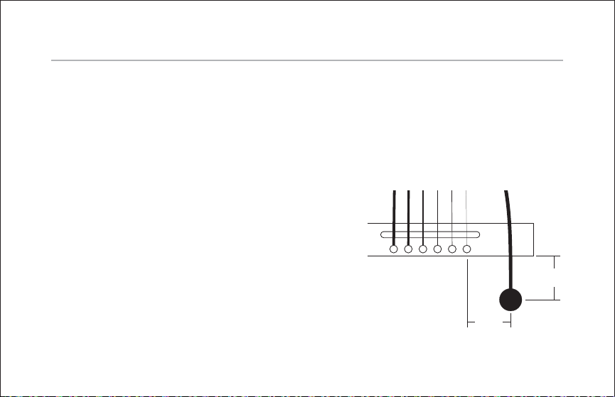
1. Determine the approximate location of the transducer by measuring
about 1.5” (3.8cm)
below the bridge and 1.5” (3.8cm)
JACK
JACK
HOLDER
4
STRAIN
RELIEF
CLIP
Page 5

below the highest pitched string noting the position where these two measurements meet. This will serve as a test location.
2. Apply an adhesive pad to the shiny brass face of the transducer and mount at
the location indicated in step 1. The transducer wire should follow the grain of
the soundboard and point toward the soundhole of the instrument.
Check the location by plugging in the pickup and listening. Should the position
prove unsatisfactory, move the pickup in ¼” increments and re-test until you fi nd
the best position.
Carefully slide a guitar pick or credit card between the transducer and the soundboard to release the foam adhesive. Residual adhesive should then be removed
from the brass surface of the transducer.
Caution: to prevent damage to the transducer when removing the adhesive pad,
do not pull the wire or bend the transducer.
3. Once you have found the “sweet spot” for the pickup, mount it at the same
spot inside the instrument.
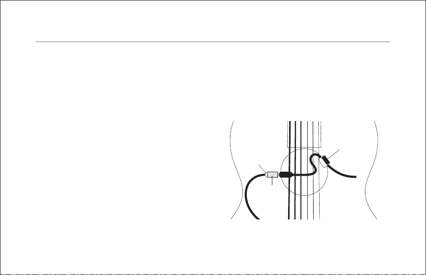
4. Mount the adhesive-backed jack holder to the inside of the instrument
5
Page 6

adjacent to the soundhole.
5. Insert the jack into the jack holder and plug the instrument cable into the jack.
6. Attach the felt-covered strain relief clip to the soundhole.
Note: The felt-covered clip can be bent to accommodate different soundhole
thicknesses.
6
Page 7

Installing the Model SBT-E
Follow the same procedure as the Model SBT-C on page 3 to mount the
pickup element.
Parts:
• SBT-E Pickup
• ¼” Fishman Switchjack stereo endpin jack
• (3) Double-sided Adhesive Pads
7
Page 8

Install the pickup
1. Widen the endpin hole to 15/32” (11.9mm) to accommodate the endpin jack.
For additional information, please refer to the Switchjack Installation Guide
located at fi shman.com.
2. Solder the pickup “hot” wire to the Tip terminal, which is the shortest of
the three tabs. Solder the pickup shield to the Ground tab on the jack. Gently
tighten the strain relief.
Switch
(Long Terminal)
Shield
Ring
(Medium Terminal)
Tip
(Short Terminal)
ratiuG
8
Page 9

Installing the Model SBT-HP
The Model SBT-HP is designed for harp or piano.
Parts
• SBT-HP with 42” Cord and ¼” Jack
• (3) Double-sided Adhesive Pads
• Adhesive-backed Jack Holder
As a general rule, the transducer should be mounted over a freely vibrating
location and not over a “dead” structural brace. The exact location for best
results should be determined by experimentation.
For harp mounting
1. The approximate pickup position will be between
length, starting at the bottom of the soundboard, 1” out from either side of the
center brace. The resulting intersection of the two measurements provides a
good test location for the transducer.
9
1
⁄3 and ½ the soundboard’s
Page 10

2. Apply an adhesive pad to the shiny brass face of the transducer and mount
outside the instrument, at the location indicated in step 1. The transducer wire
should follow the grain of the soundboard and point toward the bottom of the
instrument.
3. Plug the pickup into an amplifi er and experiment with the vertical location of
the transducer. If you detect boominess or feedback, relocate the transducer
higher up on the soundboard. In no case should it be necessary to mount it
higher than ½ the distance. Use increments of about 3 inches.
Caution: Removal for relocation should be performed by gently sliding a thin
plastic credit card between the transducer and the soundboard.
4. Once you have found the “sweet spot” for the pickup, mount it at the same
spot inside the instrument.
5. Plug the instrument into an amplifi er. If boominess or feedback occurs, relocate the transducer as detailed above.
6. Remove the protective fi lm from the bottom of the jack holder and mount the
holder in a convenient location. We recommend a location on the base of the
instrument, if possible. We do not recommend mounting to the soundboard.
10
Page 11

For piano mounting
The SBT-HP should be mounted to the piano soundboard at a location adjacent
to the higher strings. For example, on a grand piano the transducer should be
placed directly on the soundboard within the third-largest ranges of the piano.
For additional instructions, see the above information for harp mounting.
11
Page 12

www.fi shman.com
009-030-001 Rev D 5-10
 Loading...