

Page 1
OWNER’S MANUAL • INSTALLATION GUIDE
Powerchip
PP ii ee zz oo // MM aa gg nn ee tt ii cc OO nn bb oo aa rr dd MM ii xx ii nn gg PP rr ee aa mm pp
PP ii ee zz oo // MM aa gg nn ee tt ii cc OO nn bb oo aa rr dd MM ii xx ii nn gg PP rr ee aa mm pp
Page 2

TM
Powerchip
PP ii ee zz oo// MM aa gg nneett ii cc
PP ii ee zz oo// MM aa gg nneett ii cc
OOnn bb oo aa rr dd MM ii xx ii nn gg PP rr eeaamm pp
OOnn bb oo aa rr dd MM ii xx ii nn gg PP rr eeaamm pp
Thank you for purchasing this Fishman Powerbridge accessory. We are confident that the Powerchip will significantly enhance the performance of your
Powerbridge system. If you have any questions or comments, please contact our Customer Service Line at 978-988-9665.
Warning
Installation of the Powerchip may require structural modification to the guitar. We strongly recommend that any modifications be performed by a competent repair person. Fishman Transducers will be in no way responsible for
damages to the guitar, incurred as a result of improper installation.
Description and Features
The Powerchip is a miniature onboard Piezo/Magnetic pickup mixing preamp, dedicated to the Fishman Powerbridge system. The preamp, mounted
to the underside of a volume pot, allows guitarists to combine or split Piezo
and Magnetic pickups without any additional outboard signal routing electronics.
The Powerchip features an independent Piezo volume control, and internal
“set it and forget it” Phase and Piezo Trim controls. A “smart” electronic
switch in the Powerchip circuit automatically routes Piezo and Magnetic
pickup signals to either stereo or mono signal paths.
2
Page 3
Piezo/Magnetic Outboard Mixing Preamp
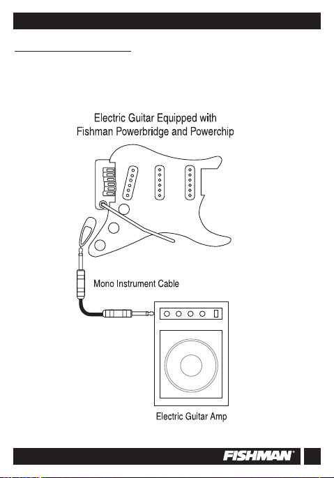
Mono Operation
Plug a standard mono instrument cable into the output of the Powerchip
equipped guitar and combine the Magnetic and Piezo signals into a single
buffered composite, suitable for any available instrument level audio input.
3
Page 4
Powerchip
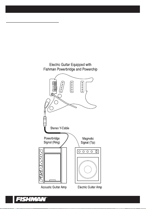
Stereo Operation
Plug a stereo “Y” cable into the output of the Powerchip equipped guitar and
split the Magnetic and Piezo pickup signals to separate destinations. Send
the buffered Piezo signal (Ring) to any instrument level audio input, such as
an acoustic instrument amplifier or PA system. Send the unbuffered,
“immaculate” Magnetic pickup signal (Tip) to a traditional electric guitar
amplifier, with no added coloration or signal treatment between the Magnetic
pickup and the amplifier.
4
Page 5

Piezo/Magnetic Outboard Mixing Preamp
Piezo Trim and Phase
Adjust the small rotary trim pot on the backside of the Powerchip to match
Piezo and Magnetic pickup levels.
Move the Phase jumper on the backside of the Powerchip to eliminate phase
cancellation between the Piezo and Magnetic pickups.
5
Page 6

Powerchip
Prepare the Instrument
TELECASTER
STYLE GUITARS
File or sand down the corners of
the 9-Pin Jack to fit the standard
TelecasterTMmounting hole.
STRATOCASTERTMSTYLE GUITARS
You will need to drill out the back wall of the jack cavity to accommodate the
supplied 9-Pin Jack. Remove the output jack from the jack plate, then
replace the jack plate on the guitar. Use a pencil through the jackplate to
mark the center where your drill will enter the back of the jack cavity. Use a
3/4” (19mm) spade bit to drill out the back of the jack cavity.
TM
6
Page 7

Piezo/Magnetic Outboard Mixing Preamp
Installation and Connections
WARNING:
Powerchip circuit board are quite fragile and can be easily overheated. Use
only a low wattage soldering iron (30 watts max) to make your wire connections. To best utilize the space inside the guitar, solder the wires to the circuit board so that they exit toward the volume pot terminals.
1. Strip 3/32”(2.4 mm) and tin the wire ends of the pickups
2. Solder the Piezo pickup wire to the circuit board
The pads are located on the side of the board opposite the volume pot. The
Piezo hot wire goes to the pad on the right edge of the board, directly under
and to the right of the little white trimmer pot. Solder the Piezo ground wire
(which should be left with the braid intact), to the pad labeled “G” on the
right edge of the board, directly under the Piezo hot wire.
The solder pad terminals and the adjacent components on the
7
Page 8

Powerchip
Installation Continued
3. Solder the Magnetic pickup hot wire to the circuit board
The pad for the hot wire is located on the same side of the board as the volume pot. This pad, labeled “M”, is on the left edge of the board, 3/4”
(19mm) from the bottom of the board. A common system ground is located
on the opposite side of the board, on a second pad marked “G”, adjacent to
the Piezo ground. Since there is room for only one wire on this pad, we suggest that you tie all grounds to the body of the Magnetic volume pot, and
run a jumper wire to the ground pad on the circuit board.
NOTE:
If you install The Powerchip with active magnetic pickups (such as
EMG), the Powerchip and the active pickups will share the same battery.
Connect the positive battery wire from the magnetics to the +9V pad on the
Powerchip. Connect the negative battery wire from the magnetics to terminal #1 on the nine pin jack.
8
Page 9

Piezo/Magnetic Outboard Mixing Preamp
4. Solder the 9-Pin jack to the system
A prewired output cable from the Powerchip is to be soldered to the provided
9-Pin Jack. Prepare the jack by soldering a jumper wire between the sleeve
terminal,located on the business end of the jack, and terminal #2, directly
below.
Solder the jac
a. Solder the shield from the output cable to terminal #2.
b. Solder the red wire from the output cable to terminal #4.
c. Solder the white wire from the output cable the terminal #8.
d. Solder the black battery wire (negative) to terminal #1.
k as follows:
9
Page 10

Powerchip
Optional Accessories
•
Piezo-Magnetic Pickup Selector Switch- A three position switch for
selecting between Piezo and Magnetic pickup combinations.
•
Battery Compartment - A flush mounted, pivoting compartment allows
easy access and quick battery changes.
10
Page 11

Piezo/Magnetic Outboard Mixing Preamp
SSppeecciiffiiccaattiioonnss
Battery Life 200 Hours
Current Draw Less than 2.8 mA
Frequency Range 20-20,000 Hz
Trim Control Range 18 dB
Maximum Output Voltage 15V peak to peak
FENDER, STRATOCASTER, STRAT, TELECASTER and TELE are registered trademarks
of Fender Musical Instruments Corp. with which Fishman Transducers Inc.is not affiliated.
11
Page 12

LIMITED WARRANTY
The FISHMAN POWERCHIP is warranted to function for a period of One (1) Year from
the date of purchase. If the unit fails to function properly within the warranty period, free
repair and the option of replacement or refund in the event that FISHMAN is unable to
make repair are FISHMAN’s only obligations. This warranty does not cover any
consequential damages or damage to the unit due to misuse, accident, or neglect.
FISHMAN retains the right to make such determination on the basis of factory
inspection. Products retur ned to FISHMAN for repair or replacement must be shipped in
accordance with the Return Policy, as follows.This warranty remains valid only if repairs
are performed by FISHMAN. This warranty gives you specific legal rights and you may
also have other rights which may vary from state to state.
RETURN POLICY
To return products to FISHMAN TRANSDUCERS, you must follow these steps...
1. Call FISHMAN TRANSDUCERS at 978-988-9199 for a Return Authorization Number
(“RAN”).
2. Enclose a copy of the original Bill of Sale as evidence of the date of purchase, with
the product in its original packaging and a protective carton or mailer.
3. FISHMAN TRANSDUCERS’ technicians will determine whether the item is covered
by warranty or if it instead has been damaged by improper customer installation or
other causes not related to defects in material or workmanship.
4. Warranty repairs or replacements will be sent automatically free of charge.
5. If FISHMAN TRANSDUCERS determines the item is not covered by warranty, we
will notify you of the repair or replacement cost and wait for your authorization to
proceed.
340-D Fordham Road Wilmington MA 01887 USA
Phone 978-988-9199
www.fishman.com
009-074-001 5-98
•
Fax 978-988-0770
FISHMAN TRANSDUCERS
®
 Loading...