

Page 1
MATRIX INFINITY
PREAMP INSTALLATION GUIDE
www.fishman.com
Read Me First!
Installation of this product is a straightforward
procedure, but we recommend this job only if you
are an experienced repair technician.
Requirements
Saddle Slot:
Minimum saddle slot length: 2.775” (70.48mm)
Maximum E to E string spacing at saddle: 2.5”
(63.5mm)
Wide Format Width: .125” (3.17mm)
Narrow Format Width: .094” (2.39mm)
Preliminary
1. Widen the endpin hole to 15⁄32” (11.9mm) to
accommodate the endpin jack.
2. Drill a 3⁄32” hole (2.4mm) in the saddle slot for the
pickup wire, no less than .100” (2.5mm) from nearest
string.
Standard Installation
5. Open the preamp body by unscrewing the single
screw on the side opposite the Matrix Infi nty logo.
Flip the preamp over so the circuit board remains in
the plastic housing (fi gure 2).
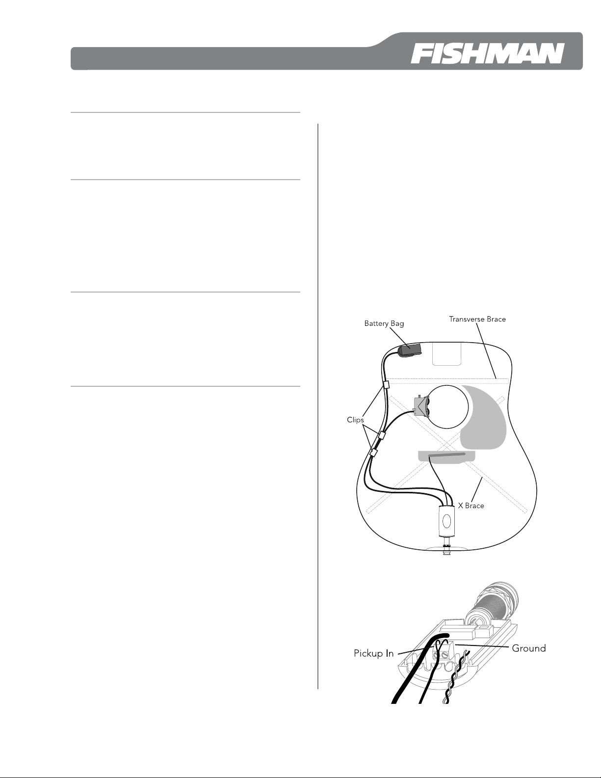
6. Fasten the pickup wires to the terminal block on
the preamp module. The signal wire goes to the terminal marked “IN” and the shield wire goes to the
“GND” terminal. Tighten the screws on the terminal
block to secure the wires.
7. Replace the preamp’s back cover being sure the
wires do not get pinched by any plastic parts. The
housing should easily fasten tightly when the screw
is replaced.
8. Secure the wires inside the instrument with the
supplied adhesive-backed clips (fi gure 1). Clean the
bare wood surface where you will fasten the clips.
Use an alcohol wipe or a cotton swab moistened
with rubbing alcohol.
For nylon string instruments or installation with-
out the control module, refer to the Installation
Options below prior to mounting the Volume &
Tone controls.
1. Test the area where you will mount the Volume
& Tone control module. Locate the module fl ush
with the edge of the soundhole, on the bass side,
between the transverse brace and the bass-side
x-brace (fi gure 1).
2. Remove any lacquer and/or buffi ng compound
from the inside edge of the soundhole. Clean this
surface with an alcohol wipe or a cotton swab moist-
ened with rubbing alcohol. Let dry.
Note: For the strongest bond we recommend that
you now apply a water-based primer/sealer to the
bare wood inside the soundhole. Let the primer/
sealer dry before continuing.
3. Peel back the release fi lm on the bottom of the
preamp module and fasten the preamp to the
underside of the soundhole. Apply even, steady
pressure to the module to set the adhesive. The
adhesive gains maximum hold after 24 hours.
4. Install the pickup per Acoustic Matrix Installation
Instructions.
Figure 1.
Figure 2.
1
Page 2
Battery Bag
Install the battery bag on or near the neck block as
shown in fi gure 1.
1. Clean the area where you will mount the bag with
an alcohol wipe or cotton swab moistened with rub-
bing alcohol. Let dry.
2. Peel off the plastic fi lm from the Velcro patch and
attach the bag at the chosen location.
3. Carefully separate the bag from the Velcro patch.
To set the adhesive, burnish the entire area of the
patch, especially the edges.
4. Install a 9V alkaline or lithium battery. Tuck the
battery into the bag and re-attach to the Velcro
patch. The adhesive under the Velcro patch requires
24 hours to achieve a full bond, so take care to not
stress the adhesive if you remove the battery bag
after the initial installation.
Installation Options
Nylon String Guitar Mount
An optional control module mount is provided in
the package for use with nylon string guitars whose
bracing patterns may interfere with the standard
mount. To install this:
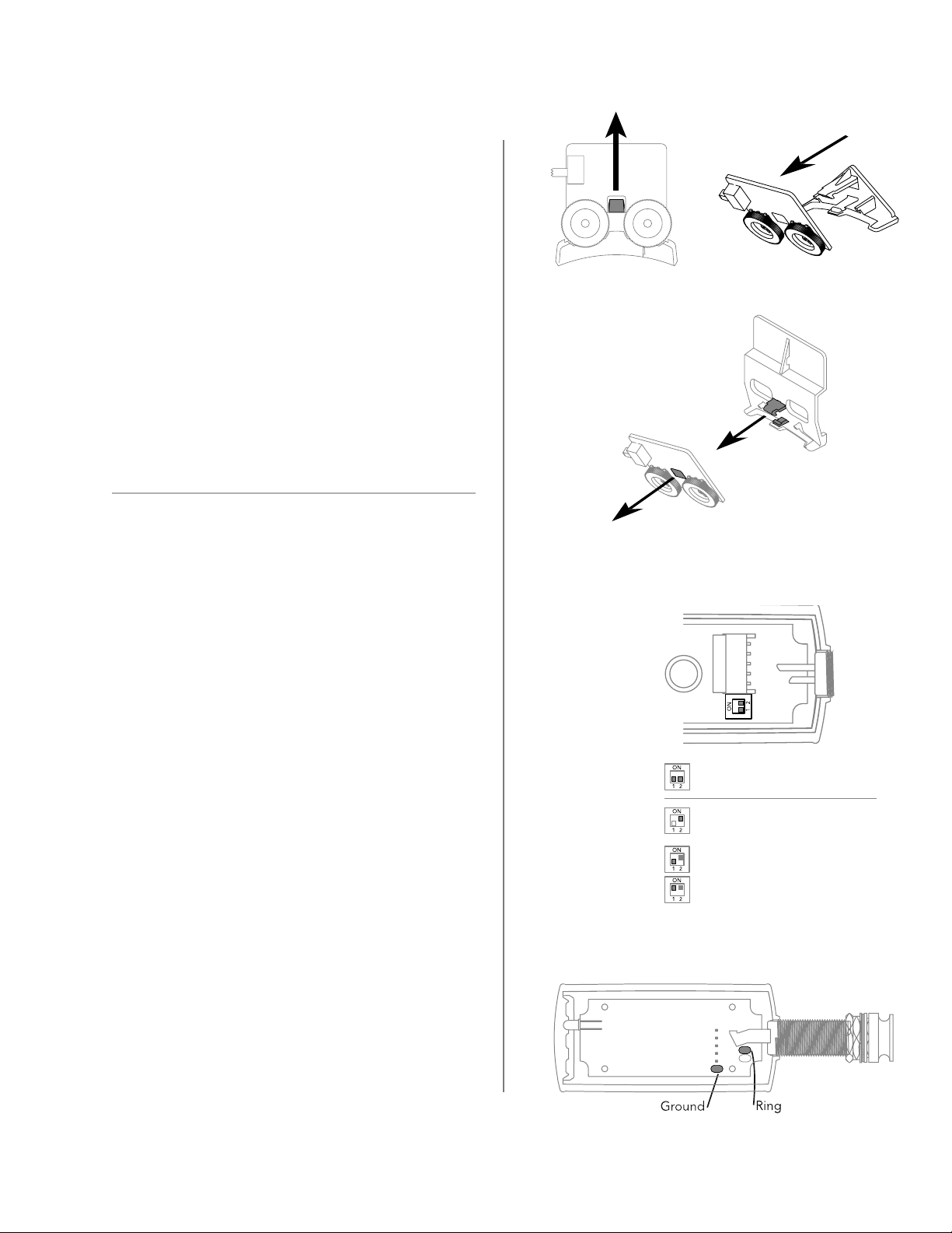
1. Carefully push back the retaining latch and rock
the control module circuit board away from the plas-
tic mount as shown in fi gure 3.
2. Locate the included nylon string guitar mount and
snap it into place as shown in fi gure 4.
Installation Without Controls
Under normal installations, the Volume and Tone
control module is installed in the soundhole. Op-
tionally, the infi nity preamp may be installed without
these controls, however this requires setting the
circuit board-mounted switches appropriately as
shown in fi gure 5.
1. To remove the control module, open the Infi nity
preamp case and gently pull the control module
cable and connector away from its circuit board-
mounted connector.
2. Use switch marked with a “1” to select either a
bass boost (“ON” position) or the fl at setting.
3. Set the switch marked with a “2” to the “ON”
position. This allows the preamp to operate properly
without the control module in place.
Figure 3.
Figure 4.
Figure 5.
Bass Flat
With Volume & Tone
controls installed
If controls are removed:
1. Set switch 2 to ON
2. Choose Flat voicing or
Bass Boost with switch 1.
Second Pickup Source Option
A second source such as a microphone or magnetic
soundhole pickup may be added (fi gure 6). The
output will appear on the ring connection when a
tip-ring-sleeve 1/4” jack is inserted.
For specifi c wiring diagrams, refer to fi shman.com.
2
Figure 6.
514-300-003 Rev A 1-08
 Loading...