

Fisher & Paykel RX256DT4X1 FP, RX256DT7X1 FP, RX256ET2B1 EL, RX256ET2W1 EL Service Manual
321023
Service Manual
Side-by-Side Refrigerator
Fisher & Paykel
Models:
RX256DT4X1 FP
RX256DT7X1 FP
Elba
Models:
RX256ET2B1 EL
RX256ET2W1 EL

321023 - MAY 2009
Fisher & Paykel Appliances Inc
5800 Skylab Rd,
Huntington Beach
California, CA92647
USA
Telephone: 888 936 7872
E-mail: customer.care@fisherpaykel.com
Fisher & Paykel Appliances Canada Inc
2900 – 595 Burrard Street
Vancouver
BC, V7X 1J5
Canada
Telephone: 888 936 7872
E-mail: customer.care@fisherpaykel.com
COPYRIGHT © FISHER & PAYKEL LTD 2008 - ALL RIGHTS RESERVED
2
PRODUCT
Brand: Fisher & Paykel
Models: RX256DT4X1 FP, RX256DT7X1 FP
Brand: Elba by Fisher & Paykel
Models: RX256ET2B1 EL, RX256ET2W1 EL

321023
CONTENTS
1 COMPONENT SPECIFICATIONS ..................................................................................................8
2 PRODUCT DESIGN ........................................................................................................................9
2.1 Refrigeration System................................................................................................................9
2.2 Fully Electronic Defrost System ...............................................................................................9
2.3 Refrigerant Flow .....................................................................................................................11
2.4 Cabinet Air Flow .....................................................................................................................12
2.5 Ice And Water Dispenser Diagram.........................................................................................13
2.6 Water Valve Diagram .............................................................................................................14
2.7 Typical External Sweat Pattern ..............................................................................................15
3 INSTALLATION ............................................................................................................................16
4 WATER FILTER REMOVAL AND INSTALLATION (SELECTED MODELS)..............................19
4.1 Initial Installation.....................................................................................................................19
4.2 Replacing Water Filter............................................................................................................19
5 TEMPERATURE CONTROLS & USER OPTIONS.......................................................................20
5.1 Warm Cabinet Temperatures .................................................................................................20
5.2 Adjusting The Controls ...........................................................................................................20
5.2.1 Touch Temperature Controls (Selected Models - Style Varies by Model).......................20
5.2.1.1 Initial Control Settings...............................................................................................20
5.3 Speed Ice ...............................................................................................................................20
5.4 Reset Filter (Selected Models) ...............................................................................................21
5.5 Vacation Mode .......................................................................................................................21
5.6 Temp Alarm............................................................................................................................21
5.7 Door Alarm ............................................................................................................................. 21
5.8 Max Cool ................................................................................................................................ 21
5.9 User Preferences ...................................................................................................................22
5.9.1 Super Cool (CC) (Selected Models) ................................................................................22
5.9.2 Temperature Display (F_C) ............................................................................................. 22
5.9.3 Alarm (AL) .......................................................................................................................22
5.9.4 Auto Light Level (LL) (Selected Models) .........................................................................22
5.9.5 Sabbath Mode (SAB).......................................................................................................22
6 ICE AND WATER..........................................................................................................................23
6.1 Dispenser Features (Selected Models) ..................................................................................23
6.1.1 Dispensing Light (Selected Models)................................................................................24
6.1.2 Dispenser Pad.................................................................................................................24
6.1.3 Removable Tray ..............................................................................................................24
6.2 Dispenser Control (Selected Models)..................................................................................... 24
6.2.1 Ice Dispenser Operation.................................................................................................. 25
6.2.2 Dispenser Lock (Selected Models).................................................................................. 25
6.2.3 Water Filter Status Indicator Light (Selected Models) .....................................................25
6.2.4 Auto Light (Selected Models) ..........................................................................................25
6.2.5 Light (Selected Models)...................................................................................................25
6.2.6 Sabbath Mode (Selected Models) ...................................................................................26
6.2.7 Front Fill (Selected Models).............................................................................................26
7 COMPONENT TESTING...............................................................................................................27
3

321023
8 ELECTRONIC CONTROL BOARD...............................................................................................33
8.1 Full Electronic Specification Control Board (RX256DT7X1) ...................................................34
8.1.1 Programming Mode .........................................................................................................34
8.1.2 Forced Defrost Mode .......................................................................................................35
8.1.3 Service Test Mode...........................................................................................................35
8.1.4 Service Test Mode - Navigation.......................................................................................36
8.1.4.1 Service Test 001 - Power-Up Test Results...............................................................36
8.1.4.2 Service Test 101 - Defrost Heater. ...........................................................................37
8.1.4.3 Service Test 102 - Compressor/Condenser System. ...............................................38
8.1.4.4 Service Test 112 - Freezer Fan Operation. ..............................................................38
8.1.4.5 Service Test 121 - Damper Operation. .....................................................................39
8.1.4.6 Service Test 141 - Refrigerator Thermistor (See Thermistor Chart in Section 8.1.13).
..................................................................................................................................
39
8.1.4.7 Service Test 142 - Freezer Thermistor Test. (See Thermistor Chart in Section
8.1.13).......................................................................................................................
40
8.1.4.8 Service Test 143 - Ambient Thermistor Test. (See Thermistor Chart in Section
8.1.13).......................................................................................................................
40
8.1.4.9 Service Test 152 - Freezer Door State. ....................................................................41
8.1.4.10 Service Test 161 - Cube Dispense Test. ..................................................................41
8.1.4.11 Service Test 162 - Crush Dispense Test. .................................................................42
8.1.4.12 Service Test 163 - Water Dispense Test. .................................................................42
8.1.4.13 Service Test 164 - Ice Chute Test. ...........................................................................42
8.1.4.14 Service Test 165 - Dispenser Light Test...................................................................43
8.1.4.15 Service Test 171 - Actuator Pad Test.......................................................................43
8.1.4.16 Service Test 172 - Sports Fill Test............................................................................43
8.1.4.17 Service Test 173 - Ambient Light Test......................................................................44
8.1.4.18 Service Test 174 - Dispenser Water Actuator (Bottom Mount units only).................44
8.1.4.19 Service Test 175 - Dispenser Line Test....................................................................44
8.1.4.20 Service Test 181 - Keypad Operation Test...............................................................45
8.1.4.21 Service Test 182 - Indicator Operation Test. ............................................................46
8.1.4.22 Service Test 191 - Valve State Test. ........................................................................46
8.1.4.23 Service Test 241 - Main Control Software. ...............................................................46
8.1.4.24 Service Test 242 - Main Display Software................................................................46
8.1.4.25 Service Test 243 - Main Fountain Software..............................................................46
8.1.4.26 Thermistor Reference Chart .....................................................................................47
8.1.5 Show Room Mode ...........................................................................................................47
8.1.6 Sabbath Mode .................................................................................................................47
8.1.7 Fahrenheit or Celsius Mode.............................................................................................48
8.1.8 Cooling Fan Mode ...........................................................................................................48
8.1.9 Alarm Enable Mode .........................................................................................................48
8.1.10 Light Level Mode .............................................................................................................48
8.1.11 Filter Status Light.............................................................................................................48
8.1.12 Filter Status Light Reset ..................................................................................................49
8.1.13 Thermistor Resistance Chart ...........................................................................................49
8.2 Troubleshooting Flow Chart (RX256DT7X1)..........................................................................50
8.2.1 Compressor Does Not Turn On .......................................................................................50
8.2.2 Evaporator Fan Does Not Turn On..................................................................................51
8.2.3 Damper Does Not Move ..................................................................................................52
8.2.4 Damper Opens and Never Closes...................................................................................53
8.2.5 Flashing Display at Power Up..........................................................................................54
8.2.6 Blank Display ...................................................................................................................55
8.3 Mid Electronic Specification Control Board (RX256DT4X1, RX256ET2B1, RX256ET2W1) ..56
8.3.1 Programming Mode .........................................................................................................56
8.3.2 Forced Defrost Mode .......................................................................................................57
4

321023
8.3.3 Service Test Mode...........................................................................................................58
8.3.4 Service Test Mode – Navigation......................................................................................58
8.3.4.1 Service Test 1 – Defrost Thermostat & Defrost Circuit Test.....................................59
8.3.4.2 Service Test 2 - Compressor/Condenser Fan Test. .................................................59
8.3.4.3 Service Test 3 - Evaporator/Freezer Fan Test. ........................................................59
8.3.4.4 Service Test 4 - Refrigerator Thermistor Test. .........................................................60
8.3.4.5 Service Test 5 - Freezer Thermistor Test.................................................................60
8.3.4.6 Service Test 6 - Open Damper Test.........................................................................61
8.3.4.7 Service Test 7 - Refrigerator Performance Adjustment............................................61
8.3.4.8 Service Test 8 - Freezer Performance Adjustment. .................................................62
8.3.5 Show Room Mode ........................................................................................................... 62
8.4 Troubleshooting Flow Chart (RX256DT4X1, RX256ET2B1, RX256ET2W1)......................... 63
8.4.1 Compressor Does Not Turn On.......................................................................................63
8.4.2 Evaporator Fan Does Not Turn On..................................................................................64
8.4.3 Damper Does Not Move ..................................................................................................65
8.4.4 Damper Opens and Never Closes...................................................................................66
8.4.5 Flashing Display at Power Up .........................................................................................67
8.4.6 Blank Display................................................................................................................... 68
8.5 Defrost Cycle..........................................................................................................................69
9 ELECTRONIC TROUBLESHOOTING..........................................................................................70
9.1 Models RX256DTX1, RX256ET2B1, RX256ET2W1.............................................................. 70
10 GENERAL TROUBLESHOOTING ..........................................................................73
11 DISASSEMBLY PROCEDURES.............................................................................75
11.1 Fresh Food Compartment ......................................................................................................75
11.1.1 Light Switch .....................................................................................................................75
11.1.2 Electronic Control (Full Electronic Specification Model (RX256DT7X1)) ........................75
11.1.3 Ice And Water Dispenser Board...................................................................................... 75
11.1.4 Main Control Board (Full Electronic Specification Model (RX256DT7X1))......................77
11.1.5 Electronic Control (Mid Electronic Specification Models (RX256DT4X1, RX256ET2B1,
RX256ET2W1)) ...............................................................................................................
77
11.1.6 Electronically Controlled Damper ....................................................................................79
11.1.7 Fresh Food Thermistor.................................................................................................... 79
11.1.8 Water Filter Assembly .....................................................................................................79
11.1.9 Water Tank Assembly .....................................................................................................79
11.1.10 Crisper Light Cover and Socket.......................................................................................80
11.2 Freezer Compartment ............................................................................................................80
11.2.1 Freezer Light Socket .......................................................................................................80
11.2.2 Auger Motor Assembly ....................................................................................................80
11.2.3 Auger Motor..................................................................................................................... 80
11.2.4 Auger Motor Capacitor ....................................................................................................80
11.2.5 Evaporator Fan Motor Assembly ..................................................................................... 80
11.2.6 Evaporator Fan Motor and Fan Blade .............................................................................81
11.2.7 Freezer Thermistor.......................................................................................................... 81
11.2.8 Evaporator Removal........................................................................................................81
11.2.9 Defrost Terminator (Thermostat) .....................................................................................81
11.2.10 Defrost Heater .................................................................................................................83
11.2.11 Ice Maker Removal..........................................................................................................83
11.3 Machine Compartment ...........................................................................................................83
11.3.1 Water Valve.....................................................................................................................83
11.3.2 Condenser Fan Motor and Blade ....................................................................................84
11.3.3 Compressor.....................................................................................................................84
11.3.4 Condensate Drain Tube ..................................................................................................84
11.3.5 Condensate Drain Pan ....................................................................................................84
5

321023
11.3.6 Overload/Relay ................................................................................................................84
11.3.7 Condenser Removal ........................................................................................................85
11.4 Bottom of Cabinet...................................................................................................................85
11.4.1 Front Levelling Rollers .....................................................................................................85
11.4.2 Rear Levelling Rollers......................................................................................................85
11.5 Cabinet Doors.........................................................................................................................85
11.5.1 Door Gaskets...................................................................................................................85
11.5.2 Dispenser Façade............................................................................................................85
11.5.3 Dispenser Ice Chute Door ...............................................................................................86
11.5.4 Dispenser Light Socket....................................................................................................86
11.5.5 Dispenser D/C Solenoid ..................................................................................................86
11.5.6 Dispenser Water Tube.....................................................................................................86
12 SEALED SYSTEM DIAGNOSIS ..............................................................................87
12.1 Symptoms of an Overcharge ..................................................................................................87
12.2 Symptoms of Refrigeration Shortage......................................................................................87
12.3 Symptoms of a Restriction......................................................................................................88
12.4 Symptoms of Air in System.....................................................................................................90
12.5 Symptoms of Low or High Ambient Temperature Installation.................................................90
13 SEALED SYSTEM SERVICE PROCEDURES ........................................................92
13.1 Service Equipment..................................................................................................................92
13.2 Drier Replacement..................................................................................................................92
13.3 Refrigerant Precautions..........................................................................................................94
13.4 Line Piercing Valves ...............................................................................................................94
13.5 Open Lines .............................................................................................................................94
13.6 Compressor Operational Test.................................................................................................94
13.7 Dehydrating Sealed Refrigeration System..............................................................................95
13.8 Leak Testing ...........................................................................................................................95
13.8.1 Testing Systems Containing a Refrigerant Charge .........................................................95
13.8.2 Testing Systems Containing No Refrigerant Charge.......................................................95
13.9 Restrictions.............................................................................................................................97
13.9.1 Symptoms........................................................................................................................97
13.9.2 Testing for Restrictions ....................................................................................................97
13.10 Evacuation and Charging .......................................................................................................98
13.10.1 Evacuation .......................................................................................................................98
13.10.2 Charging ........................................................................................................................100
13.10.3 Refrigerant Charge ........................................................................................................100
13.10.4 HFC134a Service Information .......................................................................................100
13.10.5 Health, Safety, and Handling .........................................................................................101
13.11 Replacement Service Compressor .......................................................................................103
13.11.1 Compressor Testing Procedures ...................................................................................103
13.12 Brazing 103
14 WIRING DIAGRAMS..............................................................................................104
14.1 Wiring Schematic (RX256DT7X1) ........................................................................................104
14.2 Wiring Diagram (RX256DT7X1) ...........................................................................................105
14.3 Wiring Schematic (RX256DT4X1, RX256ET2B1, RX256ET2W1)........................................106
14.4 Wiring Diagram (RX256DT4X1, RX256ET2B1, RX256ET2W1) ..........................................107
6
321023
IMPORTANT INFORMATION
Important Notices for Service Technicians and Consumers
Fisher & Paykel Appliances will not be responsible for personal injury or property damage from
improper service procedures. Pride and workmanship go into every product to provide our customers
with quality products. It is possible, however, that during its lifetime a product may require service.
Products should be serviced only by a qualified service technician who is familiar with the safety
procedures required in the repair and who is equipped with the proper tools, parts, testing instruments
and the appropriate service information. IT IS THE TECHNICIAN’S RESPONSIBILITY TO REVIEW
ALL APPROPRIATE SERVICE INFORMATION BEFORE BEGINNING REPAIRS.
WARNING
To avoid risk of electrical shock, personal injury, or death, disconnect electrical power source to unit
before working on/servicing the appliance.
To locate an Authorised Service Centre, please consult the dealer from whom you purchased this
product. For further assistance, please contact:
Fisher & Paykel Customer Care
E-mail
New Zealand
Australia customer.care@fp.com.au
USA/Canada customer.care@fisherpaykel.com
United Kingdom customer.care@fisherpaykel.co.uk
Recognize Safety Symbols, Words, and Labels
customer.care@fp.co.nz 0800 372 273
Telephone
1300 650 590
1 888 936 7872
0845 066 2200
DANGER
DANGER - Immediate hazards that WILL result in severe personal injury or death.
WARNING
WARNING - Hazards or unsafe practices that COULD result in severe personal injury or death.
CAUTION
CAUTION - Hazards or unsafe practices that COULD result in minor personal injury, product or
property damage.
7
321023
1 COMPONENT SPECIFICATIONS
WARNING
To avoid risk of electrical shock that can cause death or severe personal injury, disconnect unit from
power before servicing unless tests require power. Discharge capacitors through a 10,000 ohm
resistor before handling. Wires removed during disassembly must be replaced on correct terminals
to ensure proper grounding and polarization.
Component Specifications all parts 115VAC/60HZ unless noted
Compressor Run Capacitor Volts............................................................................................................... 220 VAC
Compressor BTUH ............................................................................................................. 905 BTUH
Electric Damper Control Maximum closing time (RX256DT7X1) ............................................................ 8 seconds
Thermistor Temperature................................................................................................ Resistance
Condenser Motor Rotation (facing end opposite shaft) .............................................................. Clockwise
Evaporator Fan Motor Rotation (facing end opposite shaft) .............................................................. Clockwise
Overload/Relay Ult. trip amps @ 158°F (70°C) ......................................................................... 2.40 amps ± 15%
Thermostat (Defrost) Volts............................................................................................................ 120/240 VAC
Evaporator Heater
26 cu. ft.
Control Board Volts............................................................................................................... 120 VAC, 60 HZ
Auger Motor Rotation (facing end opposite shaft) Power to blue and white is clockwise. Power to orange
Water Valve Watts.............................................................................................................. Brown side 35W
Capacitance...................................................................................................... 15µfd ± 10%
Watts................................................................................................................. 60 Hz / 153 watts
Current Lock rotor............................................................................................. 19.0 amps ± 15%
Current Full load ............................................................................................... 1.26 amps ± 15%
Resistance Run windings................................................................................. 3.33 ohms ± 15%
Resistance Start windings................................................................................ 4.28 ohms ± 15%
Maximum closing time (RX256DT4X1, RX256ET2B1, RX256ET2W1) .......... 36 seconds
Temperature Rating ......................................................................................... 20°F - 110°F
RPM (RX256DT7X1) ....................................................................................................... 5
RPM (RX 256DT4X1, RX256ET2B1, RX 256ET2W1).............................................. 1
77°F...................................................................................................................................... 10,000 ohms ± 1.8%
36°F...................................................................................................................................... 29,500 ohms ± 1.0%
0°F........................................................................................................................................ 86,300 ohms ± 1.8%
RPM ..................................................................................................................................... 1120 RPM
Watts................................................................................................................. 3.4 watts ± 15% @ 115 VAC
Current.............................................................................................................. 0.085 amps ± 15% @ 115
VAC
RPM ..................................................................................................................................... 2800 RPM
Watts................................................................................................................. 6.0 watts ± 15% @ 115 VAC
Note: Fan blade must be fully seated
on shaft to achieve proper airflow.
Close temperature ............................................................................................ 140° ± 10°
Open temperature (RX256DT7X1) .................................................................. 230° ± 5°
Open temperature (RX256DT4X1, RX256ET2B1, RX256ET2W1)................. 284° ± 9°
Short time trip (seconds) (RX256DT7X1) ...................................................... 17 seconds ± 5
Short time trip (seconds) (RX256DT4X1, RX256ET2B1, RX256ET2W1) ...... 10 seconds ± 5
Short time trip (amps @ 77°F (25°C) .......................................................... 12 amps ± 2 amps
Watts (RX256DT7X1) ............................................................................................ 475 watts
Watts (RX256DT4X1,
Current (RX256DT7X1) ......................................................................................... 10/5 amps
Current (RX256DT4X1,
Resistance across terminals:
Above 42°F ± 5° ............................................................................................... Open
Below 12°F +7° .................................................................................................... Closed
Volts............................................................................................................... 115 VAC
Wattage.......................................................................................................... 450 ± 5% watts @ 115 VAC
Resistance ..................................................................................................... 29 ± 5% ohms
....................................................................................................................... See Control board
troubleshooting section.
RPM ............................................................................................................... 17 ± 3 RPM
Yellow side 20W
RX256ET2B1, RX256ET2W1) ........................................ 495 watts
RX256ET2B1, RX256ET2W1) ..................................... 5.8/2.9 amps
and white is counterclockwise.
8
321023
Light Switch (RX256DT4X1,
RX256ET2B1,
RX256ET2W1)
Light Switch / Interlock Type ............................................................................................................... SPDT NO/NC
Solenoid (Ice Chute) Resistance across leads ................................................................................ 101 ohms ± 10%
Ice Maker Harvest 4 lbs of ice per 24 hours.
Type ............................................................................................................... SPST NC
Volts ............................................................................................................... 125/250 VAC
Current ........................................................................................................... 8/4 amps
Volts ............................................................................................................... 125/250 VAC
Current ........................................................................................................... 8/4 amps
No-Load Performance, Controls in Normal Position
Percent Run Time
Kw/24 hr ±0.4
Ambient °F 70° 90° 110° 70° 90° 110° 70° 90° 110° 70° 90° 110° 70° 90° 110°
26cuft 1.2 1.85 2.6 35 55 75 24 24 19 37 39 42 0 0 -2
Evaporator Outlet
Ambient °F 70° 90° 70° 90° 70° 90° 70° 90° 70° 90° 70° 90°
26cuft -15 -15 -16 -16 72 98 132 138 6"(Vac.) 0 87 137
±3°F
Evaporator Inlet
±10%
Temperature Relationship Test Chart
±3°F
Cycles/24 hr
±25%
Suction Line
±7°F
Provision Center
Compartment
Average Food
Temperature ±3°F
Average Total
Wattage ±10%
Freezer Compartment
Average Food
Temperature ±3°F
Suction Pressure
±2 PSIG
Head Pressure
± 5 PSIG
2 PRODUCT DESIGN
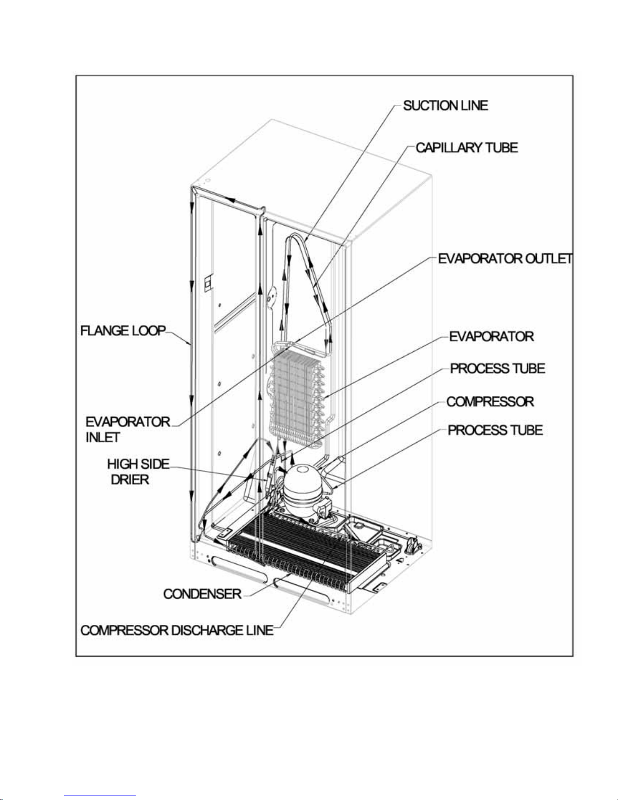
2.1 Refrigeration System
The compressor forces high temperature vapor into the fan cooled tube and wire condenser, where
vapor is cooled and condensed into high pressure liquid by circulation of air across the condenser
coil (refer to Section
High-pressure liquid passes into a post-condenser loop, which helps to prevent condensation
around the freezer compartment opening, and through the molecular sieve drier and into the
capillary tube. The small inside diameter of the capillary offers resistance, decreasing pressure and
temperature of the liquid discharged into the evaporator. The capillary diameter and length is
carefully sized for each system.
The capillary enters the evaporator at the top front. Combined liquid and saturated gas flows
through the front to the bottom of the coil and into the suction line. The aluminium tube evaporator
coil is located in the freezer compartment where the circulating evaporator fan moves air through the
coil and into the fresh food compartment.
The large surface of the evaporator allows heat to be absorbed from both the fresh food and freezer
compartments, by airflow over the evaporator coil causing some of the liquid to evaporate. The
temperature of the evaporator tubing near the end of the running cycle may vary from –13
O
25
F (-25OC to –31OC).
Saturated gas is drawn off through the suction line, where superheated gas enters the compressor.
To raise the temperature of the gas, the suction line is placed in heat exchange with the capillary.
2.3).
O
F to –
2.2 Fully Electronic Defrost System
The Control Board adapts the compressor run time between defrosts to achieve optimum defrost
intervals by monitoring the length of time the defrost heater is on.
9

321023
After initial power up, the defrost interval is 4 hours compressor run time. Defrost occurs
immediately after the 4 hours.
Note: Once the unit is ready to defrost, there is a 4 minute wait time prior to the beginning of the
defrost
cycle.
10
2.3 Refrigerant Flow
321023
11

321023
2.4 Cabinet Air Flow
12
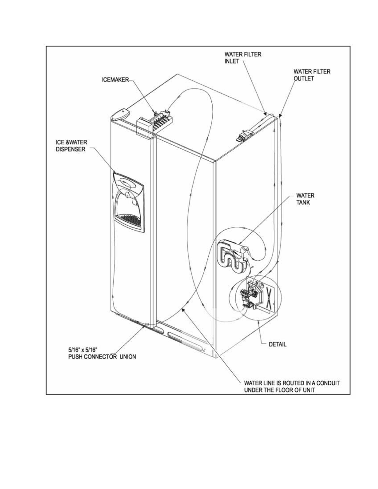
2.5 Ice And Water Dispenser Diagram
321023
13

321023
2.6 Water Valve Diagram
14
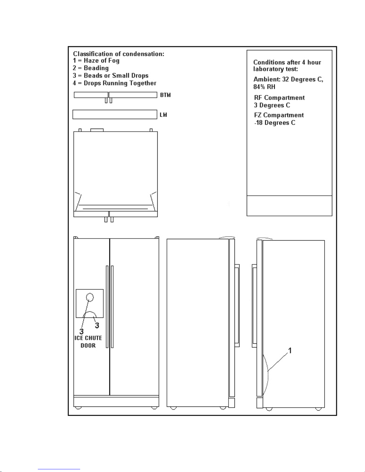
2.7 Typical External Sweat Pattern
321023
15
321023
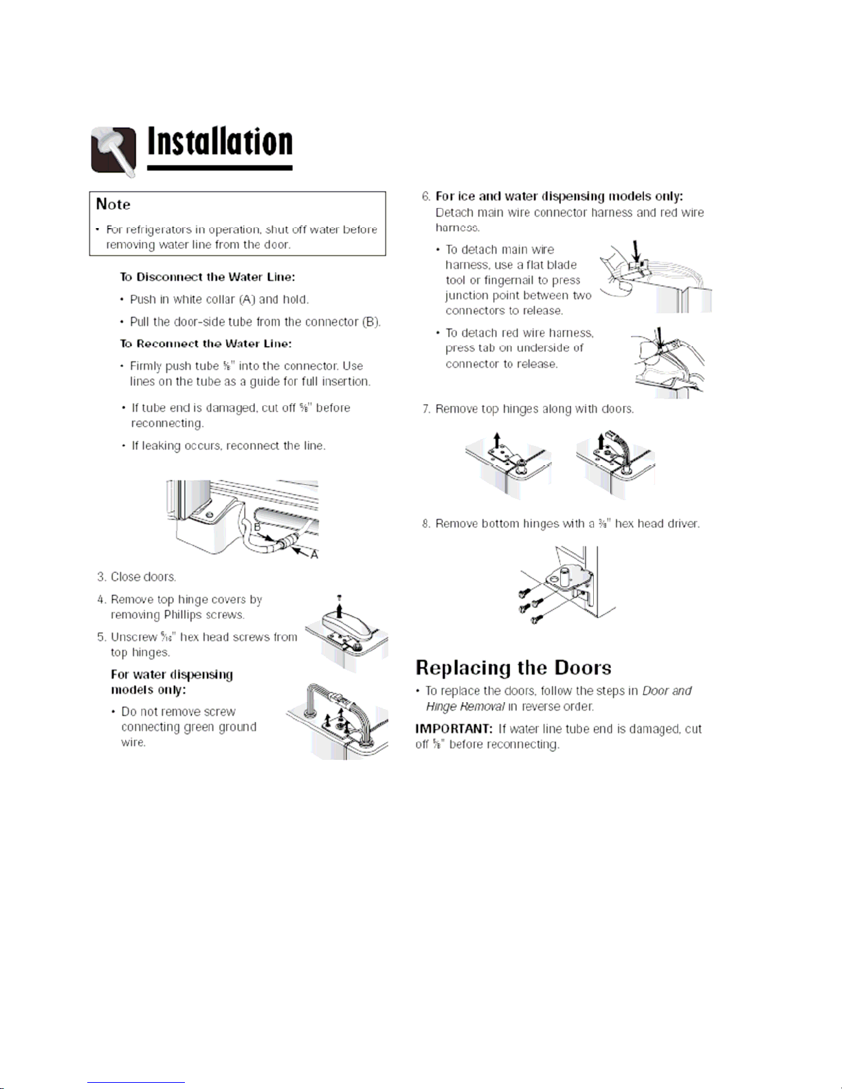
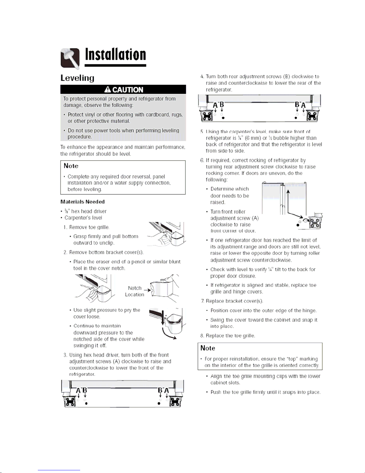
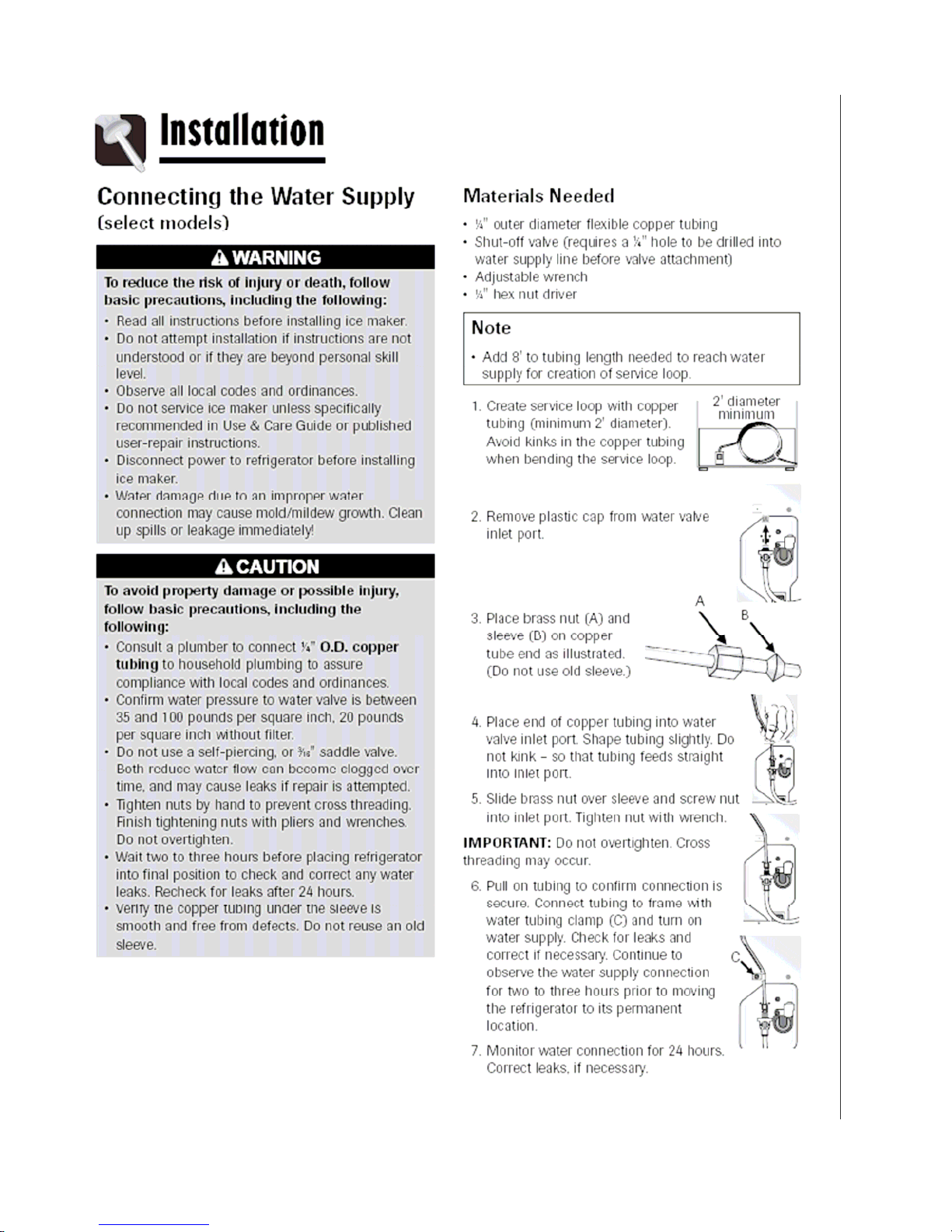
3 INSTALLATION
16
321023
17
321023
18
321023
4 WATER FILTER REMOVAL AND INSTALLATION
(SELECTED MODELS)
WARNING
To avoid serious illness or death, do not use the refrigerated water where the water is unsafe or of
unknown quality without adequate disinfection before or after filtration.
CAUTION
After installing a new water filter, always dispense water for two minutes before removing the filter
for any reason. Air trapped in the system may cause water and the cartridge to eject. Use caution
when removing.
The bypass cap does not filter water. Be sure to have a replacement cartridge available when a
filter change is required.
If the water filtration system has been allowed to freeze, replace the filter cartridge.
If the system has not been used for several months, or water has an unpleasant taste or odor,
flush the system by dispensing water for two or three minutes. If the unpleasant taste or odor
persists, change the filter cartridge.
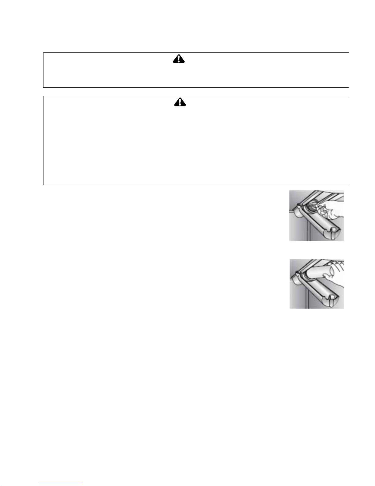
4.1 Initial Installation
The water filter is located in the upper right-hand corner of the fresh food
compartment.
Remove the blue bypass cap and retain for future use.
Remove the sealing label from the end of the filter and insert the filter into
the filter head.
Rotate gently clockwise until the filter stops. Snap the filter cover closed.
Reduce water spurts by flushing air from the system. Run water continuously for two minutes
through the dispenser until the water runs steadily. During initial use, allow
about a one to two minute delay in water dispersal to allow the internal
water tank to fill.
Additional flushing may be required in some households where water is of
poor quality.
4.2 Replacing Water Filter
IMPORTANT: Air trapped in the system may cause water and the
cartridge to eject. Use caution when removing.
Turn the filter counterclockwise until it releases from the filter head.
Drain the water from the filter into a sink and dispose of the filter in normal household trash.
Wipe excess water from the filter cover and install the new filter as described in Initial Installation
above.
The filter should be changed at least every 12 months.
IMPORTANT: The condition of the water and the amount used determines the life span of the water
filter cartridge. If the water use is high, or if the water is of poor quality, replacement may need to take
place more often.
The dispenser feature may be used without a water filter cartridge. If this option is chosen, replace the
filter with the blue bypass cap.
19

321023
5 TEMPERATURE CONTROLS & USER OPTIONS
5.1 Warm Cabinet Temperatures
At times, the front of the refrigerator cabinet may be warm to touch. This is a normal occurrence that
helps prevent moisture from condensing on the cabinet. This condition will be more noticeable when
the refrigerator is first started, during hot weather and after excessive or lengthy door openings.
5.2 Adjusting The Controls
24 hours after adding food, the customer may decide that one or both compartments should be
colder or warmer, so they can adjust the control(s) as indicated in the temperature control guide
table below.
Except when starting the refrigerator, do not change either control more than one number at a time.
Allow 24 hours for temperatures to stabilize.
Changing either control will have some effect on the temperature of the other compartment.
5.2.1 Touch Temperature Controls (Selected Models - Style Varies by Model)
The controls are located at the top front of the fresh food compartment compartment.
5.2.1.1 Initial Control Settings
Pressing the TEMPERATURE UP or TEMPERATURE DOWN keypads, adjust the controls to the
desired setting.
Set the freezer control to 4.
Set the fresh food compartment control to 4.
Let the refrigerator run for at least 8 to 12 hours before adding food.
Fresh food compartment too
warm.
Set the fresh food compartment control to the next higher
number by pressing the FRESH FOOD
COMPARTMENT TEMPERATURE UP keypad.
Fresh food compartment too
cold.
Freezer too warm. Set the FREEZER control to the next higher number by
Freezer too cold. Set the freezer control to the next lower number by
Turn refrigerator OFF. Press the freezer or fresh food compartment
Set the fresh food compartment control to the next lower
number by pressing the FRESH FOOD
COMPARTMENT TEMPERATURE DOWN keypad.
pressing the FREEZER TEMPERATURE UP keypad.
pressing the FREEZER TEMPERATURE DOWN
keypad.
TEMPERATURE DOWN keypad until a dash “-“ appears
in the display.
5.3 Speed Ice
When activated, Speed Ice reduces the freezer temperature to the optimum setting for 24 hours in
order to produce more ice.
NOTE: When the Speed Ice feature is in operation, the FREEZER TEMPERATURE UP and
FREEZER TEMPERATURE DOWN keypads will not operate.
20

321023
5.4 Reset Filter (Selected Models)
When a water filter has been installed in the refrigerator, the yellow ORDER light will illuminate when
90 percent of the volume of water for which the filter is rated has passed through the filter OR 11
months have elepsed since the filter has been installed.
The red REPLACE light will illuminate when the rated volume of water has passed through the filter
OR 12 months have elepsed since the filter was installed. A new filter should be installed immediately
when the REPLACE light is illuminated.
After replacing the filter, press the RESET FILTER keypad for three seconds. The ORDER and
REPLACE lights will go out on the display.
5.5 Vacation Mode
The Vacation Mode feature causes the freezer to defrost less frequently, conserving energy. The
VACATION MODE indicator light will illuminate when the feature is activated. To deactivate, press
the VACATION MODE keypad again OR open either door. The indicator light will go out.
NOTE: Door openings will not deactivate the Vacation Mode for approximately one hour after
activation.
5.6 Temp Alarm
The Temp Alarm will alert the customer if the freezer or fresh food compartment temperatures exceed
normal operating temperatures due to a power outage or other event. When activated, the TEMP
ALARM light will illuminate.
If the freezer or fresh food temperatures have exceeded these limits, the display will alternately show
the current compartment temperatures and the highest compartment temperature reached when the
power was out. An audible alarm will sound repeatedly.
Press the TEMP ALARM keypad once to stop the audible alarm. The TEMP ALARM light will
continue to flash and the temperature display will alternate until the temperatures have stabilized.
To turn off Temp Alarm, press and hold the TEMP ALARM keypad for three seconds. The indicator
light will go out.
5.7 Door Alarm
The Door Alarm will alert the customer when one of the doors has been left open for five minutes
continuously. When this happens, an audible alarm will sound every few seconds until the door is
closed OR the DOOR ALARM keypad is pressed to deactivate the feature.
5.8 Max Cool
When activated, Max Cool causes the fresh food and freezer compartmentment temperatures to drop
to the minimum settings on the control. This cools down the fresh food and freezer compartments
after extended door openings or when loading the compartments with warm food.
NOTE: When the Max Cool feature is activated, the temperature setting kaypads will not operate.
To activate, press the MAX COOL keypad. Max Cool will deactivate automatically after 12 hours, OR
press the MAX COOL keypad to deactivate the feature.
21

321023
5.9 User Preferences
Access the User Preferences menu to:
Activate or deactivate Super Cool (selected models).
Change the temperature display from
Enable or diable audible alarms.
Adjust the light level at which the Dispenser Auto Light will illuminate (when this feature is activated
on the ice and water dispenser) (selected models).
Activate the Sabbath Mode.
To access the User Preferences menu, press and hold the DOOR ALARM keypad for three seconds.
When in the User Preferences mode, a short title for the feature will appear in the freezer temperature
display. And the feature status will appear in the fresh food display.
Use the FREEZER TEMPERATURE UP and FREEZER TEMPERATURE DOWN keypads to scroll
through the features.
When the desired feature is displayed, use the FRESH FOOD COMPARTMENT TEMPERATURE
UP and FRESH FOOD COMPARTMENT TEMPERATURE DOWN keypads to change the status.
When changes are complete, press the DOOR ALARM keypad for three seconds OR close the
fresh food compartment door and any change will be saved.
5.9.1 Super Cool (CC) (Selected Models)
When Super Cool is ON, an air-mixing fan in the fresh food compartment is activated to improve air
flow and temperature control. To save energy, this feature may be deactivated by choosing OFF.
O
F to OC.
5.9.2 Temperature Display (F_C)
Change the temperature display to show in degrees Fahrenheit or degrees Celsius.
5.9.3 Alarm (AL)
When the Alarm mode is OFF, all audible alarms will be disabled until the feature is turned on.
5.9.4 Auto Light Level (LL) (Selected Models)
This setting adjusts the light level at which the dispenser light will illuminate when the sensor detects
that the light levels in the room are low. Setting 1 is the darkest light level setting, setting 9 is the
lightest light level setting.
NOTE: The Auto Light mode must be activated on the ice and water dispenser control to take
advantage of this option.
5.9.5 Sabbath Mode (SAB)
When the Sabbath Mode is ON, all control lights and the night light will be disabled until the feature is
turned OFF. This feature does not disable the interior lights. Press any keypad to restore the control
lights.
22

6 ICE AND WATER
6.1 Dispenser Features (Selected Models)
Full Electronic Specification Dispenser Panel
Mid Electronic Specification Dispenser Panel
321023
Elba Dispenser Panel
23
321023
6.1.1 Dispensing Light (Selected Models)
A light activates within the dispenser area at full power when dispensing ice or water with the main
dispenser pad.
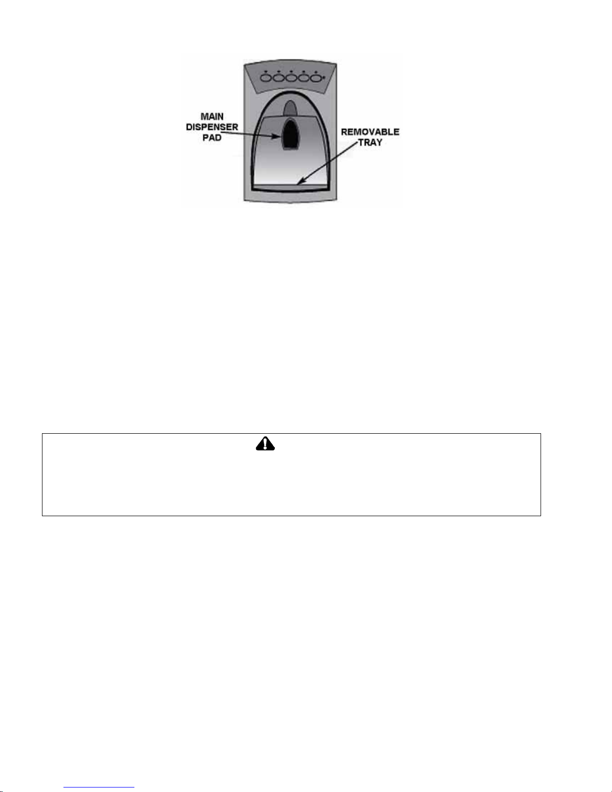
6.1.2 Dispenser Pad
The dispenser pad is located on the back wall of the dispensing area. When the dispenser pad is
pressed, the selection chosen on the dispenser control panel will dispense.
6.1.3 Removable Tray
The removable tray at the bottom of the dispenser area is designed to collect small spills and may be
easily removed for emptying and cleaning purposes.
IMPORTANT: The removable tray does not drain. Do not allow the tray to overflow. If it does,
remove the tray and wipe up the overflow.
6.2 Dispenser Control (Selected Models)
Control features may vary by model.
Water Dispenser Operation:
CAUTION
To aviod personal injury or property damage, observe the following:
Do not put fingers, hands or any foreign object into the dispenser opening.
Do not use sharp objects to break ice.
Do not dispense ice directly into thin glass, fine china or delicate crystal.
NOTE: During initial use of the water dispenser, there will be a one to two minute delay while the
water tank fills before water dispenses. Discard the first 10 to 14 glasses of water after initially
connecting the refrigerator to the household water supply and after extended periods of non-use.
To Use Dispenser Pad:
Select water mode by pressing the WATER keypad on the dispenser control panel. A green light
above the keypad indicates the mode selected.
Press a sturdy, wide-mouthed container against the dispenser pad.
Release pressure on the dispenser pad to stop the water dispensing. A small amount of water may
continue to dispense and collect in the dispenser tray. Large spills should be wiped away.
24

321023
6.2.1 Ice Dispenser Operation
To Dispense Ice:
Select Crush or Cube mode by pressing the appropriate keypad on the dispenser control panel. A
green light above the keypad indicates the mode selected.
Press a container against the dispenser pad. When dispensing crushed ice, hold the container as
close as possible to the chute to reduce spraying.
NOTE:
The mode cannot be changed while the ice dispenser is in operation.
On selected models, if the dispenser is active for more than five minutes, an automatic lock-out
sensor will shut down power to the dispenser area. Refer to Dispenser Lock below for unlocking
information.
6.2.2 Dispenser Lock (Selected Models)
The Dispenser Lock prevents ice or water from being dispensed.
To Lock Dispenser:
Press and hold the LOCK keypad for three seconds. The green indicator light above the keypad
will illuminate when the dispenser is locked.
To Unlock Dispenser:
Press and hold the LOCK keypad for three seconds. The green indicator light above the keypad
will go out.
6.2.3 Water Filter Status Indicator Light (Selected Models)
The Water Status Indicator Light serves as a reminder to replace the water filter. A green light
indicates that the filter is in good condition. A red light indicates that the filter should be changed.
Once the light turns red, it will remain red until the function is reset.
To Reset Indicator:
Press and hold the LOCK and WATER keypads simultaneously for four seconds. The green filter
status indicator light will flash three times when the function has successfully reset.
6.2.4 Auto Light (Selected Models)
The Auto Light function activates the dispenser light at half power when the light sensor detects that
the light levels in the room are low.
To Activate Auto Light:
Press the AUTO LIGHT keypad. A green indicator light above the keypad illuminates when the
sensor is active.
To Deactivate Auto Light:
Press the AUTO LIGHT keypad. The green indicator light will go out.
NOTE: The dispenser light will operate whether Auto Light is ON or OFF.
6.2.5 Light (Selected Models)
To Activate Light:
Press the LIGHT keypad to turn the dispenser light on continuously. The green indicator light
above the keypad will illuminate.
To Deactivate Light:
Press the LIGHT keypad to turn the dispenser light off.
25

321023
6.2.6 Sabbath Mode (Selected Models)
When activated, the Sabbath Mode deactivates the control lights while leaving the controls
operational.
To Activate Sabbath Mode:
Press and hold both the LOCK and AUTO LIGHT keypads simultaneously for three to four
seconds, or until the control lights turn off.
To Deactivate Sabbath Mode:
Press and hold both the LOCK and AUTO LIGHT keypads simultaneously for three to four
seconds, or until the control lights turn on.
NOTE:
The dispenser light will not activate during dispensing while in this mode.
If the power fails, the control remains in Sabbath Mode when the power is restored.
6.2.7 Front Fill (Selected Models)
The Front Fill keypad works independently of the dispenser controls, providing an up-front alternative
to the dispenser pad for dispensing water. This feature is convenient for filling large items that will not
fit into the dispenser area (i.e. sports bottles, pitchers, large pans, coffee pots).
This feature allows the added convenience of dispensing ice and water simultaneously. To do so,
choose the preferred ice mode. Press the container against the dispenser pad to dispense the ice
while pressing the Front Fill keypad to dispense the water.
26
7 COMPONENT TESTING
Component Description Test Procedures
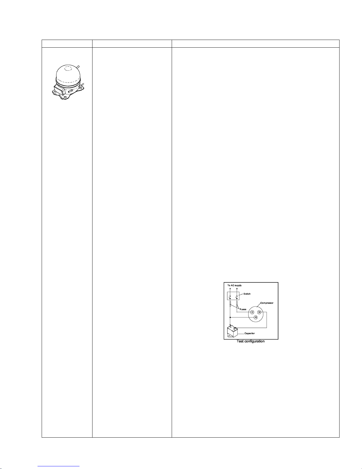
Compressor
When compressor electrical
circuit is energized, the start
winding current causes relay
to heat. After an amount of
starting time, the start winding
circuit turns off. The relay will
switch off the start winding
circuit even though
compressor has not started
(for example, when attempting
to restart after momentary
power interruption).
With “open” relay, compressor
will not start because there is
little or no current to start
windings. Overload protection
will open due to high locked
rotor run winding current.
With “shorted” relay or
capacitor, compressor will
start and overload protector
will quickly open due to high
current of combined run and
start windings.
With open or weak capacitor,
compressor will start and run
as normal but will consume
more energy.
Resistance test
1. Disconnect power to unit.
2. Discharge capacitor by shorting across terminals with a resistor
for 1 minute.
NOTE: (Some compressors do not have a run capacitor.)
3. Remove leads from compressor terminals.
4. Set ohmmeter to lowest scale.
5. Check for resistance between:
Terminals “S” and “C”, start winding.
Terminals “R” and “C”, run winding.
If either compressor winding reads open (infinite or very high
resistance) or dead short (0 ohms), replace compressor.
Ground test
1. Disconnect power to refrigerator.
2. Discharge capacitor, if present, by shorting terminals through a
resistor.
3. Remove compressor leads and use an ohmmeter set on highest
scale.
4. Touch one lead to compressor body (clean point of contact) and
other probe to each compressor terminal.
• If reading is obtained, compressor is grounded and must be
replaced.
Operation test
If voltage, capacitor, overload, and motor winding tests do not show
cause for failure, perform the following test:
1. Disconnect power to refrigerator.
2. Discharge capacitor by shorting capacitor terminals through a
resistor.
3. Remove leads from compressor terminals.
4. Wire a test cord to power switch.
5. Place time delayed fuse with UL rating equal to amp rating of
motor in test cord socket. (Refer to Technical Data Sheet.)
6. Remove overload and relay.
7. Connect start, common and run leads of test cord on
appropriate terminals of compressor.
8. Attach capacitor leads of test cord together. If capacitor is
used, attach capacitor lead to a known good capacitor of same
capacity.
321023
9. Plug test cord into multimeter to determine start and run
wattage and to check for low voltage, which can also be a
source of trouble indications.
10. With power to multimeter, press start cord switch and release.
• If compressor motor starts and draws normal wattage,
compressor is okay and trouble is in capacitor,
relay/overload, freezer temperature control, or elsewhere in
system.
• If compressor does not start when direct wired, recover
refrigerant at high side. After refrigerant is recovered, repeat
compressor direct wire test. If compressor runs after
recovery but would not run when direct wired before
recovery, a restriction in sealed system is indicated.
• If compressor does not run when wired direct after recovery,
replace faulty compressor.
27
321023
Component Description Test Procedures
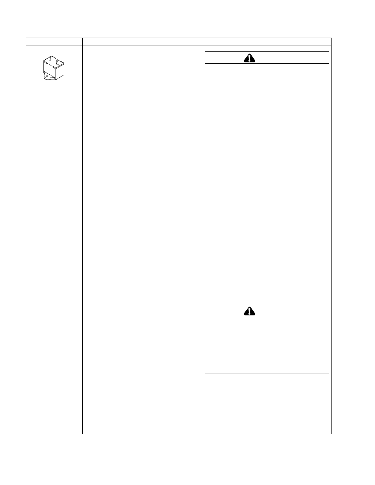
Capacitor
Condenser Condenser is a tube and wire construction
Run capacitor connects to relay terminal 3 and
L side of line.
Some compressors do not require a run
capacitor; refer to the Technical Data Sheet for
the unit being serviced.
located in machine compartment.
Condenser is on high-pressure discharge side
of compressor. Condenser function is to
transfer heat absorbed by refrigerant to
ambient.
Higher pressure gas is routed to condenser
where, as gas temperature is reduced, gas
condenses into a high pressure liquid state.
Heat transfer takes place because discharged
gas is at a higher temperature than air that is
passing over condenser. It is very important
that adequate airflow over condenser is
maintained.
Condenser is air cooled by condenser fan
motor. If efficiency of heat transfer from
condenser to surrounding air is impaired,
condensing temperature becomes higher.
High liquid temperature means liquid will not
remove as much heat during boiling in
evaporator as under normal conditions. This
would be indicated by higher than normal head
pressures, long run time, and high wattage.
Remove any lint or other accumulation that
would restrict normal air movement through
condenser.
From condenser, the refrigerant flows into a
post condenser loop that helps control exterior
condensation on flange, centre mullion, and
around freezer door. Refrigerant then flows
through the drier to evaporator and into
compressor through suction line.
To avoid electrical shock which can cause
severe personal injury or death, discharge
capacitor through a resistor before
handling.
1. Disconnect power to refrigerator.
2. Remove capacitor cover and disconnect
capacitor wires.
3. Discharge capacitor by shorting across
terminals with a resistor for 1 minute.
4. Check resistance across capacitor terminals
with ohmmeter set on “X1 K” scale.
• Good—needle swings to 0 ohms and
slowly moves back to infinity.
• Open—needle does not move. Replace
capacitor.
• Shorted—needle moves to zero and
stays. Replace capacitor.
• High resistance leak—needle jumps
toward 0 and then moves back to constant
high resistance (not infinity).
Leaks in condenser can usually be detected by
using an electronic leak detector or leak
detection fluid. Look for signs of compressor oil
when checking for leaks. A certain amount of
compressor oil is circulated with refrigerant.
Leaks in post condenser loop are rare because
loop is a one-piece copper tube.
For minute leaks:
1. Separate condenser from rest of refrigeration
system and pressurize condenser up to a
maximum of 235 PSI with a refrigerant and
dry nitrogen combination.
2. Recheck for leaks.
To avoid personal injury or death from sudden
eruption of high pressure gases, observe the
following:
Protect against a sudden eruption if high
pressures are required for leak checking.
Do not use high pressure compressed
gases in refrigeration systems without a
reliable pressure regulator and pressure
relief valve in the lines.
WARNING
WARNING
28
Component Description Test Procedures
Overload/Relay
Ice maker
ECM condenser
motor
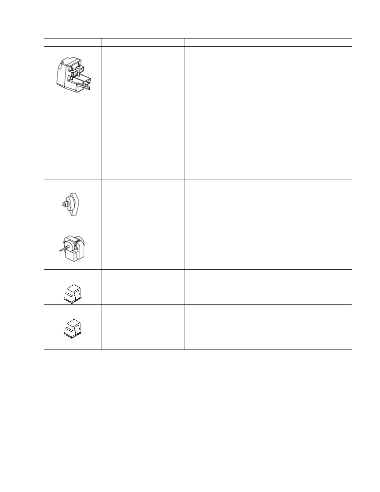
Evaporator fan
motor
When voltage is connected
and relay is cool, current
passes through relay to start
winding.
After a short time, current
heats the resistor in relay and
resistance will rise blocking
current flow through relay.
Start winding remains in the
circuit through run capacitor.
Solid state relay plugs directly
on compressor start and run
terminals. Relay terminals 2
and 3 are connected within
relay. Run capacitor is
connected to relay terminal 3.
L2 side of 120 VAC power is
connected to relay terminal 2.
See “Ice Maker” section for
service information.
Condenser fan moves cooling
air across condenser coil and
compressor body.
Condenser fan motor is in
parallel circuit with
compressor.
Evaporator fan moves air
across evaporator coil and
throughout refrigerator
cabinet.
1. Disconnect power to the refrigerator.
2. Remove relay cover and disconnect leads.
Check resistance across terminals 2 and 3 with an ohmmeter:
3.
Normal = 3 to 12 ohms
Shorted = 0 ohms
Open = infinite ohms
Check resistance across coil.
1. Disconnect power to unit.
2. Disconnect fan motor leads.
3. Check resistance from ground connection
solder. Trace to motor frame must not exceed .05
ohms.
Fresh food light
switch
Freezer
light/interlock switch
Single pole, single throw
switch completes circuit for
light when door is open.
Single pole, Double throw
switch completes circuit for
light when door is open.
Completes circuit for
dispenser when door is
closed.
4. Check for voltage at connector to motor with unit in
refrigeration mode and compressor operating.
Check resistant across terminals.
Switch arm depressed
“NO” terminals Open
Switch arm up
“NO” terminals Closed
Check resistant across terminals.
Switch arm depressed
“NO” terminals Open
”NC” terminals Closed
Switch arm not depressed
“NC” terminals Open
“NO” terminals Closed
321023
29
321023
Component Description Test Procedures
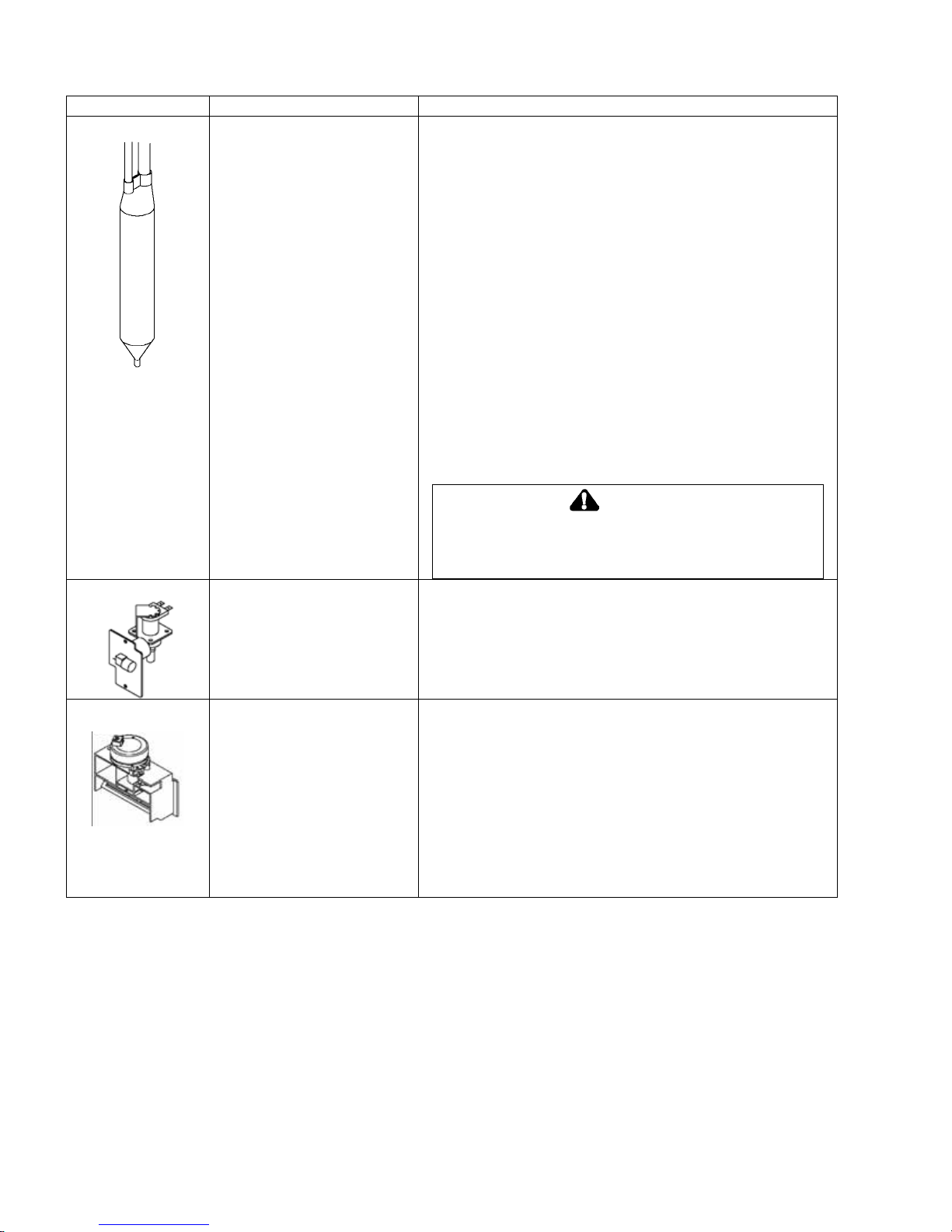
Drier
Drier is placed at post
condenser loop outlet and
passes liquefied refrigerant to
the capillary.
Desiccant 12grams XH9.
Long tail drier P/no 814843P.
Drier must be changed every time the system is opened for
testing or compressor replacement.
Before opening refrigeration system, recover HFC134a
refrigerant for safe disposal.
1. Cut drier out of system using the following
procedure. Do not unbraze drier.
2. Applying heat to remove drier will drive moisture into the
system.
3. Score capillary tube close to drier and break.
4. Reform inlet tube to drier allowing enough space for large
tube cutter.
5. Cut circumference of drier 32mm below condenser inlet tube
joint to drier.
6. Remove drier.
7. Apply heat trap paste on post condenser tubes to protect
grommets from high heat.
8. Unbraze remaining part of drier. Remove drier from system.
9. Discard drier in safe place. Do not leave drier
with customer. If refrigerator is under warranty, old
drier must accompany warranty claim.
WARNING
To avoid death or severe personal injury, cut drier at correct
location. Cutting drier at incorrect location will allow
desiccant beads to scatter. If spilled, completely clear area
of beads.
Water valve
Controls water flow to the
icemaker.
Controlled by thermostat in
icemaker.
See Ice Maker Section for
further information.
Check resistance across coil windings.
Electric damper
control
Damper control balances the
air delivery between provision
and freezer compartments
providing temperature control
for the fresh food
compartment.
The Electrical voltage
activates damper control and
the door closes, restricting
flow of air from freezer
compartment to fresh food
compartment.
Check resistance across terminals.
If no resistance across terminals replace damper control.
Can be checked in Diagnostic
30
 Loading...