


DUAL
INSTALLATION INSTRUCTIONS
Framed and Frameless Cabinetry
ActiveSmart™ Integrated Door Drawer Refrigerator
RS36W80 models
US CA
www.fisherpaykel.com
www.dcsappliances.com
845689 A 08.16


1 SAFETY AND WARNINGS
2 DUAL INSTALLATION
!
WARNING!
This appliance is top-heavy and must be secured to prevent the
possibility of tippingforward.
To ensure that the appliance is stable under all loading conditions,
theanti-tip bracket and fittings supplied must be installed according
tothe following installation instructions by a professional installer.
Dual installation refers to the joining of 1 x RS36W80R model with 1 x RS36W80L model.
RS36W80R MODELS RS36W80L MODELS
RS36W80RJ FP RS36W80LJ FP
RS36WRU FP RS36W80LJC DCS
RS36W80RJC DCS
RS36W80RUC DCS
This booklet refers to left hinge and right hinge products.
IMPORTANT!
Each refrigerator will need its own water supply with shut off valve. If a splitter is used
to supply each refrigerator with water from one water supply, we recommend that a solid
brass type be used.
If a dual power outlet is used, make sure the outlet is suitable for two right angled plugs.
Extension cords should not be used in the dual installation.
IMPORTANT!
This booklet is supplementary to your separate ‘Installation instructions’ booklet which is
supplied with your appliance. Included in this booklet are instructions which are unique
to dual installation. For correct and complete installation of your appliance(s) follow the
‘Installation instruction’ booklet supplied with your appliance.
IMPORTANT!
SAVE THESE INSTRUCTIONS
The models shown in this installation guide may not be available in all markets and are subject to change at any time. For current details about model and specification availability in your country, please go to
our website www.fisherpaykel.com or www.dcsappliances.com or contact your local Fisher & Paykel dealer.
1
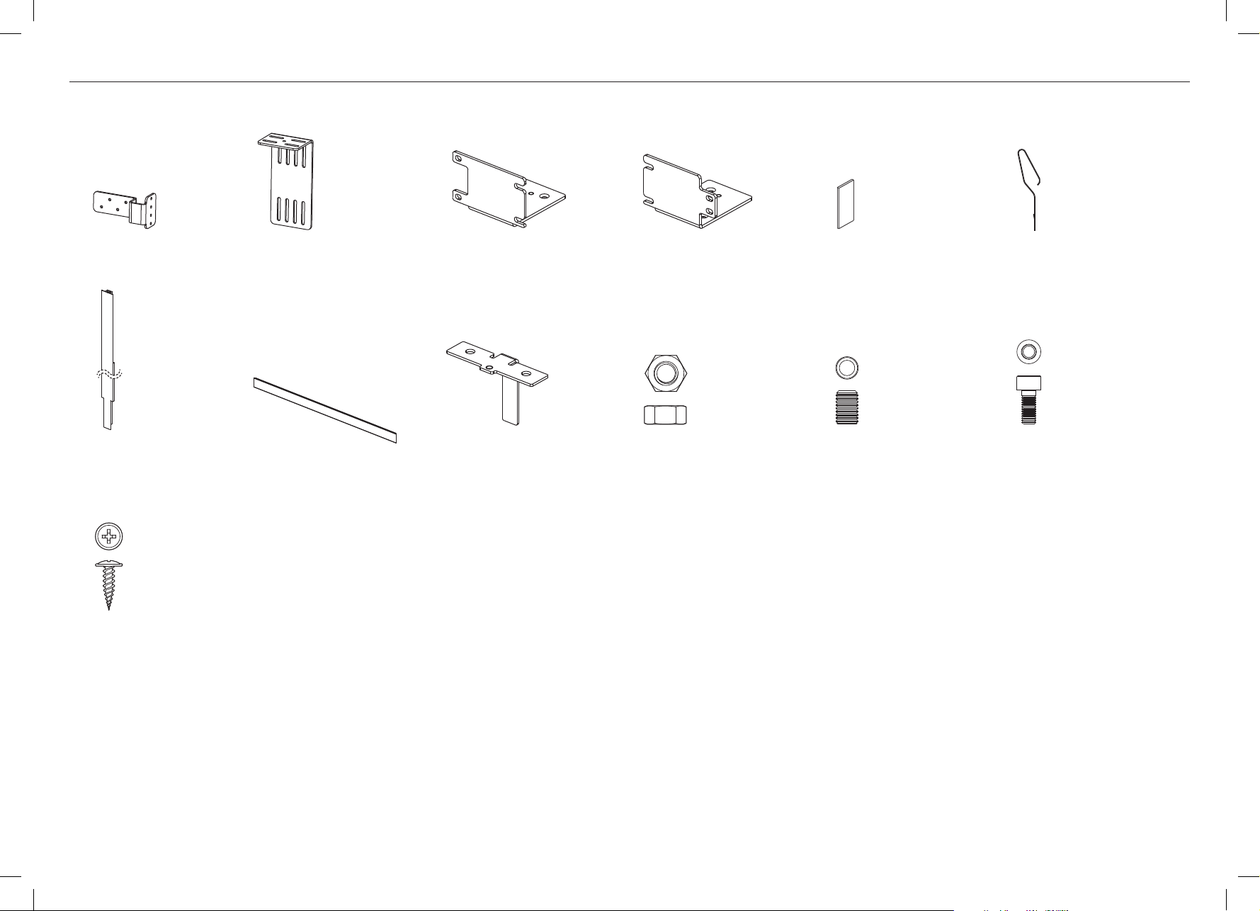
Included with the Dual Install kit (24641).
3 COMPONENTS LIST
Joiner bracket
(1)
Center trim
(1)
#8 x 16 mush
washer screw
(5)
Alcove fixing bracket
(1)
Toe kick
(1)
Right hinge product
alcove bracket
(1)
Bottom joiner bracket
(1)
Left hinge product
alcove bracket
(1)
M8 nut
(1)
Foam pads
(6)
M8 set screw
(1)
Spring clips (provided with
the appliance)
(6)
M5 x 12 Socket head cap screw
(11)
2

4 ALCOVE DIMENSIONS
A
B
ALCOVE DIMENSIONS inches (mm)
Overall height of alcove 84” (2134)
A
Overall width of alcove 72” (1829)
B
5 ATTACHING FOAM PADS
Measure and attach foam pads to three locations down the right side of the left hinge
1
product. (Align the top of the foam pad to your measurement mark. Align the side of the
foam pad with the front edge of the cabinet).
2” (50mm) from the cabinet top.
35” (890mm) from the cabinet top.
13” (50mm) from the floor.
Repeat on the left side of the right hinge product.
IMPORTANT!
To ensure good fit of joiner trim, foam pads should be placed at identical heights on left
hinge and right hinge products.
2” (50mm)
35” (890mm)
13” (50mm)
3

6 REMOVING HINGE BRACKET AND FITTING ALCOVE BRACKET
We have recommended starting with the left hinge product, then repeating the process on the right hinge product.
Removing hinge bracket
The following steps show how to remove the hinge bracket (non hinged side) and fit the
alcove bracket. This process is required on both left hinge and right hinge products.
<1/4” (6mm)
Top trim
Ensure the distance between the end of the top trim and the side of the cabinet is no
1
greater than 1/4” (6mm). If distance is greater than 1/4” (6mm), loosen the pan head Phillips
screws at the back of the trim and shift the trim sideways to suit.
On the right hand side (when facing the product) loosen the M5 x 10 pan head Phillips top
2
trim attachment screws. Shift screws towards the center of the trim, (refer to A).
Remove the right hinge bracket from the left hinge product by unscrewing the countersunk
3
Phillips head screws with a Phillips head screwdriver (refer to B).
Fitting alcove bracket
Screw the front two M5x8 countersunk Phillips screws (refer to C). Check that the top face
4
of the front trim is parallel to the product.
Shift M5x10 pan head Phillips trim attachment screws into the slots in the alcove bracket,
5
(refer to D).
– If you are not satisfied that the front trim is parallel to the product, screw the jacking
screw supplied: M5x12 Socket head cap screw (refer to E) to adjust the trim position.
Once you are satisfied that the front trim is parallel to the product, secure the alcove bracket
6
with the third countersunk screw (refer to F).
C
D
F
B
E
A
Repeat process of removing hinge bracket and fitting alcove bracket on the right
hinge product.
4

7 ATTACHING TOP JOINER BRACKET AND ALCOVE FIXING BRACKET TO ALCOVE
Use M5x12 Socket head cap screws to connect the top joiner bracket to the alcove
1
fixingbracket.
– For 80” installation, use the upper slots of the alcove fixing bracket (refer to A).
– For 84” installation, use the lower slots of the alcove fixing bracket (refer to B).
A
B
Measure the width of your alcove. Mark a line in the center of the cavity, on the ceiling.
2
72” (1829mm)
For flush installation measure 41/4” (108mm) back from the front face of the adjacent
3
cabinetry doors (refer to C). Using #8 x 16 mush washer screws (4), align and fix the joiner
bracket to the center of the alcove (refer to D).
– Face1 should be 41/4” (108mm) back.
– Face 2 should be lined up with the center of the alcove.
For proud installation, the joiner bracket should sit forward.
– Face 1 should be 41/4” (108mm) - x.
(x = distance the product sits proud).
– Face 2 should be lined up with the center of the alcove.
Loosely fix the screws into the center of each slot to enable adjustment in the joiner bracket.
WARNING!
Ensure anti tip brackets are fitted at this stage (refer to separate ‘Installation instructions’
booklet supplied with your appliance).
IMPORTANT!
Door panels must be fitted to doors at this stage (refer to separate ‘Installation
instructions’ booklet supplied with your appliance).
WARNING!
Do not open doors.
C
41/4” (108mm) = flush installation
41/4” (108mm) - x = proud installation
D
84” (2134mm)
41/4” (108mm) = flush installation
41/4” (108mm) - x = proud installation
x
At this stage connect to water and electrical supply as per the ‘Installation instructions’
booklet supplied with your appliance.
Face 1
Face 2
WARNING!
Failure to follow the instructions can lead to serious injury or death.
5

8 LOCATION OF PRODUCTS INTO ALCOVE — RIGHT PRODUCT
Roll the right hinge product into the right hand side of the alcove until the product makes
1
contact with the joiner bracket.
IMPORTANT!
For flush installation: check for flushness of the product with the surrounding cabinetry
(refer to separate ‘Installation instructions’ booklet supplied with your appliance) on
how to achieve flushness.
Adjust the product height (refer to separate ‘Installation instructions’ booklet supplied with
2
your appliance).
Screw two M5 x 12 Socket head cap screws to connect the alcove bracket to the joiner
3
bracket (refer to A).
If the product is not flush, further loosen the top screws of the alcove attachment bracket
4
if required and move the bracket in a forward to back motion to suit (refer to B).
Recheck product flushness (refer to separate ‘Installation instructions’ booklet supplied
5
with your appliance). Once satisfied with flushness, tighten top screws fix an additional
#8 x 16 mush washer screw (refer to C).
A
B
C
6

9 LOCATION OF PRODUCTS INTO ALCOVE — LEFT PRODUCT
IMPORTANT!
Open the door of the right hinge product.
Roll the left hinge product into the left hand side of the alcove until the product makes
1
contact with the joiner bracket (refer to A).
IMPORTANT!
For flush installation: check for flushness of the product with the adjacent product (refer
to separate ‘Installation instructions’ booklet supplied with your appliance on how to
achieve flushness).
A
Open the left hinge product door to access the brackets (refer to B).
2
Adjust the product height (as per the separate ‘Installation instructions’ booklet supplied
3
with your appliance), so holes in the top trim are in line with the holes in the joiner bracket
(refer to C).
– Note: for clarity of drawing, top trims are not shown.
Screw two M5 x 12 Socket head cap screws to fix left hand top trim to the joiner bracket
4
(refer to C).
B
C
7

!0 PREPARING FOR CENTER TRIM
Remove the center* M10 x 65 Socket head cap screws from the base of the products
1
(refer toA)
*Remove the right screw from the left hinge product.
*Remove the left screw from the right hinge product.
Attach the bottom joiner bracket using M10 x 65 Socket head cap screws (refer to B).
2
A B
For 80” products, cut center trim using the same method as instructed for side trims
3
(refer to separate ‘Installation Instructions’ booklet supplied with your appliance).
Mark out three locations for the spring clips along the center trim to match foam pad
4
locations on cabinet.
Insert right hand spring clip into the center trim channel (refer to C).
5
IMPORTANT!
Ensure the bottom of the right hand spring clip is located on the right hand side of the
channel.
Insert the left hand spring clip into the center trim channel (refer to D).
6
Before pushing the left hand spring clip all the way into the trim, squeeze the two spring
7
clips together and push home. You will hear the spring clips engage into the trim (refer to E).
Repeat for the remaining two locations on the center trim.
C
D E
CLICK!
8

IMPORTANT!
Open both refrigerator doors.
!1 ATTACHING THE CENTER TRIM AND TOE KICK
Installing toe kick
6
Unscrew the toe kick bracket screws mid-way, and bring forward (refer to D and E).
Bring the center trim in front of
1
the gap between the two products
(refer to A).
A
Starting from the upper spring clips, squeeze the clips to
2
slot between the two products (refer to B).
Repeat on the middle and then the lower clips.
3
Using the palm of your hand, push trim all the way down
4
the length of the product.
Repeat this process for both products.
D
E
Place toe kick over the brackets and position
7
the outer brackets until flush with surrounding
cabinetry. Use the folded edge of the supplied
toe kick or another suitable straight edge
to align the inner brackets. Once satisfied,
remove the toe kick.
B
Screw the M8 set screw into the threaded hole of the
5
bottom joiner bracket to support the middle trim. This
maintains the height position of the trim. Once you are
satisfied with the location of the middle trim, use the M8
nut to lock the set screw into location (refer to C).
Tighten the toe kick bracket screws to lock brackets into position and remove the backing
8
from the Velcro strip (refer to F). Attach the toe kick to the adhesive surfaces.
C
F
9

www.fisherpaykel.com
www.dcsappliances.com
The product specifications in this booklet apply to the specific products
and models described at the date of issue. Under our policy of continuous
product improvement, these specifications may change at any time. You
should therefore check with your Dealer to ensure this booklet correctly
© Fisher & Paykel Appliances 2016. All rights reserved.
describes the product currently available.
US CA
845689 A 08.16
 Loading...