

Page 1

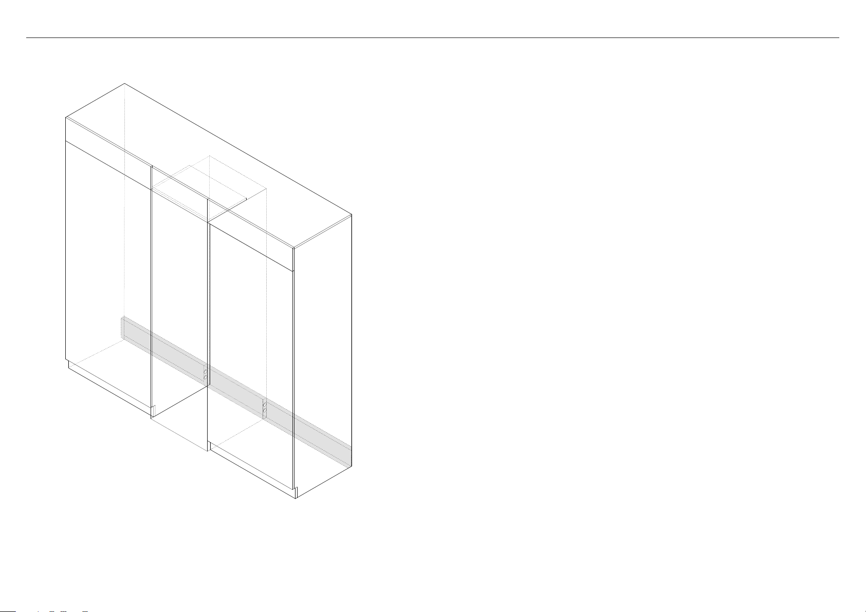
INTEGRATED COLUMN
REFRIGERATOR FREEZER
RS2484WR, RS2484WL,
RS3084WR & RS3084WL
models
INSTALLATION GUIDE
US CA
86026B0.20
Page 2

Page 3

CONTENTS
Safety and warnings 4
Integrated columns — refrigerator–freezer 5
Check your appliance 6
Moving your appliance 7
Before installation 8
Supplied parts 9
Required parts 11
toe kick panel 11
Door panel set 12
Door and drawer handle kits 12
Hinge change kit 13
Product dimensions — RS24 model 14
Cavity dimensions — RS24 model 15
Door panel dimensions — RS24 model 16
Custom door panel install dimensions — rs24 model 17
Door clearance — RS24 model 18
Drawer clearance — RS24 model 19
Toe kick dimensions — RS24 model 20
Toe kick install options 21
Product dimensions — RS30 model 22
Cavity dimensions — RS30 model 23
Door panel dimensions — RS30 model 24
Custom door panel install dimensions — RS30 model 25
Door clearance — RS30 model 26
Drawer clearance — RS30 model 27
Toe kick dimensions — RS30 model 28
Dual install options 29
Cavity dimensions — RS24 + RS24 dual install 30
Cavity dimensions — RS24 + RS30 dual install 31
Cavity dimensions — RS30 + RS30 dual install 32
Toe kick panel dimensions — dual install 33
Power supply dimensions 34
Electrical specification 35
Plumbing specification 35
Install anti-tip bracket 36
Connect water and power supply 38
Position and alignment in cabinetry 40
Secure appliance to cabinetry 45
Remove hanging brackets 46
Install door and drawer panels 47
Install locking bracket 51
Install adjustment brackets 51
Install toe kick panel 52
Install toe kick grilles 53
Install top trim 53
Install water filter 54
Install air flow divider 55
Install cabinet side trims 56
Install door and drawer side trims 57
Dual installation 58
Change the door hinges (optional) 64
Final checklist 70
SAVE THESE INSTRUCTIONS
The models shown in this installation guide may not be available in all markets and are subject to change at any time. For current details about model and specification availability in your country, go to our
website fisherpaykel.com or contact your local Fisher & Paykel dealer.
3
Page 4
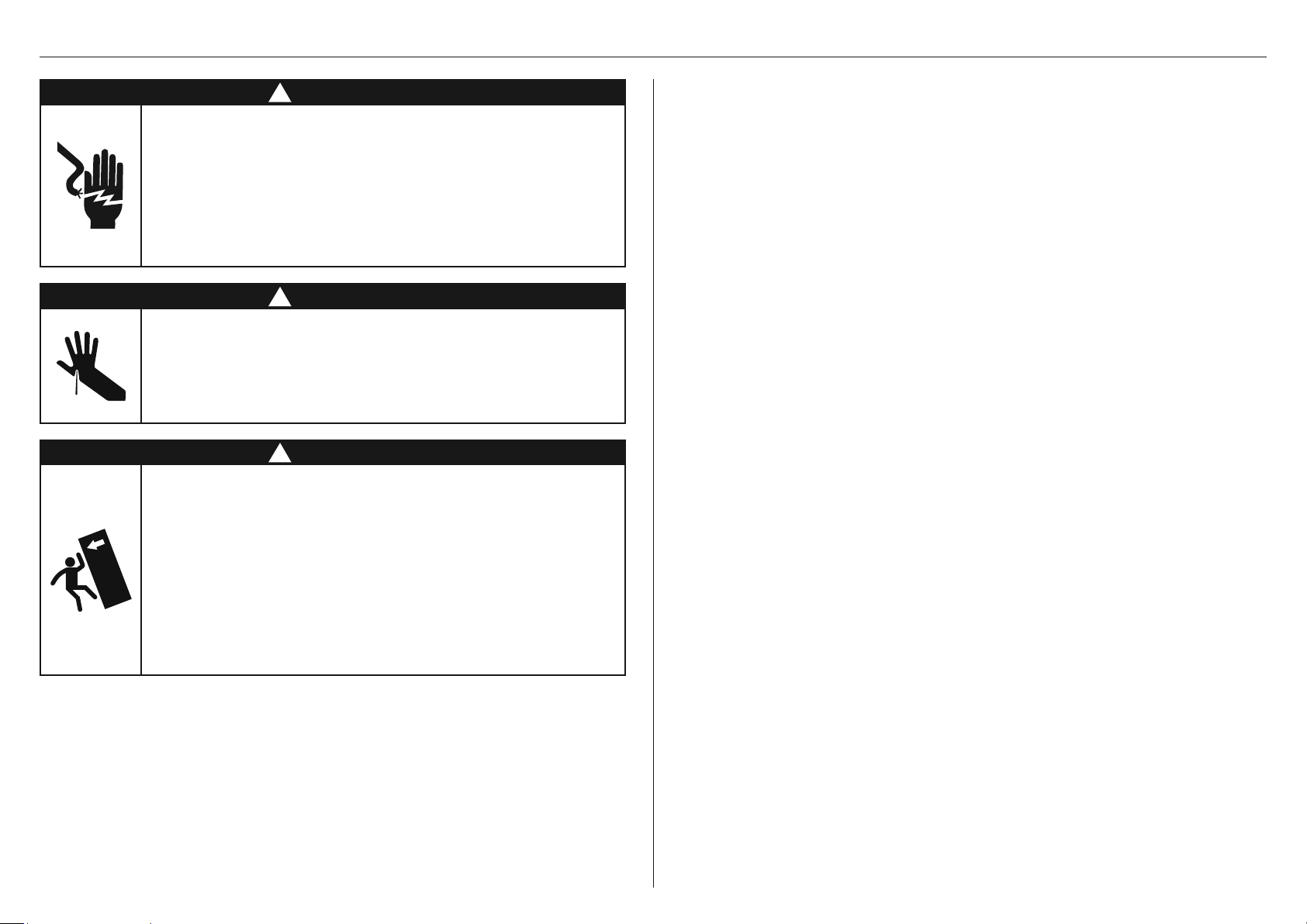
SAFETY AND WARNINGS
!
WARNING!
Electric Shock Hazard
Read and follow the safety and warnings
outlined in this installation guide before
operating this appliance.
Failure to do so can result in death, electric
shock, fire or injury topersons.
!
WARNING!
Cut Hazard
Take care—panel edges are sharp.
Failure to use caution could result in injury
or cuts.
!
WARNING!
This appliance is top-heavy and must
be secured to prevent the possibility of
tippingforward.
To ensure that the appliance is stable under
all loading conditions, theanti-tip bracket
and fittings supplied must be installed
according tothe following installation steps
by a professional installer.
WARNING!
To avoid hazard, follow these instructions carefully before installing or using thisappliance.
z
Please make this information available to the person installing the appliance.
z
Assume all electrical parts are live.
z
Disconnect power supply before servicing and installation.
BEFORE INSTALLATION
z
The appliance has front and rear rollers for moving the appliance forward and backward.
Do not move the appliance sideways to avoid damaging the rollers or the floor
covering/surface.
z
Ensure your appliance is not exposed to any heat generating appliance eg cooktop, oven
or dishwasher.
z
The appliance must be installed by a qualified installer, or Fisher & Paykel trained and
supported service technician to avoid faulty electrical and plumbing connections.
z
All connections for electrical power and earthing must comply with local codes and
ordinances and be made by licensed personnel when required.
z
Avoid installation of the appliance/s near a ground fault circuit interrupter (GFCI).
z
Ensure the appliance is installed properly. Improper installation that results in appliance
failure is not covered under the appliance warranty.
UNPACKING
z
The appliance is heavy and requires at least twopersons to move and install.
z
Remove the installation kit (internal box) and trims kit (external box) while the product is
still on the pallet.
z
Avoid scratching the surface of your appliance when moving or installing.
z
Keep the appliance stable and door closed to prevent tipping over when moving to the
installation location.
z
Ensure the feet of the appliance are retracted before moving to the installation location.
z
If the appliance is damaged, contact your Fisher & Paykel dealer.
z
Ensure all components and accessories are complete. Refer to 'Before installation' page.
z
Record the default Wifi password, and the model and registration numbers for future
servicing or repair of your appliance.
ELECTRICAL/PLUMBING
z
Electrical and water supply connections for these appliances must be located in an
adjacent area or unit (cabinet or cupboard) that are easily accessible in case of repair or
disconnection.
z
Ensure an isolating switch is available if electrical connection is not accessible.
INSTALLATION
Cavity preparation
z
The anti-tip bracket and fittings supplied must be fitted tothe wall of the finished
enclosure to withstand a 225lb/100kg load.
z
Ensure that the anti-tip bracket is installed correctly to prevent the possibility of the
appliance tipping forward when the door is open.
4
Page 5
SAFETY AND WARNINGS
Positioning inside the cabinetry
z
Ensure the door of the appliance is closed when rolling into thecabinetry.
z
Ensure the power cord is not run over or damaged when rolling the product into
the cabinetry.
Aligning inside the cabinetry
z
For flush installation, ensure the door panels are installed flush with cabinetry front surface.
Ensure the appliance is properly is centred.
z
All four corners of the appliance must be supported firmly on the floor to eliminate any
movement. Installing the appliance on a soft, uneven, or not level floor may cause twisting
and poor door sealing.
Fixing inside the cabinetry
z
Use low speed, low torque setting when using a powered driver for the screws when fixing
or aligning the product.
z
Make sure to remove the depth alignment brackets before fixing theappliance inside the
cabinetry.
z
Open the appliance door to remove the alignment brackets from both sides of the
appliance, and then re-tighten the screws.
Installing the door panel
Stainless steel panel
z
Protect the finish of the Fisher & Paykel Stainless Steel door panels from any scratch
or damage.
z
Remove the blue tape attached to inner edges of the door panels after the handles are
installed.
z
We recommend to load the shelves in the appliance door with weights to ensure an
accurate door panel gap width.
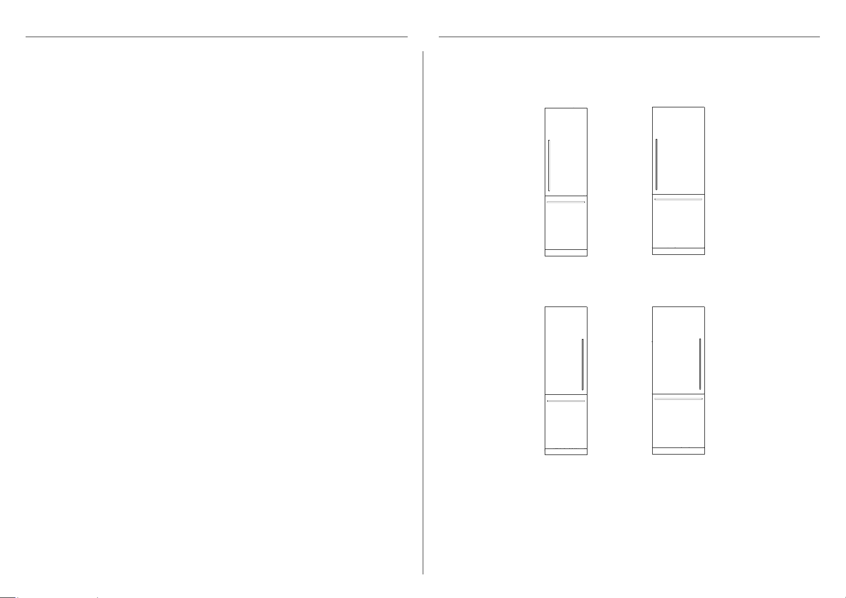
INTEGRATED COLUMNS — REFRIGERATOR–FREEZER
24” (610mm) 30” (762mm)
RS2484WR
RS3084WR
Custom panel
z
If using Custom door panels, ensure they are prepared as per 'Custom door panel install
dimensions' section.
z
The thickness of the custom door panel can vary as long as the screws do not penetrate
beyond the full depth of the door panel, and as long as the overall weight of the panel
does not exceed 55lb/25kg.
z
Do not place the handle holes in marked areas to avoid clashing with panel
attachment brackets.
z
Minimum panel thickness where screw hole is drilled must be 16mm.
Switching the door hinge (optional)
z
Door hinges are interchangeable for each model. A hinge change kit is available and can be
purchased separately if you prefer to change from ‘right hand hinge’ to ‘left hand hinge’ or
vice versa.
RS2484WL
RS3084WL
5
Page 6
CHECK YOUR APPLIANCE
z
Ensure you follow the unpacking steps printed on the packaging box of your appliance.
z
Check that your appliance is the correct model as per your order.
z
Check that the components and install kits are complete.
A
B
1
2
34
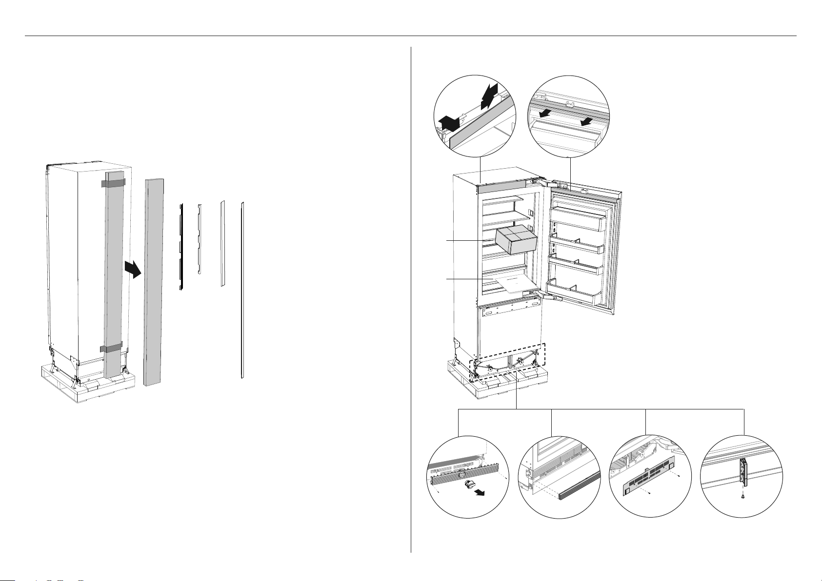
Remove external box (trims kit)
from the back of the appliance.
The box contains:
1 Top door panel side extrusion
2 Bottom drawer panel
side extrusion
3 Bottom drawer top trim
4 Cabinet side trim
C
D
Remove installation kit, miscellaneous
items pack and pre-installed parts.
Keep all components to use later.
A Top trim
B Top door extrusion
C Installation kit
D Miscellaneous items pack and
water filter kit
E Top grille and water filter tool
F Bottom grille
INTEGRATED
CO
LUMNS
RS46
2
1F
,
RS6121F
R
S
612
,
R
1S & RS7
S76
2
1F
,
621S mod
els
INS
T
A
LL
A
TI
O
N
GUIDE
N
Z
AU
G
B
E
U
8
4
9
1
6
4
B
10
.
18
G Toe kick mounting plate
H Air flow divider
e hg
f
6
Page 7
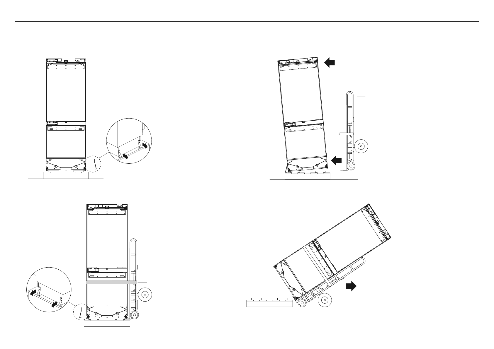
z
Follow the steps below to move your appliance to the install location.
z
Be careful when tilting the appliance forward/backward.
z
Tape the door shut to prevent opening while moving the appliance.
1 Remove the brackets from the
non-hinge side of the pallet.
MOVING YOUR APPLIANCE
Hand truck
2 Tilt the appliance slightly
forward and insert the
hand truck between
pallet and appliance.
3 Restrain the appliance
with strap and remove the
remaining brackets.
Strap
4 Tilt backward to load appliance
onto hand truck and push to
install location
7
Page 8
BEFORE INSTALLATION
Check the cabinetry
z
Check the dimensions of the cabinetry: height, width, depth, floor level, finished
alcove returns. Refer to 'Cavity Dimensions' for the correct measurements.
Check the power supply and water connections
z
Ensure that there is a separate power socket for each appliance.
z
Avoid sharing the power point with other appliances to prevent accidental switching off of
the appliance.
z
For power requirements, refer to the information on the serial plate.
z
Ensure your appliance is properly grounded (earthed).
z
Connect your appliance to an electrical supply with the fitted plug and lead.
z
If power connection is located behind the appliance, we recommend to install an isolating
switch to a location that is easily accessible to the user for repair or disconnection.
z
If water connection is behind the appliance, we recommend to connect the hose to exit at an
angle if there is not enough clearance between the cabinet wall and back of appliance.
z
Follow local codes and ordinances when installing the appliance.
8
Page 9

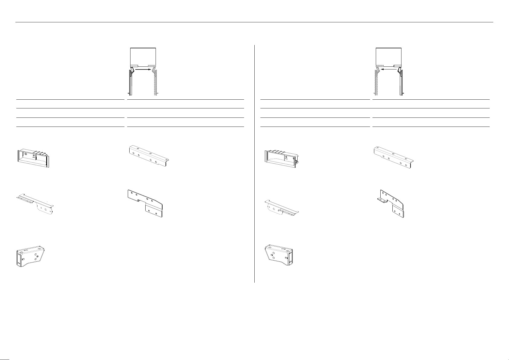
SUPPLIED PARTS
DOOR PANEL ATTACHMENT KIT INSTALL FASTENERS KIT
Side bracket
(6)
For Custom door panels:
M5x12 Cross-head screw (32)
Anti-tip bracket
(1)
Bracket slider
(6)
Side spacer bracket
(6)
ANTI-TIP BRACKET ASSEMBLY
Masonry plug
(4)
10-12x35mm crosshead screw
(5)
Depth alignment gauge
(4)
Supplied in separate bags
Hinge limiting pin
(3)
Barbed plug
(2)
MISCELLANEOUS PARTS
Air toe kick seal
(1)
8Gx16 Countersunk screw
(7)
Locking clip
(2)
9
Page 10
SUPPLIED PARTS
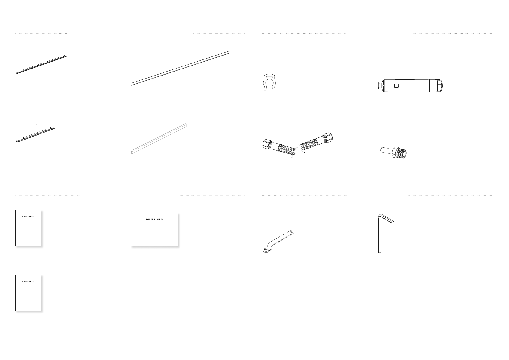
TRIMS INSTALL KIT (EXTERNAL BOX)
Top door panel side extrusion
(2)
Bottom drawer panel side
extrusion (2)
Cabinet side trim
(2)
Bottom drawer top trim
(1)
MISCELLANEOUS ITEM PACK
WATER FILTER KIT
Collet locking clip
(1)
7/16" (11mm) UNS Stainless steel braided hose
(1)
SUPPLIED TOOLS
Water filter
(1)
1/4” (6.35mm) Adaptor
(2)
INTEGRATED COLUMN
WINE CABINET
RS2484VL2K1, RS2484VR2K1,
RS6121VL2K1, RS6121VR2K1
models
USER GUIDE
US CA NZ AU GB IE SG HK
8602A09.19
User guide
(6)
SERVICE & WARRANTY
SERVICE ET GARANTIE
ΣΈΡΒΙΣ ΚΑΙ ΕΓΓΎΗΣΗ
SERVIZIO E GARANZIA
SERVICE & GARANTIE
HUOLTO JA TAKUU
SERVICE OG GARANTI
保修和维修
݉ଡ଼ڸߴঔ
Service & Warranty
(1)
10
INTEGRATED COLUMNS
WINE CABINET
RS2484VL2K1, RS2484VR2K1,
RS6121VL2K1, RS6121VR2K1
models
INSTALLATION GUIDE
US CA NZ AU GB IE SG HK
86020A09.19
Installation guide
(1)
Door spanner
(1)
M4 Hex key
(1)
Page 11
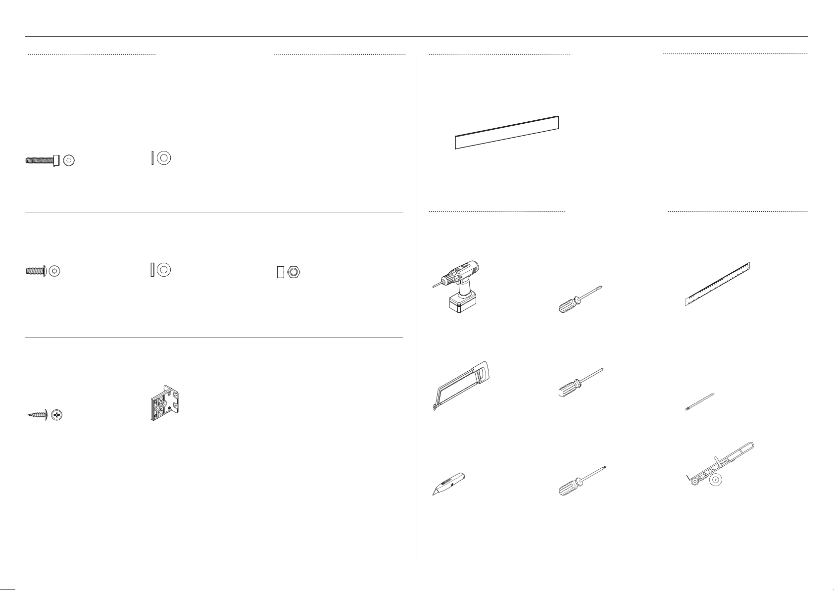
REQUIRED PARTS
INSTALL JOINER KIT TOE KICK PANEL
Used for dual or multiple installation of appliances. Can be purchased separately through an
authorised Fisher & Paykel dealer. Visitfisherpaykel.com for more information.
Top joiner fastener kit
M5x20 Cap screw
(1)
Bottom joiner fastener kit
M6x16 Washer screw
(1)
M5x16x1 Plain washer
(1)
M6x12x3.2 Plastic washer
(1)
M6 Hex nut
(1)
TOE KICK PANEL
Not supplied and can be purchased separately through an authorised Fisher & Paykel dealer.
Visitfisherpaykel.com for more information.
z
Standard toe kick height is 102mm forstandard
stainless steel door panel.
z
For Custom door panel installation, atoe kick
2"–6" (50-152mm) must be fitted andadjusted
accordingly.
z
An extra bottom grille is required for 2" (50mm)
Toe kick panel (1)
toe kick installation. You can purchase the extra
bottom grille (Part No. 847542P) online at
fisherpaykel.com.
REQUIRED TOOLS
Not supplied and must be provided by the installer.
Powered driver Flathead screwdriver Ruler
Top joiner bracket kit
8Gx16 Mush washer screw
(2)
Central spacer
(1)
Hacksaw Cross-head screwdriver Pencil
Cutter T20 star-head screwdriver Hand truck
11
Page 12
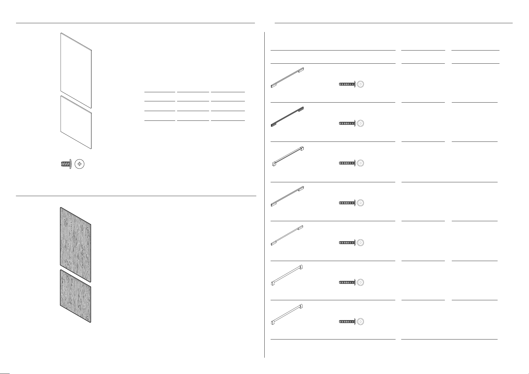
DOOR AND DRAWER HANDLE KITSDOOR PANEL SET
Not supplied and must be purchased separately through an authorised Fisher & Paykel dealer.
Visitfisherpaykel.com for more information. Select among the handle kit options below:
For SS door panels:
8Gx16 Mush washer screw (32)
Stainless steel door panel set
Not supplied and must be purchased
separately through an authorised Fisher
& Paykel dealer. Visitfisherpaykel.com for
more information..
MODEL RH LH
RS24 CA 25715 CA 25716
RS30 CA 25713 CA 25714
Custom door panel set
Supplied by customers to match their
cabinetry.
HANDLE KIT RS24 RS30
Square fine aluminum
handle (1)
Square fine black
handle (1)
Professional square
handle (1)
Square aluminum
handle (1)
Round aluminum
handle (1)
M5x25 Hex screw (4)
M5x25 Hex screw (4)
M5x25 Hex screw (4)
M5x25 Hex screw (4)
M5x25 Hex screw (4)
CA 25865 CA 25864
CA 25911 CA 25910
CA 25732 CA 25724
CA 25729 CA 25721
CA 25731 CA 25723
12
Professional round
handle (1)
Professional round
flush handle (1)
M5x25 Hex screw (4)
M5x25 Hex screw (4)
CA 25730 CA 25722
CA 25923 CA 25922
Page 13
Not supplied and must be purchased separately. Available online at fisherpaykel.com.
HINGE CHANGE KIT
MODEL LEFT HINGE TO RIGHT HINGE KIT
RS24 CA 848184P
RS30 CA 848184P
Top hinge pocket RH
(2)
K05 bottom adaptor bracket RH
(1)
Top alcove bracket RH
(1)
Bottom hinge bracket RH
(1)
K05 top adaptor bracket RH
(1)
MODEL RIGHT HINGE TO LEFT HINGE KIT
RS24 CA 848183P
RS30 CA 848183P
Top hinge pocket LH
(2)
Top alcove bracket LH
(1)
Bottom hinge bracket LH
(1)
K05 bottom adaptor bracket LH
(1)
K05 top adaptor bracket LH
(1)
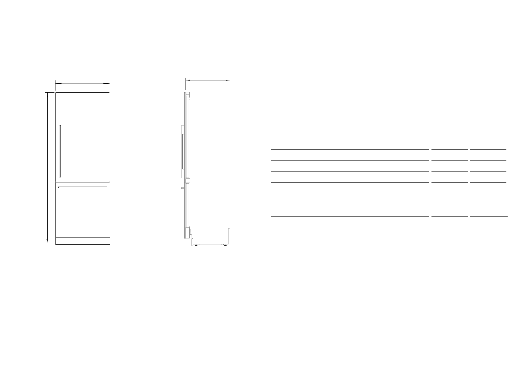
13
Page 14
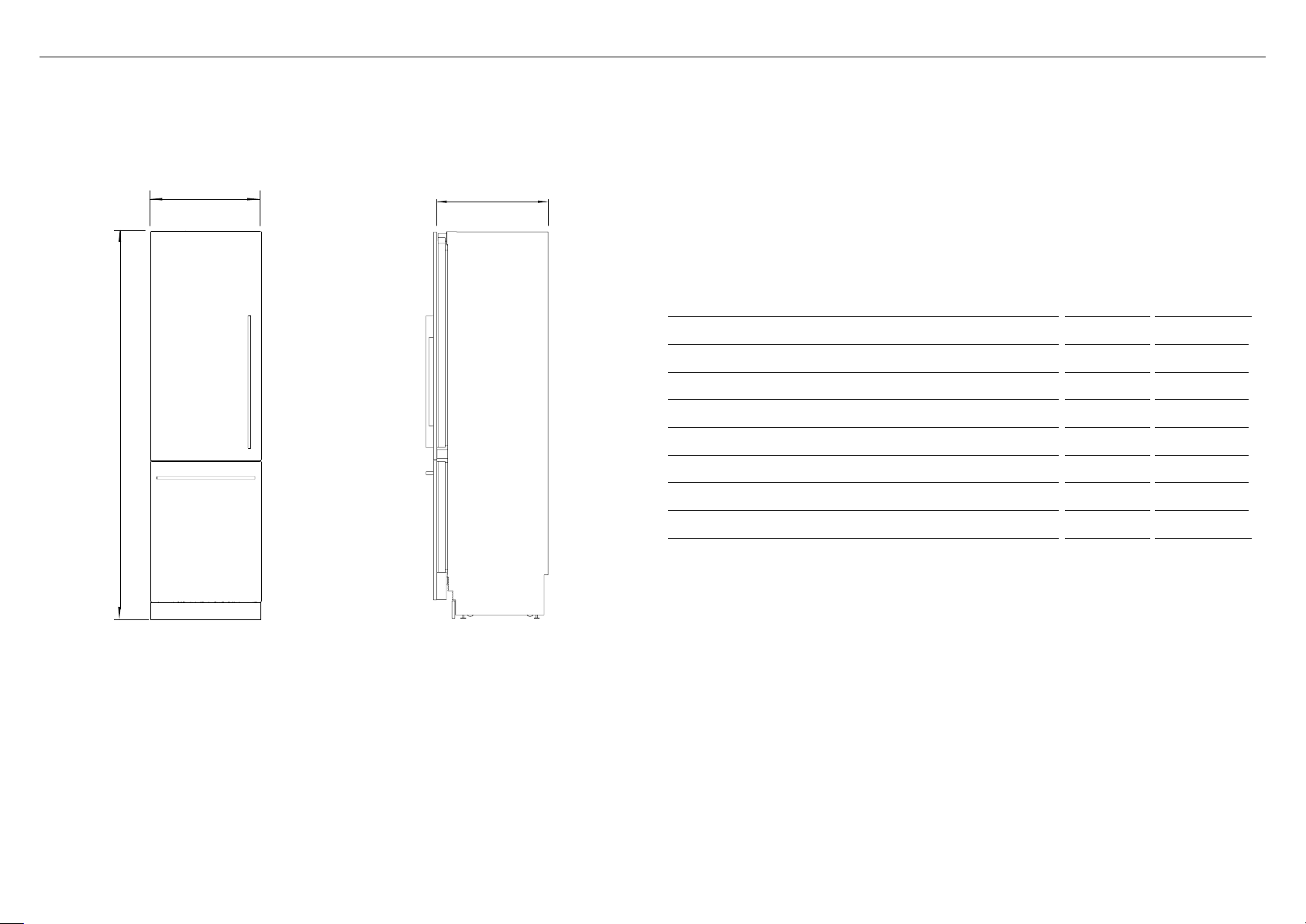
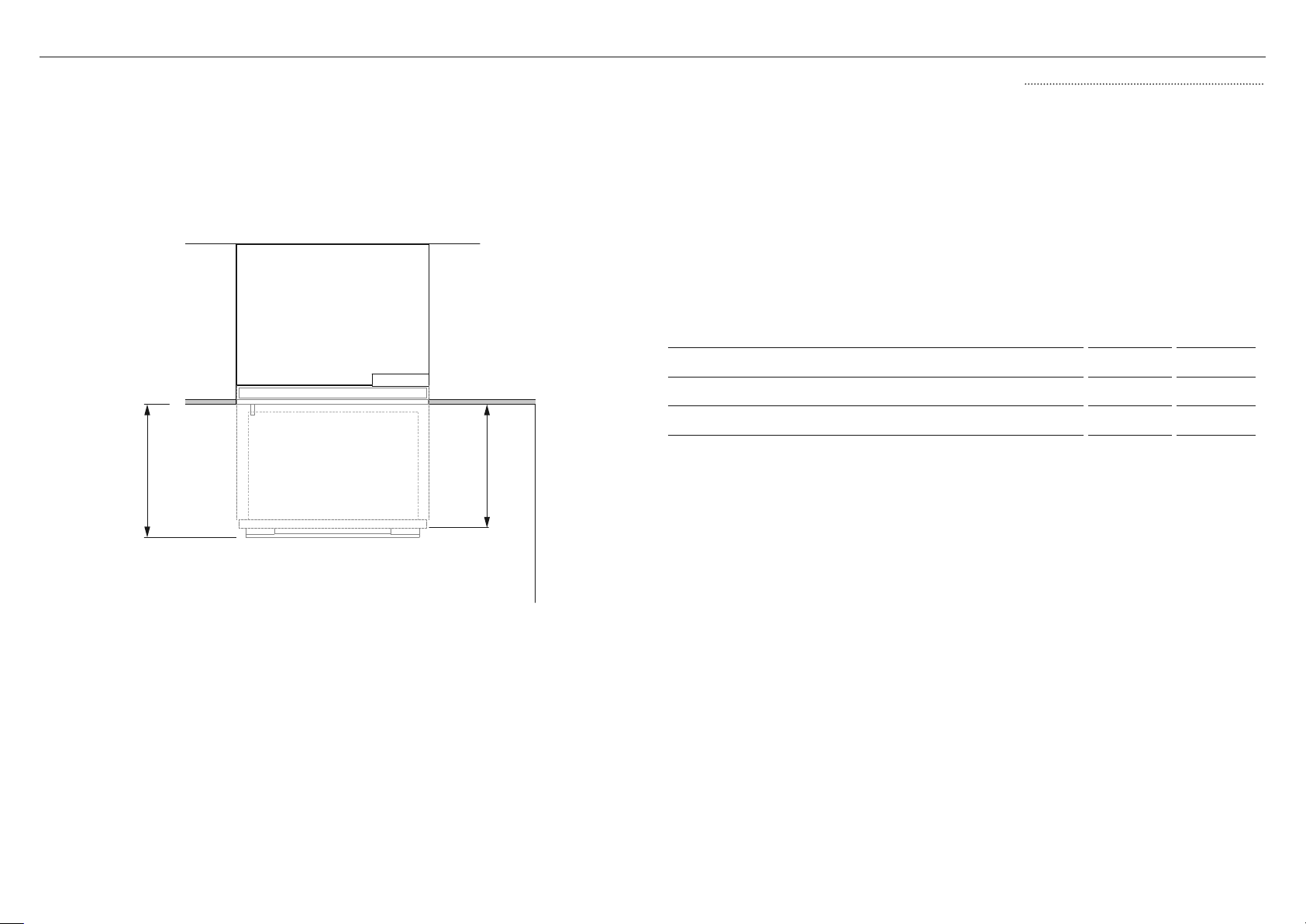
PRODUCT DIMENSIONS — RS24 MODEL
A
B
C
PRODUCT DIMENSIONS IN MM
A Overall height of product 84 2134
B Overall width of product 23 3/4 603
C Overall depth of product (excluding front door panel) 24 610
PRODUCT WEIGHT LBS KG
Weight (with packaging) 357 162
Weight (without packaging) 313 142
14
FRONT VIEW
PROFILE VIEW
Page 15
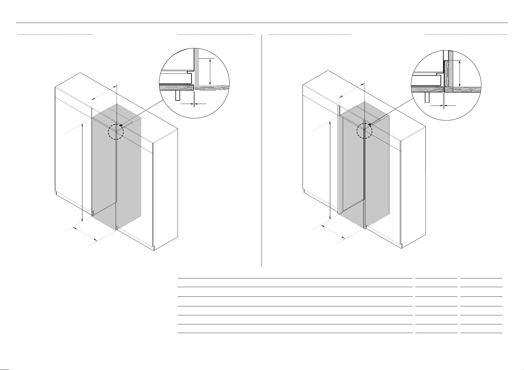
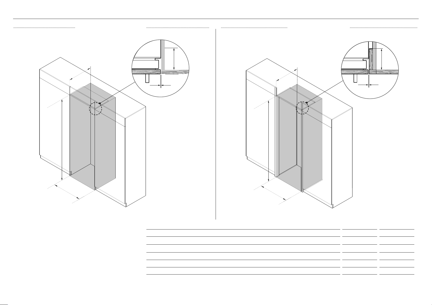
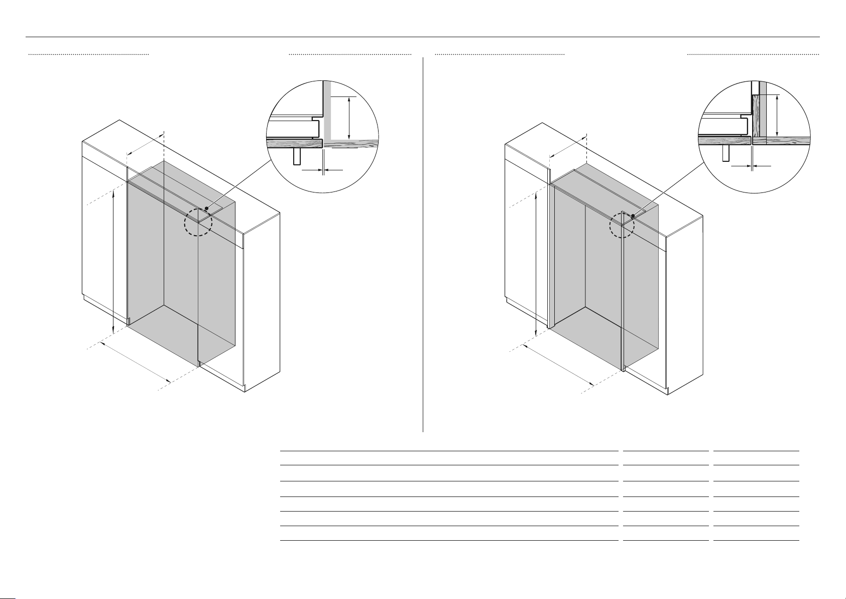
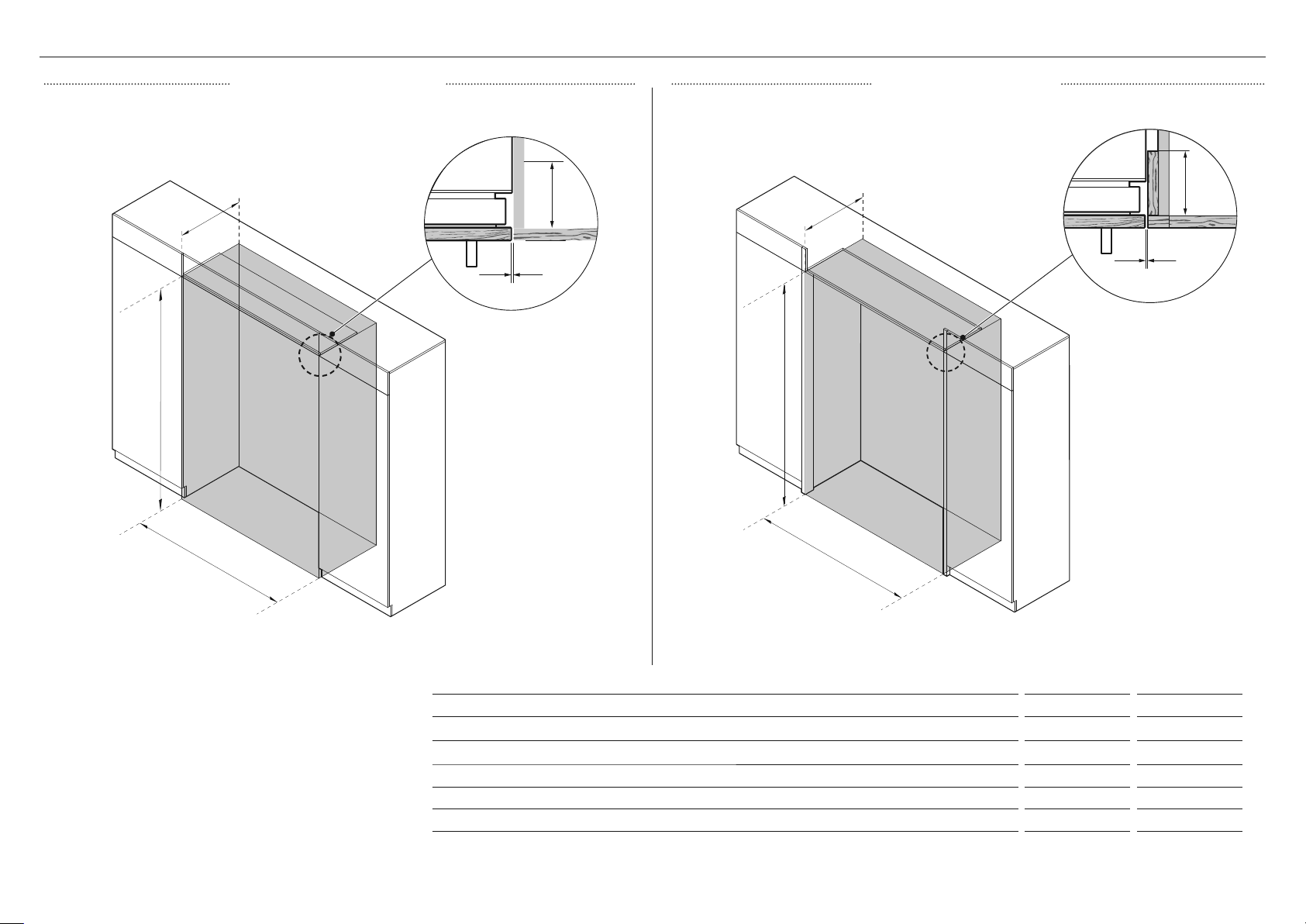
CAVITY DIMENSIONS — RS24 MODEL
FRAMELESS CABINETRY FRAMED CABINETRY
Aligns appliance flush with the cabinetry.
C
A
D
B
A
E
Aligns appliance flush with the frame of cabinetry.
E
C
D
A
B
B
DIMENSIONS IN MM
A Overall height of cavity
B Overall width of cavity
C Minimum overall depth of cavity* 25 635
D Minimum cabinetry gap clearance from edge of door panels 1/8” 3
E Minimum required finished return 4” 102
* Assumes a door panel thickness of 3/4” (19mm).
84 2134
24 610
15
Page 16
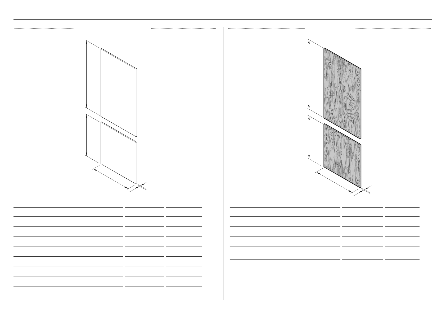
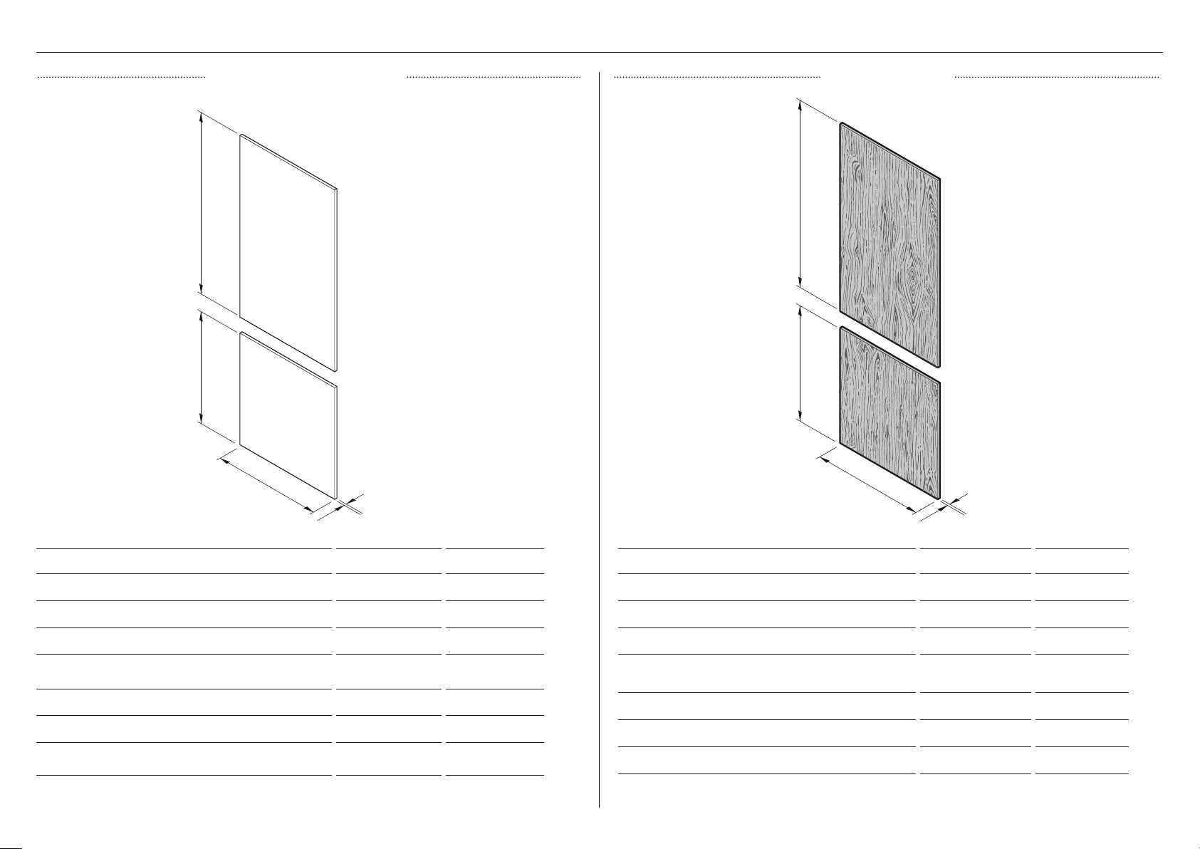
DOOR PANEL DIMENSIONS — RS24 MODEL
STAINLESS STEEL PANEL CUSTOM PANEL
A
B
C
DIMENSIONS IN MM
A Height of top door panel 49 3/8 1254
A
B
C
DIMENSIONS IN MM
A Height of top door panel 49 3/8 1254
B Height of bottom drawer panel 30 3/8 772
C Width of door/drawer panel 23 3/4 603
D Depth of door panel (excluding door handle) 3/4 19
DOOR PANEL WEIGHT LBS KG
Weight of top door panel* 20 9
Weight of bottom drawer panel* 13 6
16
B Height of bottom drawer panel 30 3/8 772
C Width of door/drawer panel 23 3/4 603
D Depth of door panel (excluding door handle)
DOOR PANEL WEIGHT LBS KG
Weight of top door panel max 34 max 15 1/2
Weight of bottom drawer panel max 21 max 9 1/2
* Maximum panel weight must not be exceeded.
min 5/8
max 1
min 16
max 25
Page 17
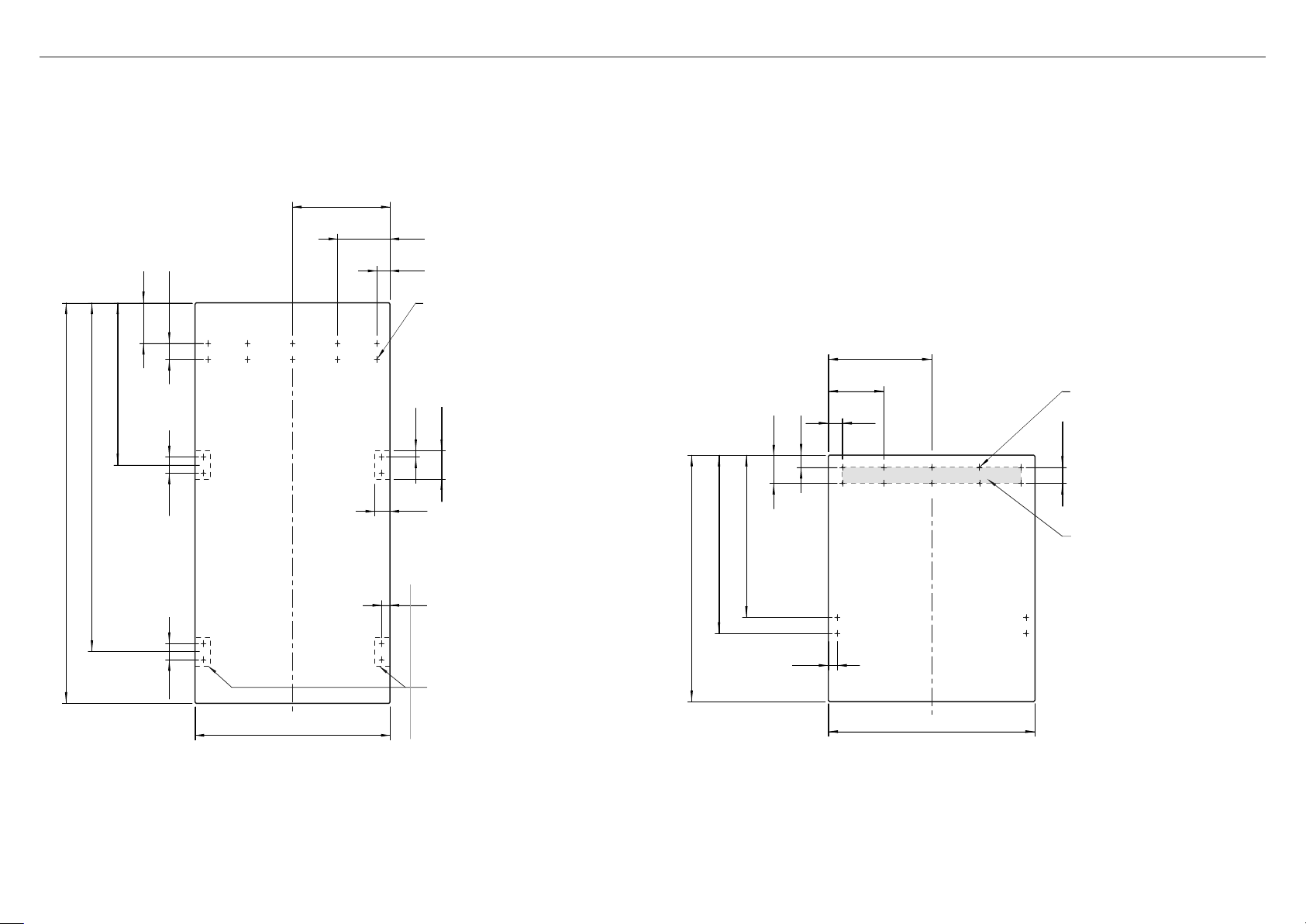
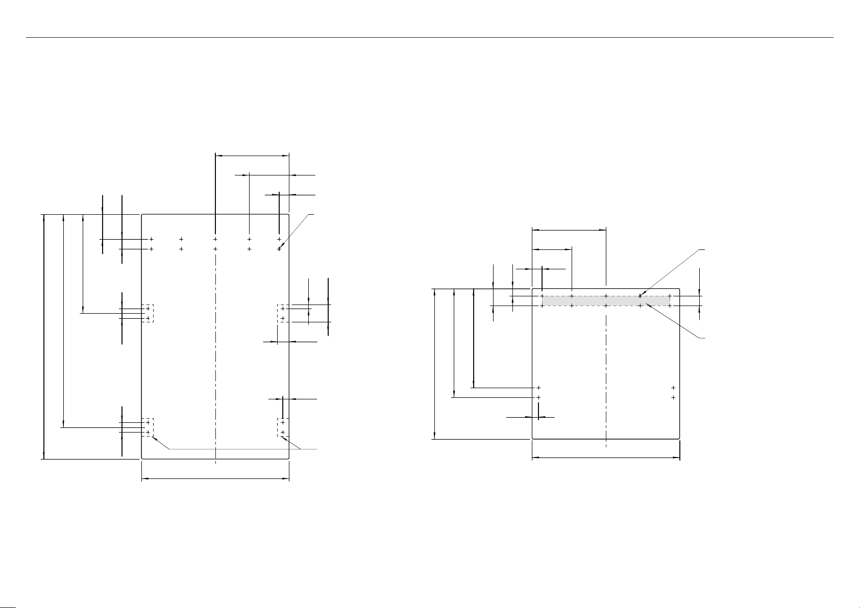
CUSTOM DOOR PANEL INSTALL DIMENSIONS — RS24 MODEL
Dimensions apply for the preparation and installation of Custom door panels. For Dwg and Dxf files of the below panel preparation download the folder on thekitchentools.fisherpaykel.com.
z
The thickness of the custom door panel can vary provided that the screws do not penetrate beyond the full depth of the door panel.
z
Measurements of screw hole locations can vary depending on the height of toe kick 50–152mm.
11 7/8" (301.6mm)
8" (203.2mm)
2" (50.8mm)
1/2" (38.m)
15" (127mm)
20" (507.8mm)
2" (50mm)2" (50mm)
Ø2mm REF
10x Pilot holes recommended
for bracket attachment.
(Do not penetrate front surface).
2" (50mm)
1 1/2" (38.1m)
3 1/2" (88mm)
11 7/8" (301.6mm)
8" (203.2mm)
2" (50.8mm)
Ø2mm REF
10x Pilot holes recommended
for bracket attachment.
(Do not penetrate front surface).
2" (50mm)
43" (1092mm)
49 3/8" (1254mm)
23 3/4" (603.2mm)
TOP PANEL—REAR VIEW
Ensure handle is mounted
2 9/16" (65mm) from edge
to center of panel — this will
avoid interference with bracket.
1 1/4" (32.6mm)
30 3/8" (771.5mm)
20" (508.4mm)
23 3/16" (588.4mm)
1 1/4" (32.6mm)
Cutouts in the hanging bracket
are applicable for Fisher &
Paykel handles only.
Iflocating a custom handle in
the shaded area shown above,
ensure handle screw headsare
countersunk into the back of the
door panel to avoid interference
with the hanging bracket.
29 3/4" (755.6mm)
BOTTOM PANEL—REAR VIEW
17
Page 18
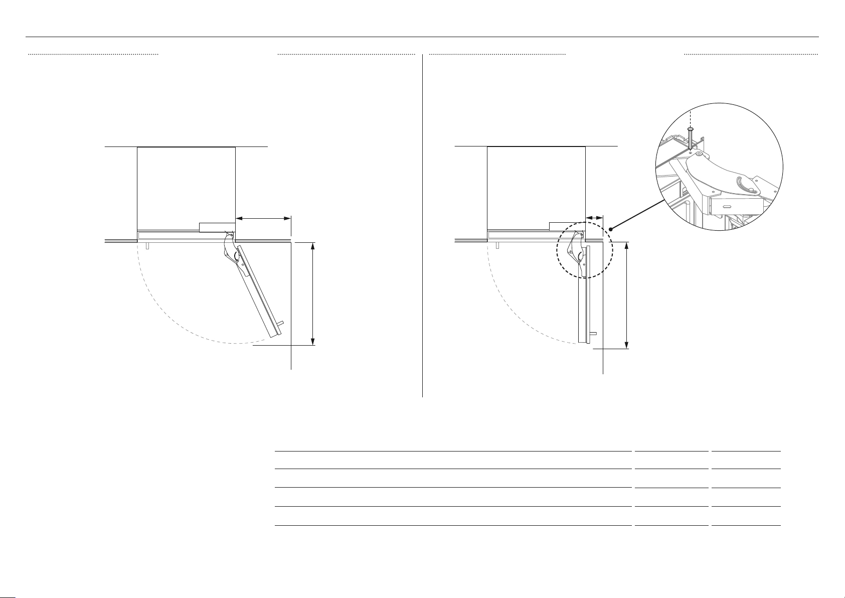
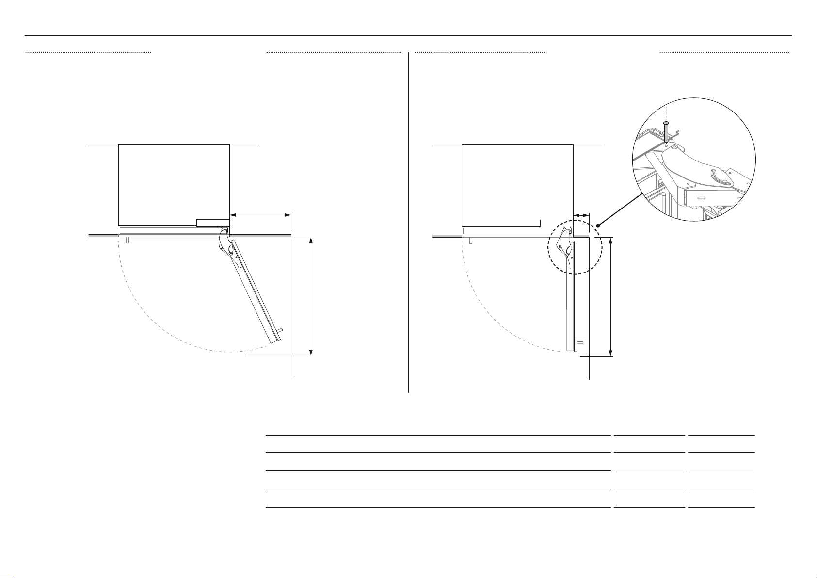
DOOR CLEARANCE — RS24 MODEL
115° DOOR OPENING 90° DOOR OPENING
FULL INTERNAL ACCESS
B
C
Insert hinge limiting pin
Before pushing the appliance into
the cabinetry, insert the supplied
A
A
hinge limiting pin into the borehole
of the top hinge. The hinge limiting
pin limits the door swing to
WALL
LIMITED INTERNAL ACCESS
WALL
DIMENSIONS IN MM
A Width of door (90° open) measured from front of door 26 660
B Minimum door clearance* to adjacent wall** (115°—full internal access) 14 356
90°.
18
C Minimum door clearance* to adjacent wall** (90°—reduced internal access) 4 5/16 110
Page 19
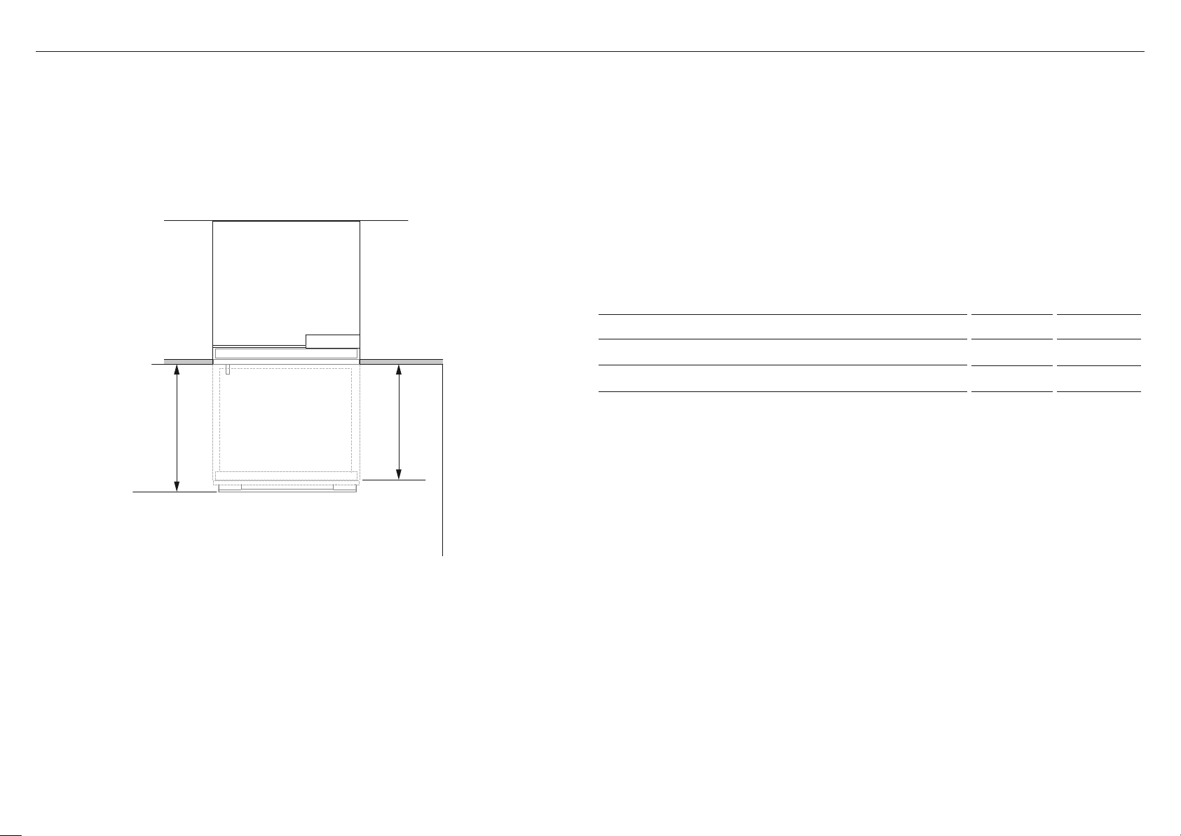
DRAWER CLEARANCE — RS24 MODEL
DIMENSIONS IN MM
A Maximum drawer extension when open (excluding handle) 15 3/4 400
B Maximum drawer extension when open (including handle) 18 1/8 461
B
A
19
Page 20

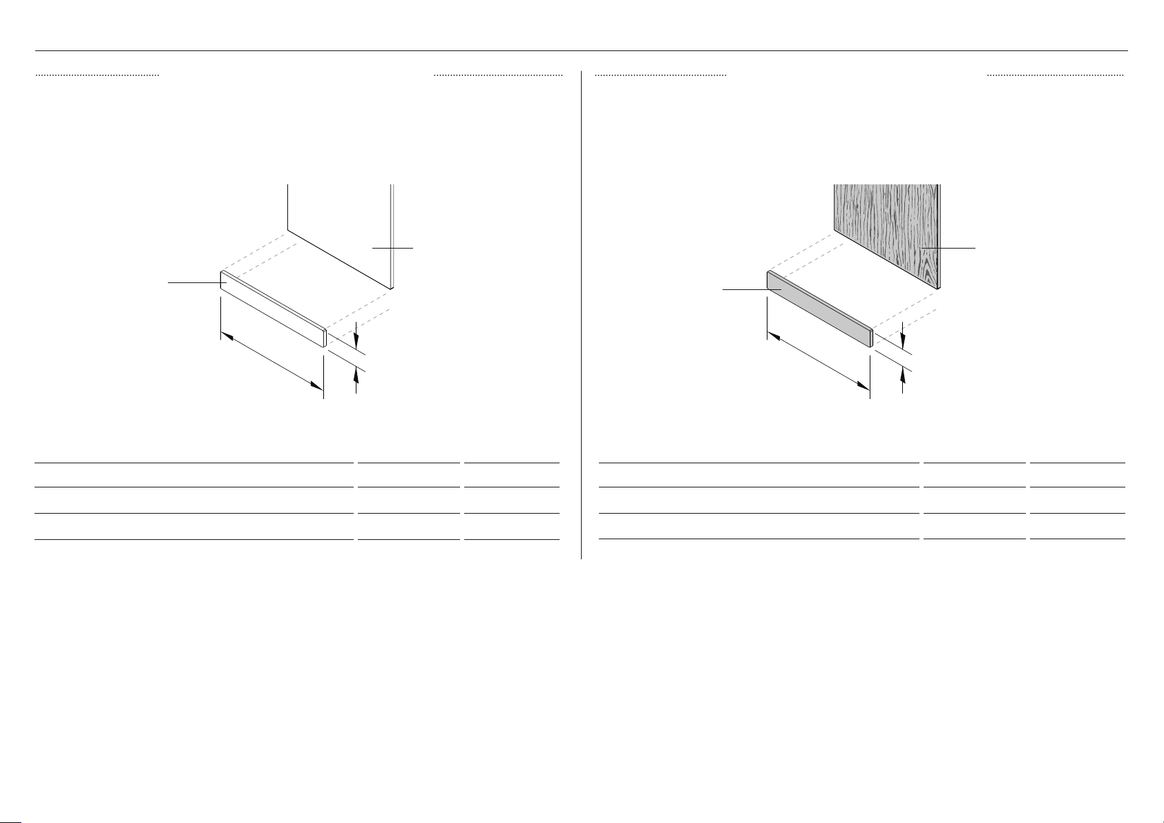
TOE KICK DIMENSIONS — RS24 MODEL
STAINLESS STEEL TOE KICK PANEL CUSTOM PANEL TOE KICK PANEL
Can be purchased separately through an authorised Fisher & Paykel dealer. Visit fisherpaykel.
com for more information.
door panel
toe kick panel
A
TOE KICK PANEL (CA 25390)
DIMENSIONS IN MM
A Width of toe kick 23 7/8 606
B
For Custom door panel installation, a custom toe kick 2” –6” (50 – 152mm) can be
manufactured and fitted by cabinetmaker. The Custom door panel height needs to be adjusted
accordingly. Extra lower grilles are required for a 2” (50mm) toe kick installation.
door panel
toe kick panel
A
DIMENSIONS IN MM
A Width of toe kick 23 7/8 606
B
B Height of toe kick 4 102
20
B Height of toe kick* min 2 - max 6 min 51 - max 152
Page 21

TOE KICK INSTALL OPTIONS
Standard toe kick height is
4" (102mm) with Stainless steel
door panel.
For custom toe kick
with 2" (50mm) height
(extra lower grille attached).
For custom toe kick with 6"
(152mm) height.
Min 27/8" (73mm) – max
4" (102mm) toe kick depth
measured from rearof door
panel
toe kick panel
21
Page 22
PRODUCT DIMENSIONS — RS30 MODEL
A
B
C
PRODUCT DIMENSIONS IN MM
A Overall height of product 84 2134
B Overall width of product 29 3/4 756
C Overall depth of product (excluding front door panel) 24 610
PRODUCT WEIGHT LBS KG
Weight (with packaging) 406 184
Weight (without packaging) 357 162
22
FRONT VIEW
PROFILE VIEW
Page 23
CAVITY DIMENSIONS — RS30 MODEL
FRAMELESS CABINETRY FRAMED CABINETRY
Aligns appliance flush with the cabinetry.
C
A
B
D
A
E
Aligns appliance flush with the frame of cabinetry.
E
C
D
A
B
B
DIMENSIONS IN MM
1 Overall height of cavity
2 Overall width of cavity
3 Minimum overall depth of cavity* 25 635
4 Minimum cabinetry gap clearance from edge of door panels 1/8” 3
5 Minimum required finished return 4” 102
* Assumes a door panel thickness of 3/4” (19mm).
84 2134
30 762
23
Page 24
DOOR PANEL DIMENSIONS — RS30 MODEL
STAINLESS STEEL PANEL CUSTOM PANEL
A
A
B
B
C
DIMENSIONS IN MM
A Height of top door panel 49 3/8 1254
B Height of drawer door panel 30 3/8 772
C Width of door panel 29 3/4 756
D Depth of door panel
(excluding door handle)
DOOR PANEL WEIGHT LBS KG
Weight of top door 22 10
Weight of bottom drawer door 15 7
3/4 19
24
C
DIMENSIONS IN MM
A Height of top door panel 49 3/8 1254
B Height of drawer door panel 30 3/8 772
C Width of door panel 29 3/4 756
D Depth of door panel
(excluding door handle)
DOOR PANEL WEIGHT LBS KG
Weight of top door max 41 max 18 1/2
Weight of bottom drawer door max 25 max 11 1/2
min 5/8
max 1
min 16
max 25
Page 25
CUSTOM DOOR PANEL INSTALL DIMENSIONS — RS30 MODEL
Dimensions apply for the preparation and installation of Custom door panels. For Dwg and Dxf files of the below panel preparation download the folder on thekitchentools.fisherpaykel.com.
z
The thickness of the custom door panel can vary provided that the screws do not penetrate beyond the full depth of the door panel.
z
Measurements of screw hole locations can vary depending on the height of toe kick 50–152mm.
14 7/8" (377.8mm)
8" (203.2mm)
2" (50.8mm)
2" (50mm)
15" (127mm)
20" (507.8mm)
Ø2mm REF
10x Pilot holes recommended
for bracket attachment.
(Do not penetrate front surface).
1 1/2" (38.1m)
3 1/2" (88mm)
14 7/8" (377.8mm)
8" (203.2mm)
2" (50.8mm)
Ø2mm REF
10x Pilot holes recommended
for bracket attachment.
(Do not penetrate front surface).
2" (50mm)
43" (1092mm)
49 3/8" (1254mm)
2" (50mm)
2" (50mm)
29 3/4" (755.6mm)
TOP PANEL—REAR VIEW
Ensure handle is mounted
65mm from edge of panel
to the center—this will avoid
interference with bracket.
1 1/4" (32.6mm)
30 3/8" (771.5mm)
20" (508.4mm)
23 3/16" (588.4mm)
1 1/4" (32.6mm)
Cutouts in the hanging bracket
are applicable for Fisher &
Paykel handles only.
Iflocating a custom handle in
the shaded area shown above,
ensure handle screw headsare
countersunk into the back of the
door panel to avoid interference
with the hanging bracket.
29 3/4" (755.6mm)
BOTTOM PANEL—REAR VIEW
25
Page 26
DOOR CLEARANCE — RS30 MODEL
115° DOOR OPENING 90° DOOR OPENING
FULL INTERNAL ACCESS
B
C
Insert hinge limiting pin
Before pushing the appliance into
the cabinetry, insert the supplied
hinge limiting pin into the borehole
of the top hinge. The hinge limiting
pin limits the door swing to
WALL
A
A
WALL
LIMITED INTERNAL ACCESS
DIMENSIONS IN MM
A Width of door (90° open) measured from front of door 32 813
B Minimum door clearance* to adjacent wall** (115°—full internal access) 16 1/2 419
90°.
26
C Minimum door clearance* to adjacent wall** (90°—reduced internal access) 4 5/16 110
Page 27
DRAWER CLEARANCE — RS30 MODEL
DIMENSIONS IN MM
A Maximum drawer extension when open (excluding handle) 15 3/4 400
B Maximum drawer extension when open (including handle) 18 1/8 461
B
A
27
Page 28
TOE KICK DIMENSIONS — RS30 MODEL
STAINLESS STEEL TOE KICK PANEL CUSTOM PANEL TOE KICK PANEL
Can be purchased separately through an authorised Fisher & Paykel dealer. Visit fisherpaykel.
com for more information.
door panel
toe kick panel
A
TOE KICK PANEL (CA 25392)
DIMENSIONS IN MM
A Width of toe kick 297/8 759
B
For Custom door panel installation, a custom toe kick 2” –6” (50 – 152mm) can be
manufactured and fitted by cabinetmaker. The Custom door panel height needs to be adjusted
accordingly. Extra lower grilles are required for a 2” (50mm) toe kick installation.
door panel
toe kick panel
A
DIMENSIONS IN MM
A Width of toe kick 297/8 759
B
B Height of toe kick 4 102
28
B Height of toe kick* 2-6 51 - 152
Page 29
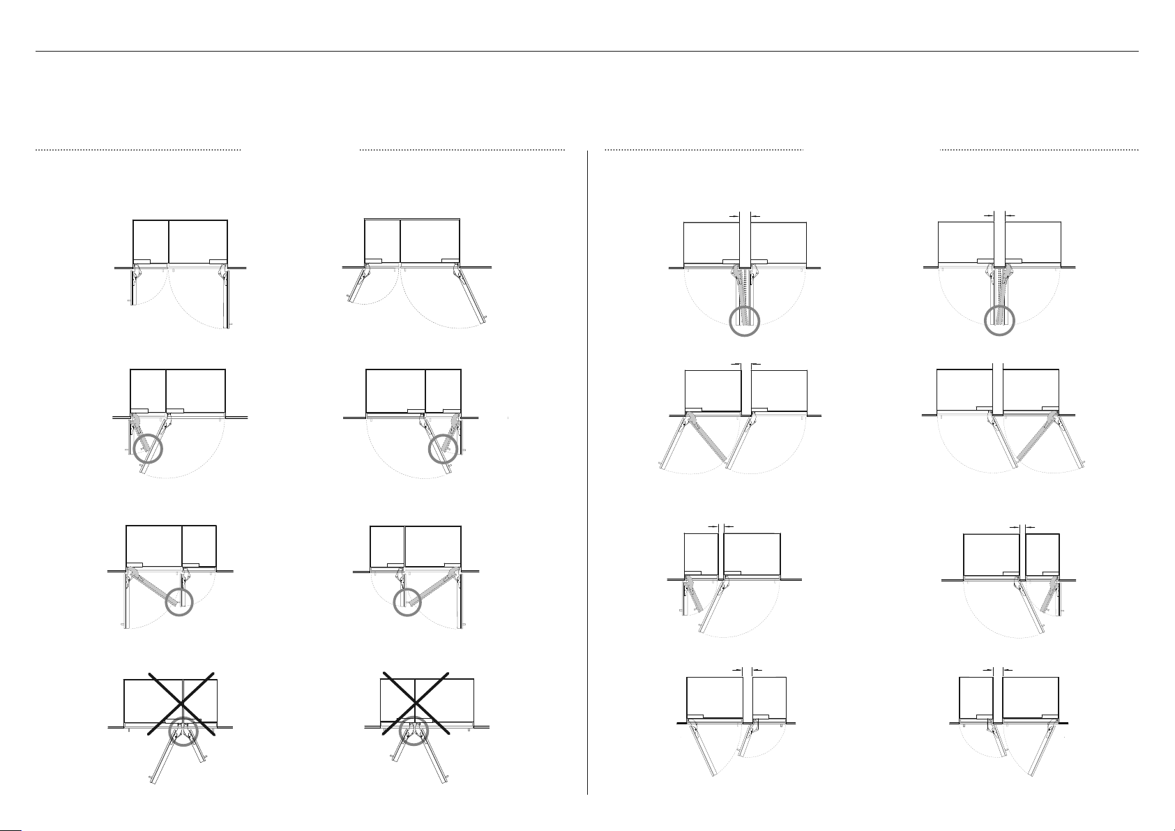
DUAL INSTALL OPTIONS
The following are options for dual/multiple installation with reference to the door opening range and partition (optional) between two appliance combinations.
z
Beware of clashing (circled) when opening the doors. Use a hinge limiting pin to restrict door opening rotation to 90°. Refer to ‘Door Clearance’ for more information.
z
If installing a partition between two appliances, it must have enough clearance to ensure the doors/handles do not interfere with one another when opening or closing.
NO PARTITION WITH PARTITION
min 100mm
min 100mm
min 60mm
min 100mm
min 100mm
min 60mm
min 100mm
min 100mm
29
Page 30
CAVITY DIMENSIONS — RS24 + RS24 DUAL INSTALL
FRAMELESS CABINETRY FRAMED CABINETRY
Aligns appliance flush with the cabinetry.
C
A
B
D
E
Aligns appliance flush with the frame of cabinetry.
E
C
D
A
B
30
DIMENSIONS IN MM
A Overall height of cavity
B Overall width of cavity
C Minimum overall depth of cavity* 25 635
D Minimum cabinetry gap clearance from edge of door panels 1/8” 3
E Minimum required finished return 4” 102
* Assumes a door panel thickness of 3/4” (19mm).
84 2134
48 1219
Page 31

CAVITY DIMENSIONS — RS24 + RS30 DUAL INSTALL
FRAMELESS CABINETRY FRAMED CABINETRY
Aligns appliance flush with the cabinetry.
C
A
B
D
E
Aligns appliance flush with the frame of cabinetry.
E
C
D
A
B
DIMENSIONS IN MM
A Overall height of cavity
B Overall width of cavity
C Minimum overall depth of cavity* 25 635
D Minimum cabinetry gap clearance from edge of door panels 1/8” 3
E Minimum required finished return 4” 102
* Assumes a door panel thickness of 3/4” (19mm).
84 2134
54 1372
31
Page 32
CAVITY DIMENSIONS — RS30 + RS30 DUAL INSTALL
FRAMELESS CABINETRY FRAMED CABINETRY
Aligns appliance flush with the cabinetry.
C
A
B
D
E
Aligns appliance flush with the frame of cabinetry.
E
C
D
A
B
32
DIMENSIONS IN MM
A Overall height of cavity
B Overall width of cavity
C Minimum overall depth of cavity* 25 635
D Minimum cabinetry gap clearance from edge of door panels 1/8” 3
E Minimum required finished return 4” 102
* Assumes a door panel thickness of 3/4” (19mm).
84 2134
60 1524
Page 33

TOE KICK PANEL DIMENSIONS — DUAL INSTALL
STAINLESS STEEL PANEL CUSTOM PANEL
toe kick panel
C
A
B
TOE KICK PANEL (CA 25396) RS24 + RS24 MODELS
DIMENSIONS IN MM
A Width of toe kick 477/8 1216
B Height of toe kick 4 102
TOE KICK PANEL (CA 25398) RS24 + RS30 MODELS
DIMENSIONS IN MM
A Width of toe kick 53 7/8 1368
B Height of toe kick 4 102
door panels
toe kick panel
A
DIMENSIONS IN MM
A Width of toe kick 477/8 1216
B Height of toe kick* min 2 - max 6 min 51 - max 152
DIMENSIONS IN MM
A Width of toe kick 53 7/8 1368
B Height of toe kick* min 2 - max 6 min 51 - max 152
C
door panels
B
RS24 + RS24 MODELS
RS24 + RS30 MODELS
TOE KICK PANEL (CA 25400) RS30 + RS30 MODELS
DIMENSIONS IN MM
A Width of toe kick 59 7/8 1521
B Height of toe kick 4 102
RS30 + RS30 MODELS
DIMENSIONS IN MM
A Width of toe kick 59 7/8 1521
B Height of toe kick* min 2 - max 6 min 51 - max 152
33
Page 34

POWER SUPPLY DIMENSIONS
SINGLE INSTALLATION DUAL INSTALLATION
A
1
2
1
Electrical connection must be within this
space if located behind the appliance and
must not protrude from the back wall.
C
1
2
1
ELECTRICAL AND PLUMBING CONNECTIONS
1 Recommended location for connections in adjacent area or unit
2 Alternative location for connections at rear of cavity
ELECTRICAL DIMENSIONS IN MM
A Overall height of supply area 9 229
B Overall depth of supply area 1" 25
C Width of notch in supply area
(both sides) 1/2 13
34
D
B
D Height of sides of supply area
(both sides) 5127
Page 35

PLUMBING SPECIFICATIONELECTRICAL SPECIFICATION
A
Power cord
b
Power cord
Supply 115 VAC, 60 Hz
Service 10 amp circuit
Socket 3-prong grounding-type
Power cord (total length) 78 3/4" (2000mm)
RS24 RS30
MAXIMUM DISTANCE OF POWER CORD in mm in mm
A Power cord length from left side edge of appliance
(excluding plug)
B Power cord length from right side edge of appliance
(excluding plug)
71 1/4 1809 68 1/4 1733
72 1/4 1835 69 1/4 1759
a
Water hose
b
Water hose
Supply 1/2” (12.7mm) BSP Stainless steel braided hose
withadaptor
Pressure psi (kPa) min 150psi (22) /max 827psi (120kPa) @ 68°F
(20°C)
Water inlet hose (total length) 118 1/8 (3000mm)
RS24 RS30
MAXIMUM DISTANCE OF SUPPLIED WATER HOSE in mm in mm
A Water inlet hose length from left side edge of
appliance
B Water inlet hose length from right side edge of
appliance
86 7/16 2196 83 7/16 2120
73 15/16 1878 70 15/16 1802
35
Page 36

Anti-tip bracket
assembly kit
overhead
cabinetry
INSTALL ANTI-TIP BRACKET
Anti-tip bracket
(1)
Masonry plug
(4)
#10x40 cross-head screw
(4)
Tools
Cross-head screwdriver
Powered drill
Floor
A
back wall
min 7 3/4" (197mm)
bracket
stud
B
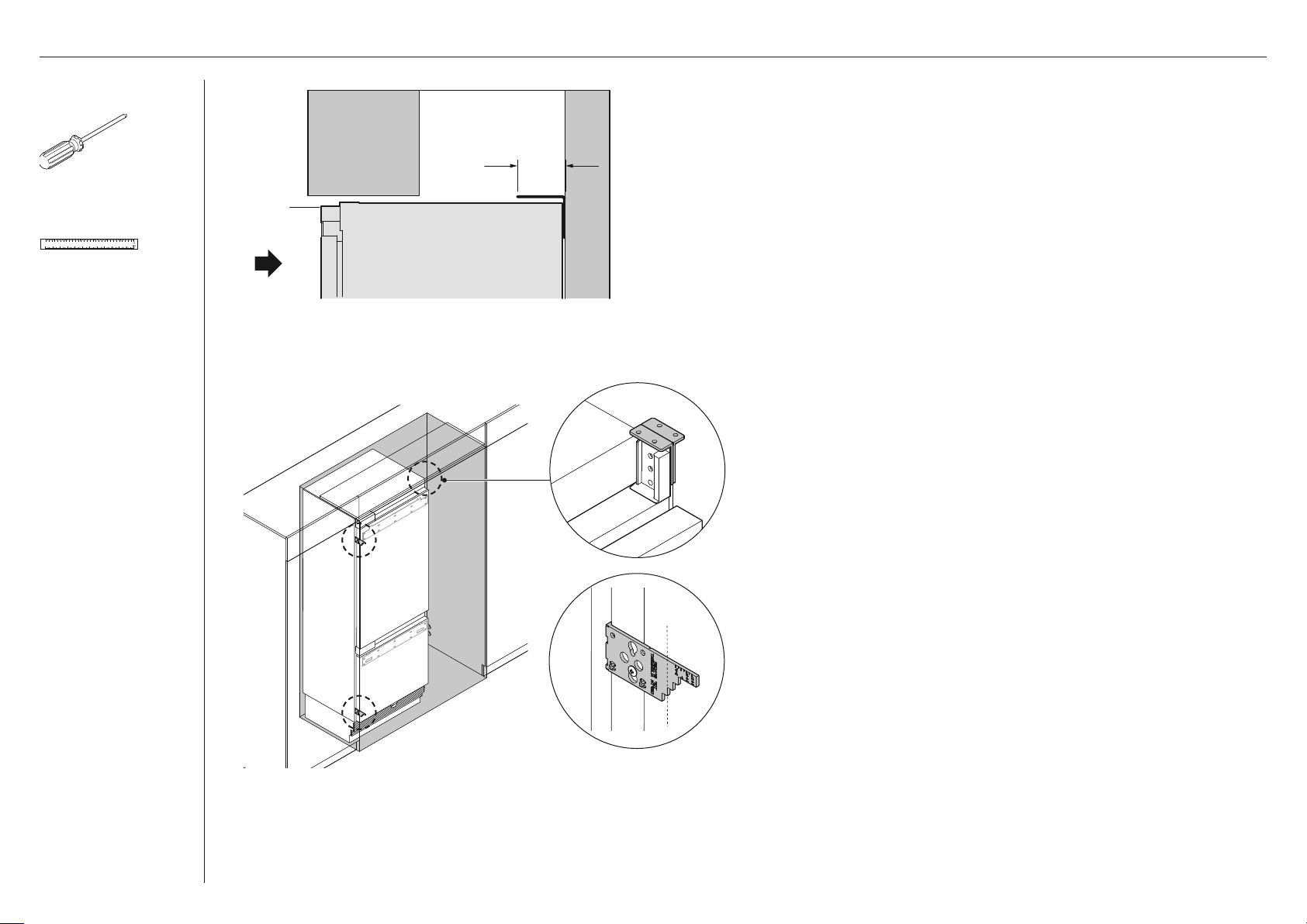
Locating the attachment position of anti-tip bracket
1 Measure the height (A) of the attachment location from
the floor to the alcove return at the back wall, and mark a
horizontal line (B).
z
The height (A) must not exceed 84 3/16" (2138mm) to
ensure the appliance does not tip over during installation.
z
Ensure there is a stud behind the wall.
2 Place the bracket to the backwall. Align the undersurface of
the bracket along the marked line.
Pencil
36
PROFILE VIEW
3 Mark screw hole locations, and drill screw holes with
powered drill.
z
For solid wall installation, drill holes suitable to the size of
the masonry plugs.
Page 37

Anti-tip bracket
assembly kit
INSTALL ANTI-TIP BRACKET
Anti-tip bracket
(1)
Masonry plug
(4)
#10x40 cross-head screw
(4)
Tools
Cross-head screwdriver
Powered drill
screws
masonry plugs
For plaster board wall
Fix the anti-tip bracket to the
wall with #10x40mm cross head
screws, and screw tightly with a
screwdriver.
For solid wall installation
Hammer 10x30mm masonry plugs
into wall until flush. Fix bracket to
wall with #10x40mm cross head
screws, and screw tightly.
min 7 1/16" (180mm)
Bracket
Appliance Wall
PROFILE VIEW
min 7 1/16" (180mm)
Bracket
Appliance
Spacer
Wall
Roll the appliance slowly into
the cabinetry until the anti-tip
bracket overlaps the back edge
of the appliance.
z
Ensure the bracket overlaps
the appliance by a minimum
7 1/16" (180mm) for a secure
hold.
If minimum 7 1/16" (180mm)
overlap cannot be achieved,
install a solid spacer to the wall
stud behind the bracket.
z
Be careful not to run over
the power cord when rolling
in the appliance.
Pencil
PROFILE VIEW
37
Page 38

Water fittings kit
Collet locking clip
(1)
7/16" (11mm) BSP
Stainless steel braided
hose with adaptor
(1)
1/4” (6.35mm) Adaptor
(2)
A
Rear side
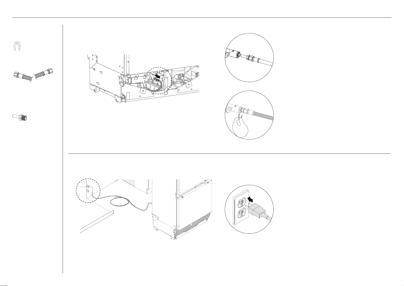
CONNECT WATER AND POWER SUPPLY
Connecting to water supply
1 Roll the appliance to the front of the cabinetry close enough to
allow access at the back for power and water connection.
2 Insert the adaptor end of the braided
hose through a hole at the rear of the
plinth (A) and push all the way to the front of the appliance.
38
B
3 Connect one end of the braided water hose to the water tap (B).
z
Flush water through the hose prior to connection to the appliance
to remove any debris in the hose.
4 Pull the hose from the front of the appliance and connect
an adaptor (C).
C
Page 39
Water fittings kit
CONNECT WATER AND POWER SUPPLY
Collet locking clip
(1)
7/16" (11mm) BSP
Stainless steel braided
hose with adaptor
(1)
1/4” (6mm) Adaptor
(2x)
C
D
5 Insert the tube end of the adaptor fully into the
PLV (C) at the bottom front of the appliance.
6 Secure the connection with a locking clip
between the PLV and hose end of adaptor (D).
z
Check the connection and open the water
supply to testfor leaks.
E
Connecting to power supply
1 At the back of your appliance, connect the power
cable to the power supply (115VAC, 60Hz) (E).
z
You will hear a chime sound when the
appliance is powered on.
z
Refer to your ‘User guide’ for more details on
activating the appliance.
39
Page 40

Install fasteners kit
POSITION AND ALIGNMENT IN CABINETRY
Barbed plugs
(2)
Barbed plug
A
B
Attaching the barbed plugs
1 Before rolling into the cavity, insert a barbed
plug into a large hole at the top left side (A)
of the appliance.
z
The plugs protect the inside surface of
cabinetry from being damaged by screws
when pushing in the appliance.
Repeat steps
1 — 2 to the right side (B) of the
appliance.
40
Page 41

Install fasteners kit
Cabinet depth
alignment gauge
(4)
Tools
Cross-head screwdriver
POSITION AND ALIGNMENT IN CABINETRY
Attaching the depth alignment gauges
1 Loosen the right and left screws at the top and bottom
sides of the door. (A)
2 Locate the alignment gauges at correct orientation to the
right and left screws.
A
C
B
Left
3 Position the alignment gauge by inserting the screw head
through the keyhole of the gauge. (B)
4 Push the alignment gauge down to lock the screw position
in the keyhole. (C)
5 Tighten the screw just enough to firmly hold the gauge.
The alignment gauges are only temporary and must be
removed after installation.
Right
41
Page 42

POSITION AND ALIGNMENT IN CABINETRY
min 7 1/16" (180mm)
Bracket
PROFILE VIEW
Positioning into the cabinetry
1 Roll the appliance slowly into the cabinetry until the
anti-tip bracket overlaps the back edge of the appliance.
Ensure the bracket overlaps the appliance by a minimum
7 1/16" (180mm) for a secure hold.
Be careful not to run over the water hose and power cord when
rolling in the appliance.
42
Page 43

Tools
Cross-head screwdriver
Ruler
POSITION AND ALIGNMENT IN CABINETRY
Aligning with the depth gauges
1 Mark the step of the depth gauges (A, B) on both sides of
the door based on the thickness of door panel.
z
Example illustrations showing 1" (25.4mm) door panel
thickness marked on the gauges.
Pencil
A
Left
C
B
Right
2 Check if the gaps between appliance and cabinetry side walls are
even on left and right sides (C, D).
D
C
C
D
D
Left
Right
43
Page 44

Tools
Cross-head screwdriver
Powered driver
(optional)
POSITION AND ALIGNMENT IN CABINETRY
Adjusting the alignment in the cabinetry
z
Clockwise turn of the front and rear adjustment screws
Front foot
A
A
adjustment
screw
Rear foot
adjustment
screw
Foot
(A) raise the height of the appliance.
z
Counter-clockwise turn of the adjustment screws lower
the height of the appliance.
1 Turn the front and rear adjustment screws clockwise
to extend the front feet (B) and rear feet (C) until
they engage the floor and the top bracket reaches the
cabinetry ceiling.
44
b
Front side view Rear side view
D
c
2 Check the depth gauges (D) while adjusting the
screws to maintain alignment of the appliance.
Page 45

Install fasteners kit
8Gx16 Countersunk
screw (6)
Tools
SECURE APPLIANCE TO CABINETRY
Securing the top brackets
Fix the top brackets to the ceiling surface of the
cabinetry with 8Gx16 countersunk screws. (A)
Cross-head screwdriver
Powered driver
(optional)
AA
Securing the side brackets
bb
Fix the side brackets (2x) to the lower right and left sides
of the cabinetry with 8Gx16 countersunk screws. (B)
Once the appliance is secured to the cabinetry, remove
the alignment gauges and re-tighten the side screws.
45
Page 46
Tools
Powered driver
M8 hex key
(1)
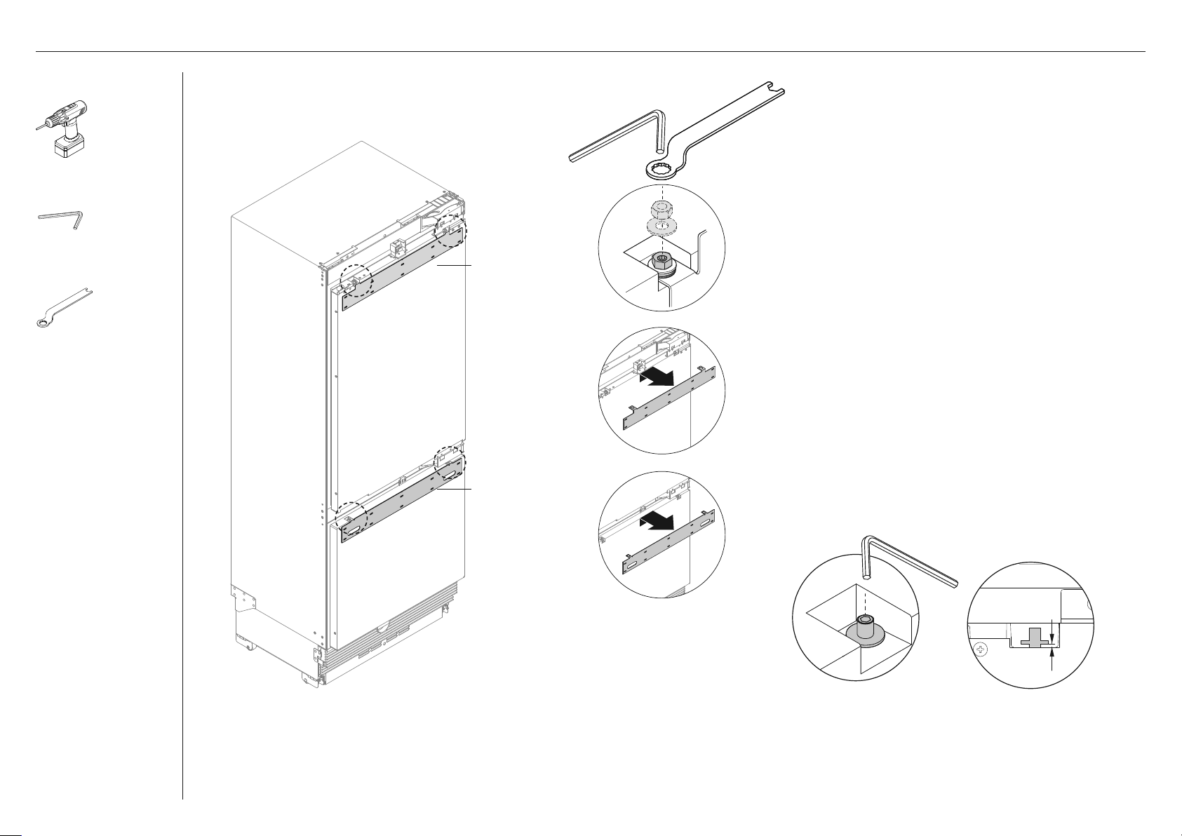
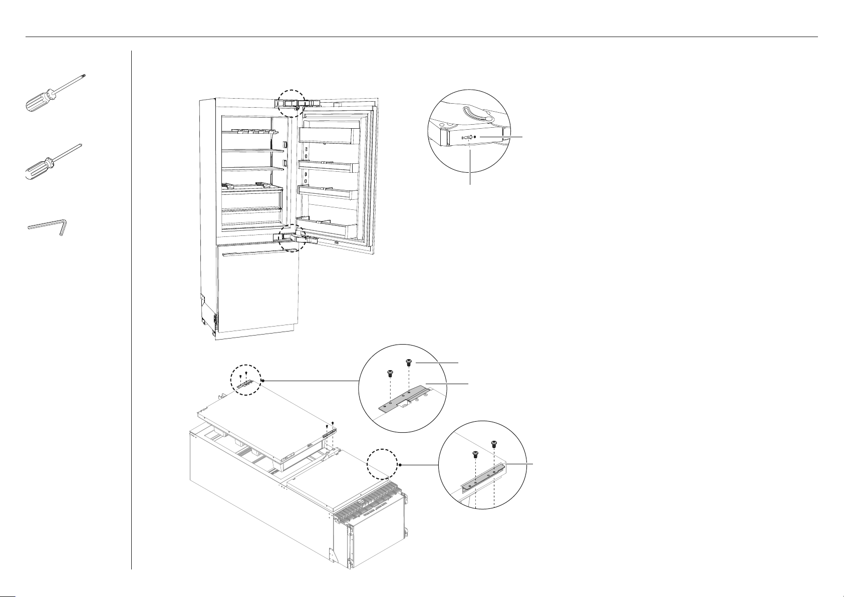
REMOVE HANGING BRACKETS
a
b
top hanging bracket
1 Remove the M8 nut (A) and M8 washer (B) from the
M8 screw at the top of the refrigerator door using the
supplied hex key and spanner.
z
Repeat for the top of the drawer door.
13mm spanner (1)
2 Remove the top and bottom hanging brackets (D, E) and
set aside to use later.
d
bottom hanging bracket
3 Loosen the M8 screw (C) by 1/8" (3mm).
e
c
46
Page 47

INSTALL DOOR AND DRAWER PANELS
Door handle kit
M5x25 Hex screw
(4x)
Tools
Powered driver
M8 hex key
(1)
13mm spanner (1)
STAINLESS STEEL PANELS CUSTOM PANELS
Remove the protective film around the handle attachment area of the
stainless steel panel before installing the handle.
Attaching refrigerator door handle
1 Secure the door handle to the handle
holes of the refrigerator door with
M5x25 pan head socket screws. (A)
A
blue tape
A
Attaching refrigerator door handle
1 Refer to 'Custom door panel
dimensions' page to locate the screw
holes on the door panel.
2 Secure the top door handle to the
handle holes of the refrigerator door
with #8x16 mush washer screw. (A)
B
Attaching freezer drawer handle
2 Secure the door handle to the
handle holes of the freezer door with
M5x25 pan head socket screws. (B)
blue tape
Remove the blue tape attached to inner edges of the door panels after the
handles are installed.
B
Attaching freezer drawer handle
3 Secure the bottom door handle to the
handle holes of the freezer door with
#8x16 mush washer screw. (B)
Ensure the door and drawer handles do not interfere when attaching the
side attachment brackets. Refer to 'Custom door panel install dimensions'
(page 17, page 25).
47
Page 48

INSTALL DOOR AND DRAWER PANELS
Door panel
attachment kit
Side bracket
(6)
Bracket slider
(6)
Bracket spacer
(6)
8Gx16 Mush washer
screw (30) — For
Stainless steel panels
M5x12 Cross-head screw
(30) — For Custom
panels
Tools
Powered driver
c
c
c
STAINLESS STEEL PANELS
Attaching top hanging
bracket
1 Secure the top hanging
Attaching side brackets
2 Secure the bracket
Attaching bottom hanging
bracket
3 Secure the bottom
B
B
B
A
A
B
c
d
d
bracket (A) to the screw
holes of the refrigerator
door panel with 8Gx16
Mush washer screws.
spacer, side bracket
and bracket slider (in
order as per drawing)
to the screw holes on
both sides of the door
and drawer panels
with 8Gx16 mush
washer screws. (B)
hanging bracket (D)
to the screw holes
of the freezer door
panels with 8Gx16 Mush
washer screws.
D
D
D
custom door panel
A
CUSTOM PANELS
B
C
C
C
A
C
D
hanging bracket
Attaching top hanging
bracket
1 Mark a line across
the center of the
custom door panel.
2 Align the top of the
centerline to the ‘V’
notch in the bracket. (A)
3 Secure the top hanging
B
bracket (B) to the screw
holes of the refrigerator
custom door panel with
M5x12 cross-head screws
Attaching side brackets
4 Secure the bracket
spacer, side bracket
and bracket slider (in
order as per drawing)
to the screw holes on
both sides of the door
and drawer panels
with M5x12 crosshead screw. (C).
48
Attaching bottom hanging
bracket
5 Secure the bottom
D
hanging bracket to
the screw holes of the
freezer door panels
with M5x12 Crosshead screws. (C)
Page 49

Tools
Powered driver
(with 2.5mm drill bit)
INSTALL DOOR AND DRAWER PANELS
A
b
Hanging the refrigerator door panel
1 Hold the door panel at an angle towards the top of
the refrigerator door (A).
Cross-head screwdriver
M4 hex key
(1)
1/2" (13mm) spanner
(1)
A
c
adjustment
screw
c
c
b
c
Left isometric view
hanging
bracket
D
2 Lower the screw holes of the hanging bracket
onto the adjustment screws at the top of the
refrigerator door. (B)
3 Screw the M8 washer and nut to the adjustment
screw and loosely tighten.
4 Slide-in the side brackets (C) to the side screws
of the door, and align the door panel straight
with the refrigerator door.
5 Tighten the side screws (D) loosely to
temporarily secure the door panel.
door panel
c
Repeat steps 1 - 4 for the freezer drawer panel.
49
Page 50

INSTALL DOOR AND DRAWER PANELS
Tools
Cross-head
screwdriver
M4 hex key
(1)
13mm spanner
(1)
Ensure the side brackets are loosely screwed when adjusting the height of the
door panel. Do not adjust the door panel height when the side brackets are
screwed tight. This can generate friction which causes the hanging brackets to
bend.
Adjusting height of door panel
1 Turn the adjustment screw to raise
or lower the height of the door panel
relative to the door.
2 Continue adjustment until gap with
Lower
Raise
cabinetry is more than 1/8 (3mm).
Do not adjust the adjustment screw
higher than 1/4" (6.5mm) from its fully
down position.
To adjust door panel further, remove the
door panel then loosen the fixing screws
of the hanging bracket and move the
bracket sideways to suit.
50
Adjusting depth of door panel
3 Loosen side screws on the side
brackets, and slide door panel
forward/backward.
4 Re-tighten once satisfied.
To adjust door panel further, remove the
door panel then loosen the fixing screws
of the hanging bracket and move the
bracket sideways to suit.
z
Once satisfied with door panel position,
fully tighten M8 washer and nut to
adjustment screw.
Page 51

Tools
Cross-head
screwdriver
Cutter
M4 hex key
(1)
INSTALL LOCKING BRACKET
INSTALL ADJUSTMENT BRACKETS
13mm spanner
(1)
B
A
1 Loosen the screw at the bottom
of the refrigerator door, and slide
thelocking bracket (A) out until it
touches the panel.
2 Fix the locking bracket
to the door panel with
8Gx16 countersunk screw (B).
3 Re-tighten the screw at the
bottom of the door.
C
D
1 Loosen the cap screws (C) of the
adjustment brackets (D) on both
sides of the plinth with a hex key.
2 Adjust the brackets to the
desired depth by moving it
forward/backward.
3 Re-tighten the cap screws
once satisfied.
51
Page 52
Miscellaneous
components
INSTALL TOE KICK PANEL
Air toe kick seal
(1)
Toe kick install kit
Toe kick panel
(1)
Tools
Cross-head screwdriver
M4 hex key
(1)
C
a
b
C
b
b
C
a
Attaching the mounting plate
1 Re-attach the toe kick mounting plate (A) to the plinth using same
screws that were set aside previously.
2 If toe kick depth is less than 3 5/8" (92mm), attach an air toe kick
seal (B) to the mounting plate.
z
Peel off the adhesive tape of air toe kick seal and attach to the
middle of the back side of the mounting plate.
3 Peel off the adhesive tape backing of the magnets (C) attached to
the mounting plate.
52
D
toe kick
D
D
Attaching the toe kick panel
1 Position the toe kick in front of the mounting plate.
z
The spacers (D) on the toe kick must be aligned with the
magnets of the mounting plate.
2 Press the toe kick onto the mounting plate to fix the position.
z
For custom toe kick, spacers are not needed.
z
For correct dimensions of toe kick, refer to 'Toe kick panel
dimensions' for more information.
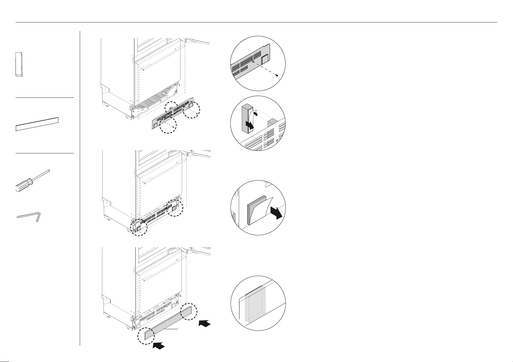
Page 53

Tools
INSTALL TOP TRIMINSTALL TOE KICK GRILLES
Cutter
Cross-head screwdriver
A
b
Installing the top grille
1 Reattach the top grille (A)
using the same screws set
aside previously.
Installing the bottom grille
1 Reattach the bottom grille
(B) to the mounting plate .
z
For toe kick heights
4 1/2" - 5" (114–127mm),
shorten the bottom grille by
cutting along the vertical ribs.
a
Reinstalling the top trim
1 Slide one end of the top trim
(A) into the hinge pocket
of the appliance.
2 Press the other end to engage the
dual lock strips on the non-hinge
side of the appliance.
Toe kick, top and bottom
grilles complete installation
53
Page 54

Supplied tools
INSTALL WATER FILTER
Water filter
(1)
filter removal tool
top grille
Inserting the water filter
1 Remove the packaging from
the water filter.
2 Align the filter head with the
slot of the filter removal tool
and push until it clips in place.
3 Using the water removal tool,
hold the water filter with the
handle positioned vertically
and insert into the filter casing
through a hole in the top grille.
Removing and replacing the filter
1 To remove the water filter,
turn the filter removal tool
counterclockwise and pull
out the filter.
2 Unclip the tool from the
filter head and discard the
used water filter.
Refer to 'Inserting the water filter'
when replacing the filter.
54
4 Push firmly until the water filter
is all the way into the casing.
5 Turn the filter removal tool
clockwise to lock the water
filter in place.
Page 55

INSTALL AIR FLOW DIVIDER
Miscellaneous
components
Flow divider cap
(1)
Tools
Hacksaw
The air flow divider blocks the air flow from bypassing the front of the bottom grille.
B
B
a
1 Remove the adhesive layer (A) off the air flow divider.
2 Reinstall the air flow divider (B) to the bottom of the
freezer drawer with screw.
z
Ensure the adhesive layer side of the divider
contacts the door panel.
3 Press the flow divider firmly against the door panel.
C
4 Attach a flow divider cap (C) to the flow divider.
C
55
Page 56

INSTALL CABINET SIDE TRIMS
Install parts
Cabinet side trim
(2)
Tools
Cross-head screwdriver
Cutter
Dual adhesive strips are pre-attached at four locations along the side trim.
1 Peel off the liners from the
dual adhesive strips (A).
A
2 Position the trim (B) at an
angle on the throat of the
door hinge (C).
b
c
F
e
d
3 Hold the same angle and
slide the side trim bottom
end behind the lower
hinge down to the bottom
drawer side. (D)
4
Slide the side trim top end
behind the top hinge.
e
5 Slot the side trim behind
the top hinge pocket. (E)
6 Press the adhesive strip to
the cavity to ensure the
trim is also tight against the
inner face of the appliance.
7 On the non-hinge side,
slide in the side trim behind
the top trim. (F)
56
F
Page 57

Trims install kit
INSTALL DOOR AND DRAWER SIDE TRIMS
Top door panel side
extrusion (2)
Bottom drawer panel
side extrusion (2)
Bottom drawer top trim
(1)
A
front of door
c
e
b
D
Install door top extrusion
1 Align the top extrusion (A)
to the top of the door, and
match the notch (B) with the
magnet housing (C).
2 Clip the trim caps (D) at both
ends of top extrusion to both
ends of the top of the door.
3 Press the top extrusion down
to the door top surface. (E)
H
G
H
side trim
Install drawer top and side trims
1 Remove the adhesive
backing of adhesive strips
pre-attached to the underside
of the top trim (G).
2 Press down the top trim firmly
to engage the back surface of
the drawer panel.
z
Ensure the trim is fully seated
against the drawer top
surface.
3 Install the side trims (H) by
inserting into the panel gaps
on each side of the door.
z
Ensure the cabinet is
centered to prevent the
side trims from interfering
withthecabinet.
Cabinet side trim
(2)
f
Install door side extrusions
1 Press the side trims (F) to fit
into the panel gaps on the right
and left sides of the door.
2 Align the top of the side trims
to fit with the right and left
ends of the top extrusion.
side view
Your columns Installation is now complete!
57
Page 58

DUAL INSTALLATION
Install fasteners kit
Cabinet depth alignment
gauges (4)
Top joiner
bracket kit
Central spacer
(1)
8Gx16 Mush washer
screw (2)
Tools
Attach central spacer to cabinetry
A
b
1 Measure the widths from the left (A) and right (B) cabinetry
sides towards thecentre to determine the spacer location.
Refer to "Cavity dimensions' page for correct width of the
appliance.
2 Mark the attachment location of the central spacer on the
cabinetry ceiling using the depth alignment gauge (C).
z
The depth position of spacer depends on the door panel
thickness.
Cross-head screwdriver
Powered driver (optional)
58
C
3 Fix a central spacer (C) to the alcove ceiling with
two 8Gx16 countersunk screws.
4 Tightenthescrews with a screwdriver or powered driver.
Page 59

Install fasteners kit
Cabinet depth alignment
gauges (4)
Barbed plugs
(2)
DUAL INSTALLATION
A
Attaching the depth alignment gauges
1 Loosen the screws (A) at the cabinetry sides of the door
and drawer of each appliance.
2 Locate the alignment gauges (B) at correct orientation to
the right and left side screws.
Tools
Cross-head screwdriver
Powered driver (optional)
C
b
Left
3 Position the alignment gauge by inserting the screw head
through the keyhole of the gauge.
4 Push the alignment gauge down to lock the screw position
in the keyhole.
5 Tighten the screw just enough to firmly hold the gauge.
The alignment gauges are only temporary and must be
removed after installation.
Attaching the barbed plugs
1 Before rolling into the cavity, insert barbed plugs
(C) into large holes on the top right and left sides of
both appliances.
Right
2 The plugs protect the inside surface of cabinetry from
being damaged by screws when pushing in the appliance.
59
Page 60
Tools
Cross-head screwdriver
Ruler
A
min 7 1/16" (180mm)
PROFILE VIEW
b
DUAL INSTALLATION
D
Aligning the first appliance into the cabinetry
1 Roll the first appliance (A) slowly into one side of the cabinetry
until the anti-tip bracket (B) overlaps the back edge of
the appliance.
z
Ensure the bracket overlaps the appliance by a
minimum 7 1/16" (180mm) for a secure hold. Refer to
'Install anti-tip bracket' for more information.
60
e
e
C
e
2 Align the top cap (C) of the first appliance flush with the front
of the spacer (D).
F
3 Mark the step of the depth gauges (E) on the cabinetry side of
the door based on the thickness of door panel.
4 Align the marked line (F) flush with the front surface of the
adjacent cabinetry.
Page 61

Install fasteners
kit
8Gx16 Countersunk
screw (6)
Tools
Cross-head
screwdriver
Powered driver
(optional)
Front foot
adjustment
screw
Rear foot
Rear foot
adjustment
screw
Foot
DUAL INSTALLATION
Adjusting the height of first
appliance in cabinetry
1 Turn the front and rear
adjustment screws clockwise
to raise height of the appliance
and counter-clockwise to
lower the height.
2 Turn the front and rear
adjustment screws clockwise to
extend the feet until it engages
the floor, and the top bracket
reaches ceiling of the alcove.
bA
bA
Securing first appliance in
cabinetry
1 Fix the left and right top
brackets (A, B) to the ceiling
surface of the cabinetry with
8Gx16 countersunk screws.
c
D
2 Fix the left and right lower
side brackets (C, D) to the
cabinetry side surface with
8Gx16 countersunk screws.
Ruler
ruler
Front foot
cd
3 Check the alignment gauges
while adjusting the screws
to maintain the alignment
of the appliance.
4 Using a ruler, check if the
gaps between appliance and
cabinetry side wall are even.
61
Page 62

Tools
Cross-head screwdriver
Ruler
A
PROFILE VIEW
min 180mm
b
DUAL INSTALLATION
D
C
E
Aligning the second appliance into the cabinetry
1 Push the second appliance (A) to roll slowly into
the other side of the cabinetry side by side with the
first appliance.
z
Ensure the bracket (B) overlaps the appliance
by a minimum 180mm for a secure hold. Refer to
'Install anti-tip bracket' for more information.
2 Align the top cap (C) of the second appliance flush
with the central spacer (D) and top cap (E) of the
first appliance.
62
H
G
F
adjacent cabinetry
3 Mark the step of depth gauge (F) on the
cabinetry side of the door based on the thickness
of door panel.
4 Align the marked line (G) flush with the front
surface of the adjacent cabinetry.
5 Adjust the height of the second appliance.
Refer to 'Adjusting the height of first appliance in
cabinetry' (page 59).
6 Using a ruler (H), check if the gaps between
appliances and cabinetry side walls are even.
Page 63

Top joiner fastener kit
DUAL INSTALLATION
M5x20 Cap
screw (1)
M5x16x1 Plain washer
(1)
Bottom joiner
fastener kit
M6x16 Washer screw
(1)
M6x12x3.2 Plastic washer
(1)
M6 Hex nut
(1)
D
BA
Securing the top brackets
1 Secure the top caps of both appliances to the central
spacer with M5x20 cap screw (A) and washer (B).
2 Secure the top brackets to the ceiling surface of the
cabinetry with 8Gx16 countersunk screws. (C)
c
Securing the bottom brackets
3 Secure the bottom joiner brackets of both
appliances together with the bottom joiner
fastener kit (D).
8Gx16 Countersunk screw
(5)
Tools
M4 Hex key
Cross-head screwdriver
D
E F
E
F
4 Secure the left and right bottom side brackets (E, F)
of the second appliance to the cabinetry with 8Gx16
countersunk screw.
Refer to the following pages to complete your
installation (pages 44-55):
z
Remove hanging brackets
z
Install door and drawer panels
z
Install locking bracket
z
Install adjustment brackets
z
Install toe kick panel
z
Install toe kick grilles
z
Install top trim
z
Install water filter
z
Install air flow divider
z
Install cabinet side trims
z
Install door and drawer side trims
63
Page 64
CHANGE THE DOOR HINGES (OPTIONAL)
Tools
T2 star-head screwdriver
Cross-head screwdriver
Hex key
You have the option to switch the door hinge side of your appliance from right hand hinge to left hand hinge or vice versa. A hinge change kit is required for this
installation, and must be purchased separately.
‘0’
T20 screw
Ensure that you remove all the shelves, covers
and trims from the appliance before changing the
hinges. Take care not to damage the door.
1 Release the hinge spring by turning the T20
screw in the hinge to the ‘0’ position.
2 Do this to both top and middle hinges.
64
M6x10 hex screws
Top hinge
Bottom hinge
3 Close the door and place the appliance on its
back on the pallet.
4 Detach the door from the appliance by
unscrewing the door hinge M6x10 hex screws at
the top and middle hinges.
Page 65

Tools
CHANGE THE DOOR HINGES (OPTIONAL)
A
T2 star-head screwdriver
Flat-head screwdriver
Removing the top door hinge
b
C
1 Rotate the top hinge (A) outwards and remove the top
hinge pocket cover (B) using the flat head screwdriver in
the slot of the cover.
E
D
f
2 Unscrew M6x16 countersunk screws (C) to remove top
hinge, and set aside to use later.
3 Unscrew M6x16 countersunk screws (D) from hinge pocket
to remove hinge pocket and top alcove bracket.
4 Unscrew M5x12 countersunk screws (E) to remove top hinge
bracket and spacer.
5 For the non-hinge side, remove the top alcove bracket by
unscrewing the M6x16 countersunk screws (F).
G
Removing the middle door hinge
1 Rotate the middle hinge (G) and unscrew M6x16
H
countersunk screws (H) to remove middle hinge, and set
aside to use later.
2 Unscrew M5x12 countersunk screws (I) to remove top hinge
I
bracket and spacer.
65
Page 66

CHANGE THE DOOR HINGES (OPTIONAL)
Tools
T20 star-head
screwdriver
Flat-head
screwdriver
Moving the sensor housing
1 Unclip the hall sensor
from the housing.
2 Unhook the
interceptor board
harness from
sensor housing so
harness is loose.
4 Move the sensor
housing to align the
opposite hall sensor
clip with the centre
of the cabinet.
5 Reinstall the sensor
housing using #8x16
screws (2x) into the
pre-drilled holes in
the cabinet top panel.
6 Clip the hall sensor
into the sensor housing
in the pocket closest
F
to the centreline
of the cabinet.
66
3 Remove the #8x16
screws (2x) from the
sensor housing.
7 Press the harness from
the interceptor board
into the forks on the
sensor housing.
Page 67

Hinge change
assembly
Hinge (right or left) top
pocket (1)
Lower (right or left)
hinge bracket (1)
K05 top adapter bracket
(1)
Top grille assembly
CHANGE THE DOOR HINGES (OPTIONAL)
D
Reinstalling the top hinge
c
A
e
b
f
1 Reinstall the hinge top bracket and bracket spacer
with M5x12 countersunk screws (A) onthe new hinge
side at the other side of theappliance.
2 Install the new hinge pocket and alcove top bracket
on the new hinge side using two (2x) M6x16
countersunk screws (B).
z
The new hinge pocket and top alcove bracket are
supplied with the hinge kit.
3 Install the new hinge in the new hinge pocket by
screwing M6x16 countersunk screws (2x) (C).
4 Open the hinge (D) and reinstall the top hinge pocket
cover (E) to the top hinge pocket..
5 Install a new top alcove bracket on the new
non-hinge side (F).
Top (fixed) grille
(1)
H
I
Reinstalling the middle door hinge
1 Reinstall the middle hinge bracket and spacer with M5x12
countersunk screws (G).
G
2 Open the middle hinge (H) and reinstall the hinge with
M6x16 countersunk screws (I).
67
Page 68

Hinge change
assembly
K05 top adaptor
bracket R/L (1)
K05 bottom adaptor
bracket R/L (1)
Tools
T2 star-head screwdriver
CHANGE THE DOOR HINGES (OPTIONAL)
A
use new top
adaptor bracket
b
Changing the top door bracket
1 Unscrew the M5x10 screws (4x) to remove the top
adapter bracket from the top of the door (A).
2 Install the new top adapter bracket into the
other side of thetop of the door with M5x10
screws (4x) (B).
Flat-head screwdriver
68
c
d
use new bottom adaptor
bracket and spacer
e
f
use existing locking bracket
Changing the bottom door bracket
1 Remove the door panel locking bracket and
washer from thebottom of the door by
unscrewing M6x25 screw (1x) (C).
2 Remove the bottom adapter bracket and spacer
from the bottom of the door by unscrewing M6x25
screws (2x) andM5x30 screw (1x) (D).
3 Install the new bottom adapter bracket and
existing spacer to the other side of the door with
M6x25 screws (2x) and M5x30 screw (1x) (E).
4 Install the existing door panel locking bracket and
washer tothe other side of the door with M6x25
screw (1x) (F).
Page 69

Tools
T2 star-head screwdriver
Flat-head screwdriver
Hex key
CHANGE THE DOOR HINGES (OPTIONAL)
A
Reinstalling the door
1 Secure the door to the top and middle hinges of
the appliance using M6x10 hex screws (4x). (A)
A
2 Activate the hinge spring by turning the star T20
screws to the I position. (B)
B
3 Return the appliance to the upright position, and
reinstall all covers and trims.
69
Page 70

TO BE COMPLETED BY THE INSTALLER
All models
F Check all parts are installed.
F Ensure the appliance is level.
F Ensure the appliance is securely fastened to the cabinetry with the
supplied anti-tip bracket and fittings.
F Ensure the door can open and close freely with no resistance from
surroundingcabinetry.
F Ensure hinge limiting pin is fitted for 90° door swing.
F Ensure all internal and external packaging is removed from the appliance
before use.
F Ensure that you write down and keep the wifi password, serial and model
numbers of your appliance.
FINAL CHECKLIST
Complete and keep for safe reference:
Model _____________________________________________________________
Serial No. _____________________________________________________________
Purchase Date _____________________________________________________________
Purchaser _____________________________________________________________
Dealer Address _____________________________________________________________
Installer’s Name _____________________________________________________________
Installer’s Signature _____________________________________________________________
Installation Company _____________________________________________________________
Installation Date _____________________________________________________________
70
Page 71

Page 72

FISHERPAYKEL.COM
© Fisher & Paykel Appliances 2020. All rights reserved.
The appliance specifications in this document apply to the specific
appliances and models described at the date of issue. Under our policy
of continuous appliance improvement, these specifications may change
at any time. You should therefore check with your Dealer to ensure this
document correctly describes the appliance currently available.
US CA
86026B0.20
Page 73

COLONNE ENCASTRABLE
RÉFRIGÉRATEUR CONGÉLATEUR
Modèles RS2484WR, RS2484WL, RS3084WR
et RS3084WL
GUIDE D’INSTALLATION
US CA
86026B0.20
Page 74

Page 75

TABLE DES MATIÈRES
Consignes de sécurité et mises en garde 4
Colonnes encastrables — réfrigérateur–congélateur 5
Vérification de votre appareil 6
Déplacement de votre appareil 7
Avant l’installation 8
Pièces fournies 9
Pièces requises 11
panneau de plinthe 11
Ensemble de panneau de porte 12
Ensembles de poignée de porte et tiroir 12
Ensemble de changement de côté des charnières 13
Dimensions du produit— MODÈLE RS24 14
Dimensions de la cavité — Modèle RS24 15
Dimensions de panneau de porte— MODÈLE RS24 16
Dimensions d’installation de panneau de porte sur mesure— MODÈLE RS24 17
Dégagement de la porte — modèle RS24 18
Dégagement du tiroir — modèle RS24 19
Dimensions de la plinthe — modèle RS24 20
Options d’installation de la plinthe 21
Dimensions du produit— modèle RS30 22
Dimensions de la cavité — Modèle RS30 23
Dimensions de panneau de porte— modèle RS30 24
Dimensions d’installation de panneau de porte sur mesure— modèle RS30 25
Dégagement de la porte — modèle RS30 26
Dégagement du tiroir — modèle RS30 27
Dimensions de la plinthe — modèle RS30 28
Options d’installation double 29
Dimensions de la cavité — installation double RS24 + RS24 30
Dimensions de la cavité — installation double RS24 + RS30 31
Dimensions de la cavité — installation double RS30 + RS30 32
Dimensions de panneau de plinthe — installation double 33
Dimensions pour l’alimentation électrique 34
Spécifications électriques 35
Spécifications de plomberie 35
Installation du support antibasculement 36
Raccordement de l’alimentation en eau et de l’alimentation électrique 38
Positionnement et alignement dans les armoires 40
Fixation de l’appareil aux armoires 45
Retrait des supports d’accrochage 46
Installation des panneaux de porte et tiroir 47
Installation du support de blocage 51
Installation des supports d’ajustement 51
Installation du panneau de plinthe 52
Installation des grilles de plinthe 53
Installation de la garniture supérieure 53
Installation du filtre à eau 54
Installation du diviseur de débit d’air 55
Installation des garnitures latérales de bâti 56
Installation des garnitures latérales de porte et tiroir 57
Installation double 58
Changement de côté des charnières de porte (étape optionnelle) 64
Liste de vérification finale 70
CONSERVEZ CES INSTRUCTIONS
Les modèles illustrés dans ce guide d’installation peuvent ne pas être disponibles dans tous les pays et sont sujets à modifications sans préavis. Pour les plus récentes informations sur la disponibilité des
modèles et des caractéristiques dans votre pays, visitez notre site Web fisherpaykel.com ou contactez votre détaillant Fisher&Paykel local.
75
Page 76

CONSIGNES DE SÉCURITÉ ET MISES EN GARDE
!
MISE EN GARDE!
Risque de choc électrique
Lisez et observez les consignes de sécurité
et mises en garde contenues dans ce guide
d’installation avant d’utiliser cet appareil.
Le fait de ne pas respecter ces consignes
peut causer la mort, un choc électrique, un
incendie ou des blessures.
!
MISE EN GARDE!
Risque de coupure
Attention — les bords du panneau sont
tranchants.
Des blessures ou des coupures peuvent
survenir si vous ne faites pas preuve de
prudence.
!
MISE EN GARDE!
Comme cet appareil est lourd du haut, vous
devez le fixer pour éviter qu’il ne bascule
vers l’avant.
Pour assurer la stabilité de l’appareil
dans toutes les conditions d’utilisation, le
support antibasculement et les raccords
fournis doivent être installés par un
installateur professionnel, conformément
aux étapes d’installation suivantes.
MISE EN GARDE!
Pour réduire les risques de danger, suivez attentivement ces instructions avant d’installer ou
utiliser cet appareil.
z
Veuillez remettre ces informations à la personne qui installera l’appareil.
z
Présumez que toutes les pièces électriques sont sous tension.
z
Déconnectez l’alimentation électrique avant de procéder à l’entretien et à l’installation.
AVANT L’INSTALLATION
z
L’appareil est muni de roulettes avant et arrière qui facilitent le déplacement vers l’avant
et l’arrière. Pour éviter d’endommager les roulettes ou le revêtement/la surface du
plancher, ne déplacez pas l’appareil latéralement.
z
Veillez à ce que votre appareil ne soit exposé à aucun appareil générant de la chaleur
comme une surface de cuisson, un four ou un lave-vaisselle.
z
Pour éviter des raccordements d’alimentation électrique et de plomberie incorrects,
faites installer l’appareil par un installateur qualifié ou un technicien de service formé et
supporté par Fisher&Paykel.
z
Tous les raccordements d’alimentation électrique et de mise à la terre doivent être
conformes aux codes et règlements locaux et être effectués par un technicien autorisé,
lorsque nécessaire.
z
Évitez d’installer les appareils à proximité d’un disjoncteur différentiel de fuite à la terre
(DDFT).
z
Assurez-vous que l’appareil est installé correctement. Les défaillances de l’appareil
résultant d’une installation incorrecte ne sont pas couvertes par la garantie de l’appareil.
DÉBALLAGE
z
L’appareil est lourd; le déplacement et l’installation nécessitent au moins deuxpersonnes.
z
Retirez l’ensemble d’installation (boîte interne) et l’ensemble de garnitures (boîte externe)
pendant que le produit est toujours sur la palette.
z
Évitez d’égratigner la surface de votre appareil lors du déplacement ou de l’installation.
z
Gardez l’appareil stable et la porte fermée pour éviter tout basculement lors du
déplacement jusqu’à l’emplacement d’installation.
z
Assurez-vous que les pattes de l’appareil sont rétractées avant le déplacement jusqu’à
l’emplacement d’installation.
z
Si l’appareil est endommagé, communiquez avec votre détaillant Fisher&Paykel.
z
Assurez-vous que toutes les pièces et tous les accessoires sont complets. Reportez-vous à
la page 'Before Installation'.
z
Notez le mot de passe Wi-Fi par défaut et les numéros de modèle et d’enregistrement
pour toute demande de service ou réparation ultérieure de votre appareil.
RACCORDEMENT ÉLECTRIQUE/PLOMBERIE
z
Les raccordements de l’alimentation en eau et de l’alimentation électrique de ces appareils
doivent être situés dans une zone ou unité (armoire) adjacente facilement accessible en
cas de réparation ou déconnexion.
z
Assurez-vous qu’un interrupteur de sectionnement soit disponible si le raccordement de
l’alimentation électrique n’est pas accessible.
76
INSTALLATION
Préparation de la cavité
z
Le support antibasculement et les raccords fournis doivent être installés au mur
de l’emplacement d’encastrement fini afin de procurer une capacité de charge de
225lb/100kg.
Page 77

CONSIGNES DE SÉCURITÉ ET MISES EN GARDE
z
Assurez-vous que le support antibasculement soit installé correctement pour éviter que
l’appareil puisse basculer vers l’avant lorsque la porte est ouverte.
Positionnement dans les armoires
z
Assurez-vous que la porte de l’appareil soit fermée lors du déplacement dans les armoires.
z
Veillez à ne pas endommager ou rouler sur le cordon d’alimentation lors du déplacement
du produit dans les armoires.
Alignement dans les armoires
z
Pour une installation encastrée, assurez-vous que les panneaux de portes soient installés
au même niveau que la surface avant des armoires. Assurez-vous que l’appareil est
correctement centré.
z
Les quatre coins de l’appareil doivent tous reposer fermement sur le plancher pour éliminer
tout mouvement. L’installation de l’appareil sur un plancher souple, inégal ou qui n’est pas
de niveau pourrait entraîner une déformation et compromettre l’étanchéité de la porte.
Fixation dans les armoires
z
Utilisez un réglage à faible couple et basse vitesse lors de l’utilisation d’une visseuse
électrique pour serrer les vis pendant la fixation ou l’alignement du produit.
z
Assurez-vous de retirer les supports d’alignement de profondeur avant de fixer l’appareil
dans les armoires.
z
Ouvrez la porte de l’appareil pour retirer les supports d’alignement des deux côtés de
l’appareil, puis resserrez les vis.
Installation du panneau de porte
Panneau en acier inoxydable
z
Protégez le fini des panneaux de portes en acier inoxydable de Fisher&Paykel pour éviter
de l’égratigner ou l’endommager.
z
Après l’installation des poignées, retirez le ruban bleu apposé sur les rebords intérieurs des
panneaux de portes.
z
Nous vous recommandons de placer des articles d’un certain poids dans les tablettes de
porte de l’appareil pour assurer la mesure précise de l’espacement du panneau de porte.
COLONNES ENCASTRABLES — RÉFRIGÉRATEUR–CONGÉLATEUR
24PO (610mm) 30PO (762mm)
RS2484WR
RS3084WR
Panneau sur mesure
z
Si vous utilisez des panneaux de portes sur mesure, assurez-vous qu’ils soient conformes à
la section 'Custom door panel install dimensions'.
z
L’épaisseur du panneau de porte sur mesure peut varier, du moment que les vis ne
pénètrent pas au-delà de la profondeur totale du panneau de porte, et que le poids total
du panneau ne dépasse pas 55lb/25kg.
z
Pour éviter tout contact avec les supports de fixation du panneau, ne placez pas les trous
de poignée dans les zones indiquées.
z
L’épaisseur de panneau minimale à l’emplacement de perçage du trou de vis doit être de
16mm.
Changement de côté des charnières de porte (étape optionnelle)
z
Les charnières de porte sont interchangeables sur chaque modèle. Un ensemble de
changement de côté des charnières peut être acheté séparément si vous préférez un
changement du ‘côté droit’ au ‘côté gauche’ ou vice versa.
RS2484WL
RS3084WL
77
Page 78

VÉRIFICATION DE VOTRE APPAREIL
z
Assurez-vous de suivre les étapes de déballage imprimées sur la boîte d’emballage de votre
appareil.
z
Vérifiez que le modèle de l’appareil est bien celui que vous avez commandé.
z
Vérifiez que toutes les pièces sont présentes et tous les ensembles d’installation sont
complets.
A
B
1
2
34
Retirez la boîte externe (ensemble
de garnitures) de l’arrière de
l’appareil. La boîte contient:
1 Profilé latéral du panneau de
porte supérieur
2 Profilé latéral du panneau de
tiroir inférieur
3 Garniture supérieure de
tiroir inférieur
4 Garniture latérale de bâti
C
D
Retirez l’ensemble d’installation,
l’emballage d’articles divers et les
pièces préinstallées. Conservez
toutes les pièces pour les utiliser
ultérieurement.
A Garniture supérieure
B Profilé supérieur de porte
C Ensemble d’installation
D Emballage d’articles divers et
ensemble de filtre à eau
E Grille supérieure et outil de filtre
INTEGRATED
CO
LUMNS
RS46
2
1F
,
RS6121F
R
S
612
,
R
1S & RS7
S76
2
1F
,
621S mod
els
INS
T
A
LL
A
TI
O
N
GUIDE
N
Z
AU
G
B
E
U
8
4
9
1
6
4
B
10
.
18
à eau
F Grille inférieure
G Plaque de fixation de la plinthe
H Diviseur de débit d’air
78
e hg
f
Page 79

DÉPLACEMENT DE VOTRE APPAREIL
z
Suivez les étapes ci-dessous pour déplacer votre appareil jusqu’à l’emplacement d’installation.
z
Soyez prudent lorsque vous inclinez l’appareil vers l’avant/arrière.
z
Appliquez du ruban adhésif pour maintenir les portes fermées et empêcher leur ouverture pendant le déplacement de l’appareil.
1 Retirez les supports sur
le côté sans charnière
de la palette.
Chariot manuel
2 Inclinez légèrement l’appareil
vers l’avant et insérez le
chariot manuel entre la
palette et l’appareil.
3 Attachez l’appareil à l’aide
d’une sangle et retirez les
supports restants.
Sangle
4 Inclinez vers l’arrière pour
charger l’appareil sur le chariot
manuel et poussez jusqu’à
l’emplacement d’installation
79
Page 80

AVANT L’INSTALLATION
Vérifiez les armoires
z
Vérifiez les dimensions des armoires: hauteur, largeur, profondeur, niveau du plancher,
finitions de l’alcôve. Reportez-vous à ‘Dimensions de la cavité’ pour les mesures adéquates.
Vérifiez les raccordements d’alimentation électrique et d’alimentation en eau
z
Assurez-vous de brancher chaque appareil à une prise électrique distincte.
z
Pour prévenir les interruptions d’alimentation accidentelles de l’appareil, évitez de partager le
point d’alimentation avec d’autres appareils.
z
Pour connaître les caractéristiques d’alimentation requises, reportez-vous aux informations
inscrites sur la plaque signalétique.
z
Assurez-vous que votre appareil est correctement mis à la terre.
z
Raccordez votre appareil à l’alimentation électrique à l’aide de la fiche et du cordon dont il
est muni.
z
Si le raccordement à l’alimentation électrique se trouve derrière l’appareil, nous
recommandons d’installer un interrupteur de sectionnement auquel l’utilisateur pourra
facilement accéder pour toute réparation ou déconnexion.
z
Si le raccordement d’alimentation en eau se trouve derrière l’appareil, nous recommandons
de raccorder le tuyau à la sortie avec un angle si le dégagement est insuffisant entre le mur
et l’arrière de l’appareil.
z
Respectez les codes et règlements locaux lors de l’installation de l’appareil.
80
Page 81
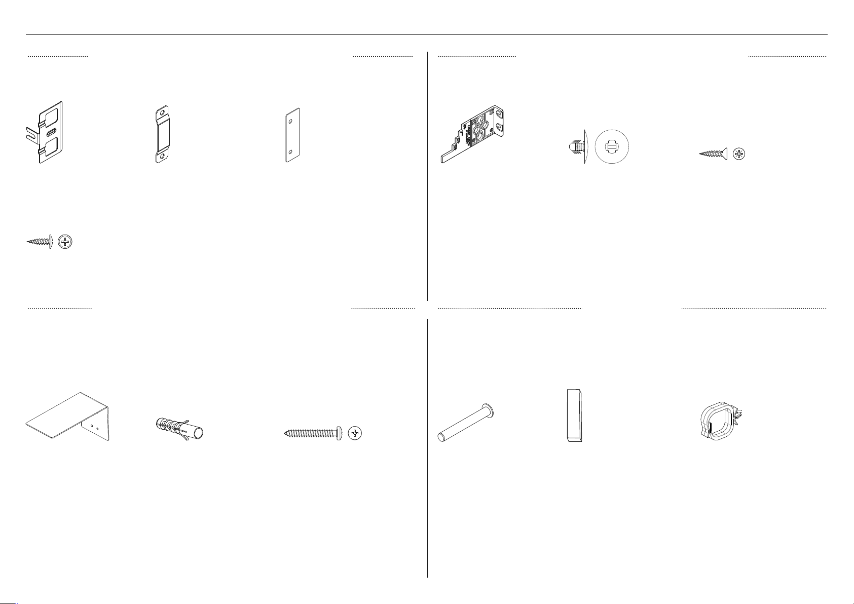
PIÈCES FOURNIES
ENSEMBLE DE FIXATION DE PANNEAU DE PORTE ENSEMBLE DE FIXATIONS D’INSTALLATION
Support latéral
(6)
Pour les panneaux de portes
sur mesure:
Vis cruciforme M5x12 (32)
ASSEMBLAGE DE SUPPORT ANTIBASCULEMENT
Support antibasculement
(1)
Pièce d’insertion pour support
(6)
Cheville pour maçonnerie
(4)
Pièce d’espacement de support
latéral
(6)
Vis cruciforme 10-12x35mm
(5)
Jauge d’alignement de
profondeur
(4)
Fournies dans des sacs distincts
Tige de limitation de charnière
(3)
Embout cannelé
(2)
PIÈCES DIVERSES
Joint d’étanchéité à l’air de la
plinthe
(1)
Vis à tête fraisée 8Gx16
(7)
Clip de blocage
(2)
81
Page 82

PIÈCES FOURNIES
ENSEMBLE D’INSTALLATION DE GARNITURES (BOÎTE EXTERNE)
Profilé latéral du panneau de porte supérieur
(2)
Profilé latéral du panneau de
tiroir inférieur (2)
Garniture latérale de bâti
(2)
Garniture supérieure de tiroir inférieur
(1)
EMBALLAGE D’ARTICLES DIVERS
ENSEMBLE DE FILTRE À EAU
Clip de blocage de collet
(1)
Tuyau tressé en acier inoxydable UNS de 7/16po
(11mm)
(1)
OUTILS FOURNIS
Filtre à eau
(1)
Adaptateur de 1/4po (6,35mm)
(2)
INTEGRATED COLUMN
WINE CABINET
RS2484VL2K1, RS2484VR2K1,
RS6121VL2K1, RS6121VR2K1
models
USER GUIDE
US CA NZ AU GB IE SG HK
8602A09.19
Guide d’utilisation
(6)
SERVICE & WARRANTY
SERVICE ET GARANTIE
ΣΈΡΒΙΣ ΚΑΙ ΕΓΓΎΗΣΗ
SERVIZIO E GARANZIA
SERVICE & GARANTIE
HUOLTO JA TAKUU
SERVICE OG GARANTI
保修和维修
݉ଡ଼ڸߴঔ
Service et garantie
(1)
82
COLONNE ENCASTRABLE
RÉFRIGÉRATEUR CONGÉLATEUR
Modèles RS2484WR, RS2484WL, RS3084WR
et RS3084WL
GUIDE D’INSTALLATION
US CA
86026A0.20
Guide d’installation
(1)
Clé pour porte
(1)
Clé hexagonale M4
(1)
Page 83

PIÈCES REQUISES
ENSEMBLE DE LIAISON POUR INSTALLATION PANNEAU DE PLINTHE
Utilisé pour l’installation double ou multiple avec plusieurs appareils. Peut être acheté
séparément auprès d’un détaillant Fisher&Paykel autorisé. Visitez le site fisherpaykel.com
pour plus d’informations.
Ensemble de fixation de liaison supérieure
Vis d’assemblage M5x20
(1)
Ensemble de fixation de liaison inférieure
Vis rondelle M6x16
(1)
Rondelle plate M5x16x1
(1)
Rondelle de plastique M6x12x3,2
(1)
Écrou hexagonal M6
(1)
PANNEAU DE PLINTHE
Non fourni; peut être acheté séparément auprès d’un détaillant Fisher&Paykel autorisé. Visitez
le site fisherpaykel.com pour plus d’informations.
z
La hauteur de la plinthe standard est de
102mm pour le panneau de porte en acier
inoxydable standard.
z
Pour l’installation d’un panneau de porte sur
mesure, une plinthe de 2 à 6po (50 à 152mm)
doit être fabriquée et ajustée en conséquence.
z
Une grille inférieure supplémentaire est
Panneau de plinthe (1)
requise pour l’installation d’une plinthe
de 2po (50mm). Vous pouvez vous
procurer la grille inférieure supplémentaire
(Pièce n° 847542P) en ligne sur le site
fisherpaykel.com.
OUTILS REQUIS
Non fourni; doit être fourni par l’installateur.
Visseuse électrique Tournevis à pointe plate Règle
Ensemble de support de liaison supérieure
Vis rondelle 8Gx16
(2)
Pièce d’espacement centrale
(1)
Scie à métaux Tournevis cruciforme Crayon
Couteau à lame rétractable Tournevis à pointe T20 étoilée Chariot manuel
83
Page 84

Ensemble de panneau de porte en acier
inoxydable
Non fourni; doit être acheté séparément
auprès d’un détaillant Fisher&Paykel
autorisé. Visitez le site fisherpaykel.com
pour plus d’informations.
MODÈLE D G
RS24 CA 25715 CA 25716
RS30 CA 25713 CA 25714
ENSEMBLES DE POIGNÉE DE PORTE ET TIROIRENSEMBLE DE PANNEAU DE PORTE
Non fourni; doit être acheté séparément auprès d’un détaillant Fisher&Paykel autorisé. Visitez
le site fisherpaykel.com pour plus d’informations. Sélectionnez parmi les options d’ensemble de
poignée ci-dessous:
ENSEMBLE DE POIGNÉE RS24 RS30
Poignée carrée fine en
aluminium (1)
Vis hexagonale M5x25
(4)
CA 25865 CA 25864
Pour les panneaux de portes
en acier inoxydable:
Vis rondelle 8Gx16 (32)
Ensemble de panneau de porte sur mesure
Fourni par les clients, adapté aux armoires.
Poignée carrée fine
noire (1)
Poignée carrée de
style professionnel (1)
Poignée carrée en
aluminium (1)
Poignée arrondie
en aluminium (1)
Poignée arrondie
de style professionnel (1)
Vis hexagonale M5x25
(4)
Vis hexagonale M5x25
(4)
Vis hexagonale M5x25
(4)
Vis hexagonale M5x25
(4)
Vis hexagonale M5x25
(4)
CA 25911 CA 25910
CA 25732 CA 25724
CA 25729 CA 25721
CA 25731 CA 25723
CA 25730 CA 25722
84
Poignée arrondie affleurante
de style professionnel (1)
Vis hexagonale M5x25
(4)
CA 25923 CA 25922
Page 85

ENSEMBLE DE CHANGEMENT DE CÔTÉ DES CHARNIÈRES
Non fourni; vendu séparément. Disponible en ligne sur le site fisherpaykel.com.
MODÈLE ENSEMBLE POUR CHARNIÈRE GAUCHE À
CHARNIÈRE DROITE
RS24 CA 848184P
RS30 CA 848184P
Cavité de charnière supérieure droite
(2)
Support adaptateur inférieur K05 droit
(1)
Support supérieur pour alcôve droit
(1)
Support adaptateur supérieur K05 droit
(1)
MODÈLE ENSEMBLE POUR CHARNIÈRE DROITE À
CHARNIÈRE GAUCHE
RS24 CA 848183P
RS30 CA 848183P
Cavité de charnière supérieure gauche
(2)
Support supérieur pour alcôve gauche
(1)
Support adaptateur inférieur K05 gauche
(1)
Support adaptateur supérieur K05 gauche
(1)
Support de charnière inférieure droite
(1)
Support de charnière inférieure gauche
(1)
85
Page 86

DIMENSIONS DU PRODUIT— MODÈLE RS24
A
B
C
DIMENSIONS DU PRODUIT PO MM
A Hauteur hors tout du produit 84 2134
B Largeur hors tout du produit 233/4 603
C Profondeur hors tout du produit (excluant le panneau de
porte avant)
POIDS DU PRODUIT LB KG
Poids (avec l’emballage) 357 162
Poids (sans l’emballage) 313 142
24 610
86
VUE DE FACE
VUE DE PROFIL
Page 87

DIMENSIONS DE LA CAVITÉ — MODÈLE RS24
ARMOIRES SANS MONTANT ARMOIRES AVEC MONTANT
Alignement de l’appareil au même niveau que les
armoires.
C
A
D
B
A
E
Alignement de l’appareil au même niveau que le montant des
armoires.
E
C
D
A
B
B
DIMENSIONS PO MM
A Hauteur hors tout de la cavité
B Largeur hors tout de la cavité
C Profondeur hors tout minimale de la cavité* 25 635
D Dégagement minimal des armoires à partir du bord des panneaux de portes 1/8 3
E Finition minimale requise 4102
* En supposant une épaisseur de panneau de porte de 3/4po (19mm).
84 2134
24 610
87
Page 88

DIMENSIONS DE PANNEAU DE PORTE— MODÈLE RS24
PANNEAU EN ACIER INOXYDABLE PANNEAU SUR MESURE
A
B
C
DIMENSIONS PO MM
A Hauteur du panneau de porte supérieur 493/8 1254
A
B
C
DIMENSIONS PO MM
A Hauteur du panneau de porte supérieur 493/8 1254
B Hauteur du panneau de tiroir inférieur 303/8 772
C Largeur du panneau de porte/tiroir 233/4 603
D Profondeur du panneau de porte (excluant la
poignée de porte)
POIDS DU PANNEAU DE PORTE LB KG
Poids du panneau de porte supérieur* 20 9
Poids du panneau de tiroir inférieur* 13 6
3/4 19
88
B Hauteur du panneau de tiroir inférieur 303/8 772
C Largeur du panneau de porte/tiroir 233/4 603
D Profondeur du panneau de porte (excluant la
poignée de porte)
POIDS DU PANNEAU DE PORTE LB KG
Poids du panneau de porte supérieur max. 34 max. 151/2
Poids du panneau de tiroir inférieur max. 21 max. 91/2
* Le poids maximal du panneau ne doit pas être dépassé.
min. 5/8
max. 1
min. 16
max. 25
Page 89

DIMENSIONS D’INSTALLATION DE PANNEAU DE PORTE SUR MESURE— MODÈLE RS24
Les dimensions sont indiquées pour la préparation et l’installation des panneaux de portes sur mesure. Pour les fichiers Dwg et Dxf de la préparation de panneau ci-dessous, téléchargez le dossier
sur thekitchentools.fisherpaykel.com.
z
L’épaisseur du panneau de porte sur mesure peut varier, à condition que les vis ne pénètrent pas au-delà de la profondeur totale du panneau de porte.
z
Les mesures des emplacements de trous de vis peuvent varier en fonction de la hauteur de la plinthe, de 50 à 152mm.
117/8po
(301,6mm)
8po (203,2mm)
2po (50,8mm)
11/2po (38,1mm)
15po (127mm)
20po (507,8mm)
2po (50mm)2po (50mm)
Ø2mm RÉF
10avant-trous recommandés
pour la fixation des supports.
(Ne perforez pas la surface
avant.)
2po (50mm)
31/2po (88mm)
11/2po (38,1mm)
117/8po
(301,6mm)
8po (203,2mm)
2po (50,8mm)
Ø2mm RÉF
10avant-trous recommandés
pour la fixation des supports.
(Ne perforez pas la surface
avant.)
2po (50mm)
493/8po
(1254mm)
43po (1092mm)
Assurez-vous d’installer la
poignée avec une distance de
29/16po (65mm) du bord
vers le centre du panneau, afin
d’éviter toute obstruction avec
le support.
11/4po (32,6mm)
233/4po
(603,2mm)
PANNEAU SUPÉRIEUR— VUE ARRIÈRE
303/8po
(771,5mm)
20po (508,4mm)
233/16po (588,4mm)
11/4po (32,6mm)
293/4po
(755,6mm)
PANNEAU INFÉRIEUR— VUE ARRIÈRE
Les ouvertures dans le support
d’accrochage sont destinées
uniquement aux poignées
Fisher&Paykel.
Si vous devez positionner une
poignée sur mesure dans la zone
ombragée illustrée ci-dessus,
assurez-vous que les têtes de vis
de la poignée soient renfoncées
dans la partie arrière du panneau
de porte pour éviter toute
obstruction avec le support
d’accrochage.
89
Page 90

DÉGAGEMENT DE LA PORTE — MODÈLE RS24
OUVERTURE DE LA PORTE À 115° OUVERTURE DE LA PORTE À 90°
ACCÈS COMPLET À
L’INTÉRIEUR
B
C
Insertion de la tige de limitation
de charnière
Avant de pousser l’appareil dans
A
A
les armoires, insérez la tige de
limitation de charnière fournie dans
le trou de la charnière supérieure.
La tige de limitation de charnière
permet de limiter la rotation de
MUR
porte à
MUR
ACCÈS LIMITÉ À
L’INTÉRIEUR
90°.
DIMENSIONS PO MM
A Largeur de la porte (ouverture à 90°) mesurée à partir du devant de la porte 26 660
B Dégagement minimal de la porte* par rapport au mur adjacent** (115°— accès
complet à l’intérieur)
C Dégagement minimal de la porte* par rapport au mur adjacent** (90°— accès
réduit à l’intérieur)
14 356
45/16 110
90
Page 91

DÉGAGEMENT DU TIROIR — MODÈLE RS24
DIMENSIONS PO MM
A Extension maximale du tiroir lors de l’ouverture (excluant la
poignée)
B Extension maximale du tiroir lors de l’ouverture (incluant la
poignée)
153/4 400
181/8 461
B
A
91
Page 92
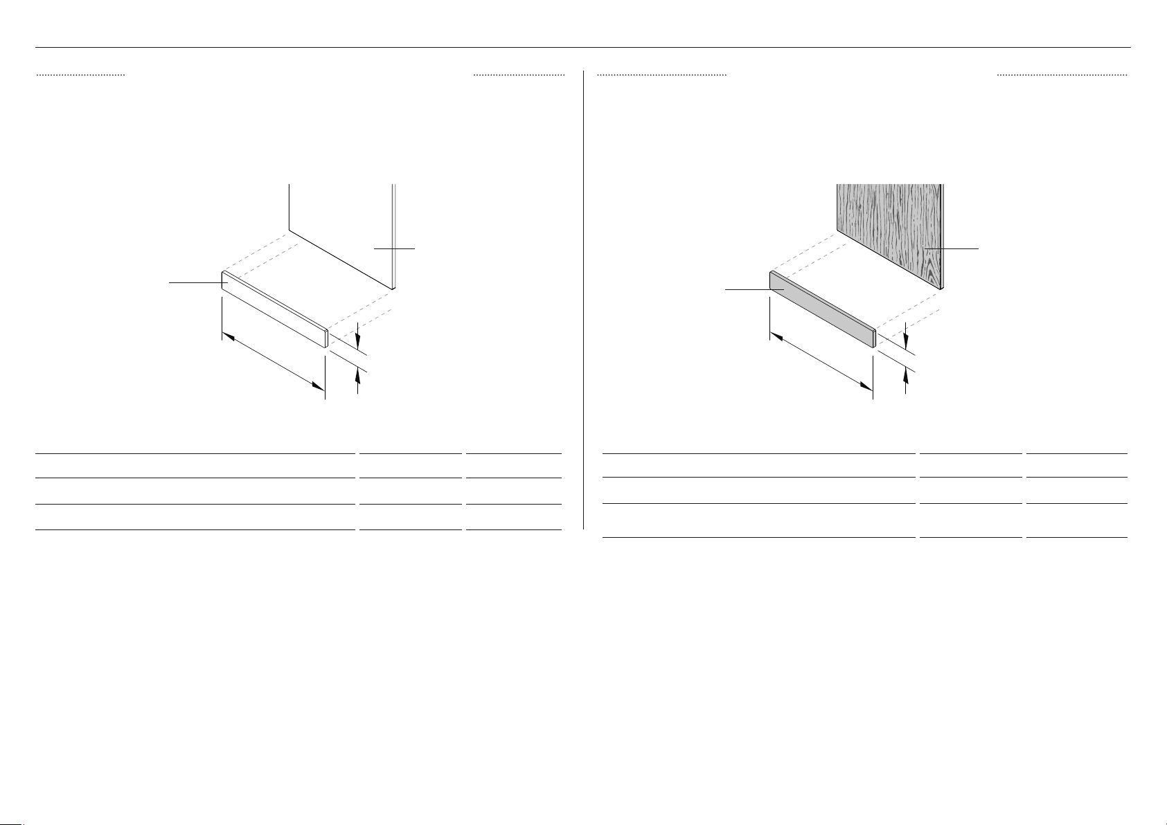
DIMENSIONS DE LA PLINTHE — MODÈLE RS24
PANNEAU DE PLINTHE EN ACIER INOXYDABLE PANNEAU DE PLINTHE SUR MESURE
Peut être acheté séparément auprès d’un détaillant Fisher&Paykel autorisé. Visitez le site
fisherpaykel.com pour plus d’informations.
panneau de porte
panneau de plinthe
A
PANNEAU DE PLINTHE (CA 25390)
DIMENSIONS PO MM
A Largeur de la plinthe 237/8 606
B Hauteur de la plinthe 4 102
B
Pour l’installation d’un panneau de porte sur mesure, une plinthe sur mesure de 2 à 6po (50
à 152mm) peut être fabriquée et ajustée par un ébéniste. La hauteur du panneau de porte sur
mesure doit être ajustée en conséquence. Des grilles inférieures supplémentaires sont requises
pour l’installation d’une plinthe de 2po (50mm).
panneau de porte
panneau de plinthe
A
DIMENSIONS PO MM
A Largeur de la plinthe 237/8 606
B Hauteur de la plinthe* min. 2 - max. 6
B
min. 51 - max.
152
92
Page 93

OPTIONS D’INSTALLATION DE LA PLINTHE
La hauteur de la plinthe
standard est de 4po (102mm)
avec le panneau de porte en
acier inoxydable.
Pour une plinthe sur mesure
d’une hauteur de 2po (50mm)
(grille inférieure supplementaire
fixee).
Pour une plinthe sur mesure
d’une hauteur de 6po
(152mm).
Profondeur de plinthe de min.
27/8po (73mm) à max. 4po
(102mm) mesurée à partir de
l’arrière du panneau de porte
panneau de
plinthe
93
Page 94

DIMENSIONS DU PRODUIT— MODÈLE RS30
A
B
C
DIMENSIONS DU PRODUIT PO MM
A Hauteur hors tout du produit 84 2134
B Largeur hors tout du produit 293/4 756
C Profondeur hors tout du produit (excluant le panneau de
porte avant)
POIDS DU PRODUIT LB KG
Poids (avec l’emballage) 406 184
Poids (sans l’emballage) 357 162
24 610
94
VUE DE FACE
VUE DE PROFIL
Page 95

DIMENSIONS DE LA CAVITÉ — MODÈLE RS30
ARMOIRES SANS MONTANT ARMOIRES AVEC MONTANT
Alignement de l’appareil au même niveau que les
armoires.
C
A
B
D
A
E
Alignement de l’appareil au même niveau que le montant des
armoires.
E
C
D
A
B
B
DIMENSIONS PO MM
1 Hauteur hors tout de la cavité
2 Largeur hors tout de la cavité
3 Profondeur hors tout minimale de la cavité* 25 635
4 Dégagement minimal des armoires à partir du bord des panneaux de portes 1/8 3
5 Finition minimale requise 4102
* En supposant une épaisseur de panneau de porte de 3/4po (19mm).
84 2134
30 762
95
Page 96

DIMENSIONS DE PANNEAU DE PORTE— MODÈLE RS30
PANNEAU EN ACIER INOXYDABLE PANNEAU SUR MESURE
A
A
B
B
C
DIMENSIONS PO MM
A Hauteur du panneau de porte supérieur 493/8 1254
B Hauteur du panneau de porte de tiroir 303/8 772
C Largeur du panneau de porte 293/4 756
D Profondeur du panneau de porte
(excluant la poignée de porte)
POIDS DU PANNEAU DE PORTE LB KG
Poids de la porte supérieure 22 10
Poids de la porte de tiroir inférieur 15 7
3/4 19
96
C
DIMENSIONS PO MM
A Hauteur du panneau de porte supérieur 493/8 1254
B Hauteur du panneau de porte de tiroir 303/8 772
C Largeur du panneau de porte 293/4 756
D Profondeur du panneau de porte
(excluant la poignée de porte)
POIDS DU PANNEAU DE PORTE LB KG
Poids de la porte supérieure max. 41 max. 181/2
Poids de la porte de tiroir inférieur max. 25 max. 111/2
min. 5/8
max. 1
min. 16
max. 25
Page 97

DIMENSIONS D’INSTALLATION DE PANNEAU DE PORTE SUR MESURE— MODÈLE RS30
Les dimensions sont indiquées pour la préparation et l’installation des panneaux de portes sur mesure. Pour les fichiers Dwg et Dxf de la préparation de panneau ci-dessous, téléchargez le dossier
sur thekitchentools.fisherpaykel.com.
z
L’épaisseur du panneau de porte sur mesure peut varier, à condition que les vis ne pénètrent pas au-delà de la profondeur totale du panneau de porte.
z
Les mesures des emplacements de trous de vis peuvent varier en fonction de la hauteur de la plinthe, de 50 à 152mm.
147/8po
(377,8mm)
8po (203,2mm)
2po (50,8mm)
2po (50mm)
15po (127mm)
Ø2mm RÉF
10avant-trous recommandés
pour la fixation des supports.
(Ne perforez pas la surface
avant.)
20po (507,8mm)
31/2po (88mm)
11/2po (38,1mm)
147/8po
(377,8mm)
8po (203,2mm)
2po (50,8mm)
Ø2mm RÉF
10avant-trous recommandés
pour la fixation des supports.
(Ne perforez pas la surface
avant.)
2po (50mm)
493/8po
(1254mm)
43po (1092mm)
2po (50mm)
2po (50mm)
293/4po
(755,6mm)
PANNEAU SUPÉRIEUR— VUE ARRIÈRE
Assurez-vous d’installer la
poignée avec une distance de
65mm entre le bord du panneau
et le centre, afin d’éviter toute
obstruction avec le support.
11/4po (32,6mm)
303/8po
(771,5mm)
233/16po (588,4mm)
20po (508,4mm)
11/4po (32,6mm)
293/4po
(755,6mm)
PANNEAU INFÉRIEUR— VUE ARRIÈRE
Les ouvertures dans le support
d’accrochage sont destinées
uniquement aux poignées
Fisher&Paykel.
Si vous devez positionner une
poignée sur mesure dans la zone
ombragée illustrée ci-dessus,
assurez-vous que les têtes de vis
de la poignée soient renfoncées
dans la partie arrière du panneau
de porte pour éviter toute
obstruction avec le support
d’accrochage.
97
Page 98

DÉGAGEMENT DE LA PORTE — MODÈLE RS30
OUVERTURE DE LA PORTE À 115° OUVERTURE DE LA PORTE À 90°
ACCÈS COMPLET À
L’INTÉRIEUR
B
C
Insertion de la tige de limitation
de charnière
Avant de pousser l’appareil dans
les armoires, insérez la tige de
A
A
limitation de charnière fournie dans
le trou de la charnière supérieure.
La tige de limitation de charnière
permet de limiter la rotation de
MUR
porte à
MUR
ACCÈS LIMITÉ À
L’INTÉRIEUR
90°.
DIMENSIONS PO MM
A Largeur de la porte (ouverture à 90°) mesurée à partir du devant de la porte 32 813
B Dégagement minimal de la porte* par rapport au mur adjacent** (115°— accès
complet à l’intérieur)
C Dégagement minimal de la porte* par rapport au mur adjacent** (90°— accès
réduit à l’intérieur)
161/2 419
45/16 110
98
Page 99

DÉGAGEMENT DU TIROIR — MODÈLE RS30
DIMENSIONS PO MM
A Extension maximale du tiroir lors de l’ouverture (excluant la
poignée)
B Extension maximale du tiroir lors de l’ouverture (incluant la
poignée)
153/4 400
181/8 461
B
A
99
Page 100

DIMENSIONS DE LA PLINTHE — MODÈLE RS30
PANNEAU DE PLINTHE EN ACIER INOXYDABLE PANNEAU DE PLINTHE SUR MESURE
Peut être acheté séparément auprès d’un détaillant Fisher&Paykel autorisé. Visitez le site
fisherpaykel.com pour plus d’informations.
panneau de porte
panneau de plinthe
A
PANNEAU DE PLINTHE (CA 25392)
DIMENSIONS PO MM
A Largeur de la plinthe 297/8 759
B
Pour l’installation d’un panneau de porte sur mesure, une plinthe sur mesure de 2 à 6po (50
à 152mm) peut être fabriquée et ajustée par un ébéniste. La hauteur du panneau de porte sur
mesure doit être ajustée en conséquence. Des grilles inférieures supplémentaires sont requises
pour l’installation d’une plinthe de 2po (50mm).
panneau de porte
panneau de plinthe
A
DIMENSIONS PO MM
A Largeur de la plinthe 297/8 759
B
B Hauteur de la plinthe 4 102
100
B Hauteur de la plinthe* 2-6 51 - 152
 Loading...