

Page 1
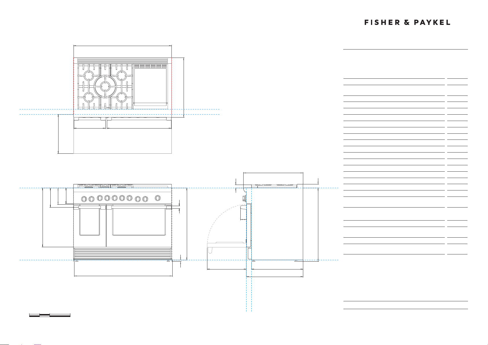
CABINET FACE FOR
min 35 3/4"
max 36 3/4"
47 7/8"
29 1/8"
25 1/8"
27 11/16"
1 9/16"
1 3/4"
7 3/4"
8 1/16"
9 7/16"
28 7/8"
35 1/4"
1 1/4"
15 1/16"
31 1/2"
3 1/16"
19 1/8"
min 1/2"
max 1 1/2"
min 35 3/4"
max 36 3/4"
min 48"
max 25 1/8"
max 27 11/16"
INSTALLATION WITH
PROJECTING CONTROL PANEL
CABINET FACE FOR
INSTALLATION WITH
FLUSH CONTROL PANEL
DATUM :
TOP OF
COUNTERTOP
K J I H
DATA SHEET
B
47 7/8"
Model no:
RGV2-485GD-N, RGV2GD-485-L
RDV2-485GD-N, RDV2GD-485-L
(refer page 3 for metric measurements)
C
29 1/8"
q
on
PLAN VIEW
29 1/8"
C
GF
m
Product Dimensions in
A Overall height of range (from floor to cooktop,
excludinggrates and vent trim)
B Overall width of range
C Overall depth of range (excluding handle and dials)
D Depth from rear of chassis to cabinetry face – projecting
E Depth from rear of chassis to cabinetry face – flush
F Height from countertop to top of pan supports
G Height from countertop to top of vent trim
H Height from countertop to bottom of control panel
I Height from countertop to top of door
J Height from countertop to center of handle
K Height from countertop to bottom of door
L Height from countertop to bottom of chassis
M Thickness of handles (not including standoffs)
N Width of left handle (including standoffs)
O Width of right handle (including standoffs)
P Depth of handle (measured from front of door)
Q Depth of open door to cabinetry face – flush
R Adjustable feet height
48" Professional Range
DATUM : BOTTOM OF CHASSIS
0 5 10 20
inches
B
47 7/8"
FRONT VIEW
A
l
r
p
Dq
35 3/4" 36 3/4"
Cavity Dimensions in
Overall height of cavity
Overall width of cavity
Overall depth of cavity for projecting control panel
Overall depth of cavity for flush control panel
E
PROFILE VIEW
INDICATES PRODUCT DATUM -------------------------------------------
CABINET FACE FOR INSTALLATION
WITH FLUSH CONTROL PANEL
CABINET FACE FOR INSTALLATION
WITH PROJECTING CONTROL PANEL
DATE: 24.04.2018
IMPORTANT: Throughout this guide, dimensions may vary by ±2mm (1/16").
Read the installation guide for detailed information on installing the product.
For full installation instructions and specifications visit fisherpaykel.com
Page 2
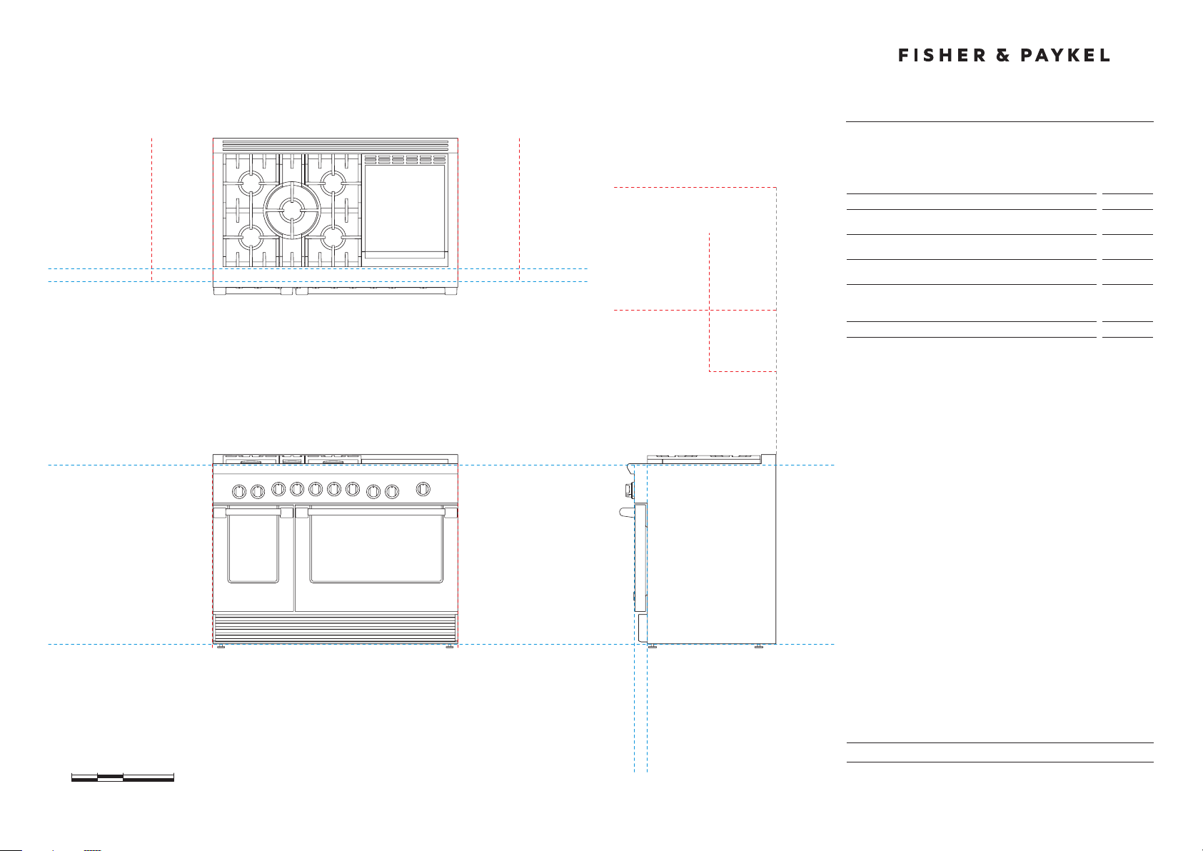
DATA SHEET
48"
18"
12"
54"
30"
13"
48" Professional Range
MINIMUM CLEARANCE:
MINIMUM CLEARANCE:
NEAREST VERTICAL
NEAREST VERTICAL
COMBUSTIBLE SURFACE
COMBUSTIBLE SURFACE
CABINET FACE FOR
INSTALLATION WITH
PROJECTING CONTROL PANEL
CABINET FACE FOR
INSTALLATION WITH
FLUSH CONTROL PANEL
DATUM :
TOP OF COUNTERTOP
PLAN VIEW
MINIMUM CLEARANCE:
CC
NEAREST VERTICAL
COMBUSTIBLE SURFACE
MINIMUM CLEARANCE:
D
COMBUSTIBLE SURFACE
MAXIMUM OVERALL DEPTH
E
OF OVERHEAD CABINETRY
MINIMUM CLEARANCE:
D
NON-COMBUSTIBLE SURFACE
MINIMUM CLEARANCE:
B
ADJACENT OVERHEAD CABINET
Model no:
RGV2-485GD-N, RGV2-485GD-L
RDV2-485GD-N, RDV2-485GD-L
(refer page 4 for metric measurements)
Clearance Dimensions in
A Minimum width of ventilation hood installed above range
–not shown*
B Minimum vertical distance between countertop and cabinet
extending above counter
C Minimum clearance from left and right edge of range to
nearest vertical combustible surface
D Minimum clearance from cooking surface to:
– combustible surface centered above the cooking surface
– non-combustible surface centered above the cooking surface
E Maximum overall depth of overhead cabinetry
DATUM : BOTTOM OF CHASSIS
0 5 10 20
inches
FRONT VIEW PROFILE VIEW
CABINET FACE FOR INSTALLATION
WITH FLUSH CONTROL PANEL
CABINET FACE FOR INSTALLATION
WITH PROJECTING CONTROL PANEL
INDICATES CABINETRY CLEARANCES --------------------------------
INDICATES PRODUCT DATUM -------------------------------------------
DATE: 24.04.2018
IMPORTANT: Throughout this guide, dimensions may vary by ±2mm (1/16").
Read the installation guide for detailed information on installing the product.
For full installation instructions and specifications visit fisherpaykel.com
Page 3
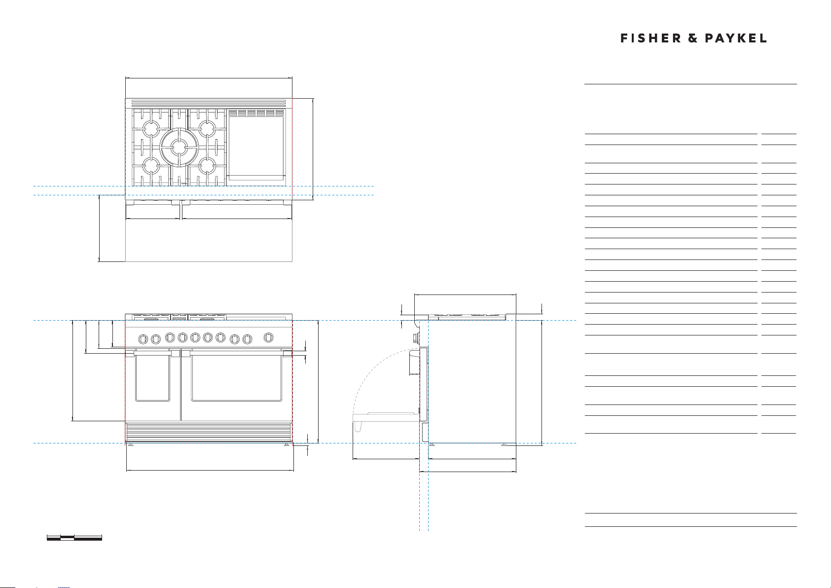
CABINET FACE FOR
min 908
max 933
1216
740
638
703
40
45
196
204
240
734
895
32
393
801
77
486
min 13
max 38
min 908
max 933
min 1219
max 638
max 703
INSTALLATION WITH
PROJECTING CONTROL PANEL
CABINET FACE FOR
INSTALLATION WITH
FLUSH CONTROL PANEL
DATUM :
TOP OF
COUNTERTOP
K J I H
DATA SHEET
1216
B
Model no:
RGV2-485GD-N, RGV2-485GD-L
RDV2-485GD-N, RDV2-485GD-L
(refer page 1 for imperial measurements)
C
740
q
on
PLAN VIEW
740
C
GF
m
Product Dimensions mm
A Overall height of range (from floor to cooktop,
excludinggrates and vent trim)
B Overall width of range
C Overall depth of range (excluding handle and dials)
D Depth from rear of chassis to cabinetry face – projecting
E Depth from rear of chassis to cabinetry face – flush
F Height from countertop to top of pan supports
G Height from countertop to top of vent trim
H Height from countertop to bottom of control panel
I Height from countertop to top of door
J Height from countertop to centre of handle
K Height from countertop to bottom of door
L Height from countertop to bottom of chassis
M Thickness of handles (not including standoffs)
N Width of left handle (including standoffs)
O Width of right handle (including standoffs)
P Depth of handle (measured from front of door)
Q Depth of open door to cabinetry face – flush
R Adjustable feet height
48" Professional Range
DATUM : BOTTOM OF CHASSIS
0 100 200 400
millimetres
B
1216
FRONT VIEW
A
l
r
p
Dq
908 933
Cavity Dimensions mm
Overall height of cavity
Overall width of cavity
Overall depth of cavity for projecting control panel
Overall depth of cavity for flush control panel
E
PROFILE VIEW
INDICATES PRODUCT DATUM -------------------------------------------
CABINET FACE FOR INSTALLATION
WITH FLUSH CONTROL PANEL
CABINET FACE FOR INSTALLATION
WITH PROJECTING CONTROL PANEL
DATE: 24.04.2018
IMPORTANT: Throughout this guide, dimensions may vary by ±2mm (1/16").
Read the installation guide for detailed information on installing the product.
For full installation instructions and specifications visit fisherpaykel.com
Page 4
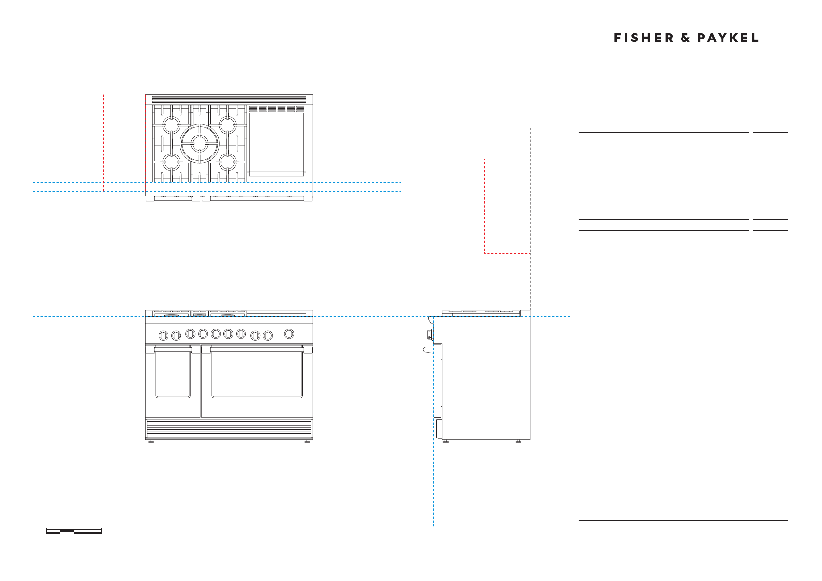
DATA SHEET
1219
457
305
1372
762
330
48" Professional Range
MINIMUM CLEARANCE:
NEAREST VERTICAL
COMBUSTIBLE SURFACE
CABINET FACE FOR
INSTALLATION WITH
PROJECTING CONTROL PANEL
CABINET FACE FOR
INSTALLATION WITH
FLUSH CONTROL PANEL
DATUM :
TOP OF COUNTERTOP
PLAN VIEW
MINIMUM CLEARANCE:
CC
NEAREST VERTICAL
COMBUSTIBLE SURFACE
MINIMUM CLEARANCE:
D
COMBUSTIBLE SURFACE
MAXIMUM OVERALL DEPTH
E
OF OVERHEAD CABINETRY
MINIMUM CLEARANCE:
D
NON-COMBUSTIBLE SURFACE
MINIMUM CLEARANCE:
B
ADJACENT OVERHEAD CABINET
Model no:
RGV2-485GD-N, RGV2-485GD-L
RDV2-485GD-N, RDV2-485GD-L
(refer page 2 for imperial measurements)
Clearance Dimensions mm
A Minimum width of ventilation hood installed above range
–not shown*
B Minimum vertical distance between countertop and cabinet
extending above counter
C Minimum clearance from left and right edge of range to
nearest vertical combustible surface
D Minimum clearance from cooking surface to:
– combustible surface centred above the cooking surface
– non-combustible surface centred above the cooking surface
E Maximum overall depth of overhead cabinetry
DATUM : BOTTOM OF CHASSIS
0 100 200 400
millimetres
FRONT VIEW PROFILE VIEW
CABINET FACE FOR INSTALLATION
WITH FLUSH CONTROL PANEL
CABINET FACE FOR INSTALLATION
WITH PROJECTING CONTROL PANEL
INDICATES CABINETRY CLEARANCES --------------------------------
INDICATES PRODUCT DATUM -------------------------------------------
DATE: 24.04.2018
IMPORTANT: Throughout this guide, dimensions may vary by ±2mm (1/16").
Read the installation guide for detailed information on installing the product.
For full installation instructions and specifications visit fisherpaykel.com
 Loading...