

Fisher & Paykel RDV2-486GD, RGV2-486GL, RDV2-486GL, RGV2-485GD, RDV2-485GD Installation Manual
...Page 1

PROFESSIONAL RANGE
RDV2 & RGV2
models
INSTALLATION GUIDE
US CA
591090E07.18
Page 2
!
WARNING!
If the information in this manual is not
followed exactly, a fire or explosion may
result causing property damage, personal
injury or death.
Do not store or use gasoline or other flammable
vapors and liquids in the vicinity of this or any
other appliance.
NEVER use this appliance as a space heater to
heat or warm the room. Doing so may result in
carbon monoxide poisoning and overheating of
the appliance.
WHAT TO DO IF YOU SMELL GAS
●
Do not try to light any appliance.
●
Do not touch any electrical switch.
●
Do not use any phone in your building.
●
Immediately call your gas supplier
from a neighbor’s phone.
Follow the gas supplier’s instructions.
●
If you cannot reach your gas supplier,
call the fire department.
Installation and service must be performed
by a qualified installer, service agency or the
gas supplier.
Page 3
1SAFETY AND WARNINGS
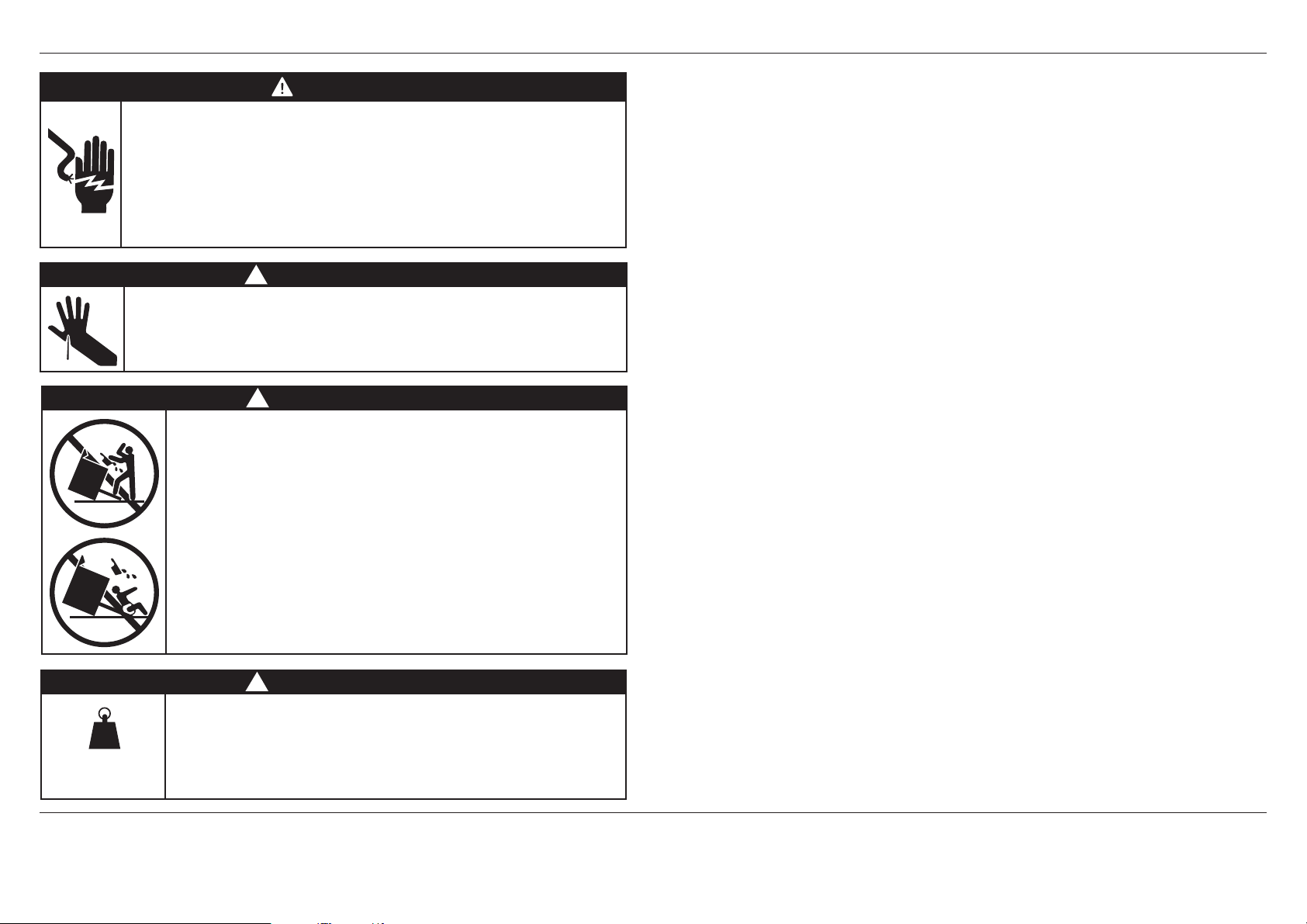
Electrical shock hazard
Before carrying out any work on the electrical section of the appliance,
it must be disconnected from the mains electricity supply.
Connection to a good ground wiring system is absolutely essential
and mandatory.
Alterations to the domestic wiring system must only be made by a
qualified electrician
Failure to follow this advice may result in electrical shock or death.
Cut Hazard
Take care – panel edges are sharp.
Failure to use caution could result in injury or cuts.
420-630 lb
190-285 kg
WARNING!
!
WARNING!
!
WARNING!
To reduce the risk of tipping the appliance, the appliance must
be secured by properly installed anti-tip device packed with the
appliance.
●
A child or adult can tip the range and be killed.
●
Install the anti-tip device to the structure by fastening the
supplied bracket to the floor and wall following the instructions
for installing the anti-tip device.
●
Engage the anti-tip device.
●
Re-engage the anti-tip device if the range is moved.
●
See installation instructions for details.
Failure to do so can result in death or serious burns to children
of adults.
!
WARNING!
Extremely Heavy
Proper equipment and adequate manpower must be used in moving
the range to avoid personal injury or damage to the unit or the
floor. The unit is heavy and rests on adjustable steel legs.
Failure to follow this advice may result in damage or personal injury.
IMPORTANT SAFETY INSTRUCTIONS!
●
Save these instructions for the local inspectors use.
●
To avoid hazard, follow these instructions carefully before installing or using this appliance.
●
Please make this information available to the person installing the appliance – doing so could
reduce your installation costs.
●
This range is to be installed and connected to the electricity supply only by an authorized
person.
●
If the installation requires alterations to the domestic electrical system, call a qualified
electrician. The electrician should also check that the socket cable section is suitable for the
electricity drawn by the range.
●
Service should only be done by authorized technicians. Technicians must disconnect the
power supply before servicing this appliance.
●
The range must be grounded.
●
Installation must comply with your local building and electricity regulations.
●
This appliance must be installed and connected to the mains power supply only by a suitably
qualified person according to these installation instructions and in compliance with any
applicable local building and electricity regulations. Failure to install the appliance correctly
could invalidate any warranty or liability claims.
●
Ensure the installer shows the customer where the gas supply shut-off valve is located.
●
If the power supply cable is damaged, it must be replaced by the manufacturer, its service
agent or similarly qualified person in order to avoid a hazard.
●
A circuit breaker is recommended.
●
Do not use adaptors, reducers or branching devices to connect the oven to the mains
electricity supply, as they can cause overheating and burning.
●
Improper installation, adjustment alteration, service or maintenance can cause property
damage, injury or death. Read the installation, operating and maintenance instructions
thoroughly before using, installing or servicing this appliance.
●
A risk of the appliance tipping over exists if the appliance is not installed in accordance with
installation instructions.
●
DO NOT obstruct the flow of combustion or ventilation air to the appliance. Be sure a fresh air
supply is available.
●
California Proposition 65 – The burning of gas cooking fuel generates some by-products which
are known by the State of California to cause cancer or reproductive harm. California law
requires businesses to warn customers of potential exposure to such substances. To minimize
exposure to these substances, always operate this unit according to the manufacturer’s
instructions and provide good ventilation to the room when cooking with gas.
●
Check local building codes for the proper method of range installation. Local codes vary.
Installation, electrical connections, and grounding must comply with all applicable codes.
In the absence of local codes, the range should be installed in accordance with the latest
edition of National Fuel Gas Code ANSI Z223.1 and National Electrical Code ANSI / NFPA 70.
●
In Canada: Installation must be in accordance with the current CAN/CGA B149.1 & 2 Gas
Installation codes and/or local codes. Electrical installation must be in accordance with the
current CSA C22.1 Canadian Electrical Codes Part 1 and/or local codes.
●
Be sure that the unit being installed is set up for the kind of gas being used. The gas range
is shipped from the factory set and adjusted for Natural Gas or LP (propane), depending on
the specific model ordered. Verify that the range is compatible with the gas at the installation
site before proceeding further. Return range to dealer if the unit is not set for site gas supply.
●
The appliance must not be installed behind a decorative door in order to avoid overheating.
IMPORTANT!
SAVE THESE INSTRUCTIONS
The models shown in this installation guide may not be available in all markets and are subject to change at any time. For current details about model and specification availability in your country, please go to our
website www.fisherpaykel.com or contact your local Fisher & Paykel dealer.
3
Page 4
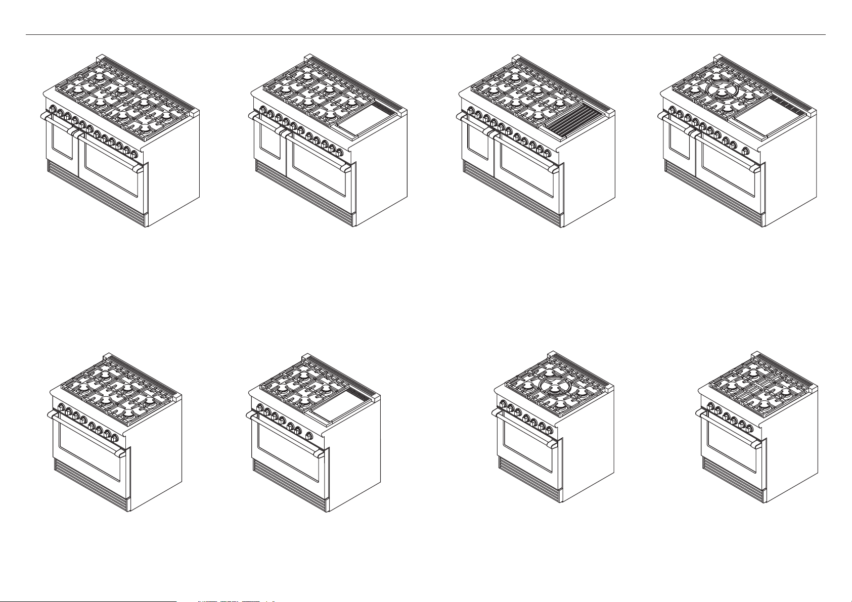
48” MODELS
2MODEL IDENTIFICATION
RGV2-488
RDV2-488
36” MODELS
RGV2-486GD
RDV2-486GD
RGV2-486GL
RDV2-486GL
30” MODELS
RGV2-485GD
RDV2-485GD
4
RGV2-366
RDV2-366
RGV2-364GD
RDV2-364GD
RGV2-305
RDV2-305
RGV2-304
RDV2-304
Page 5
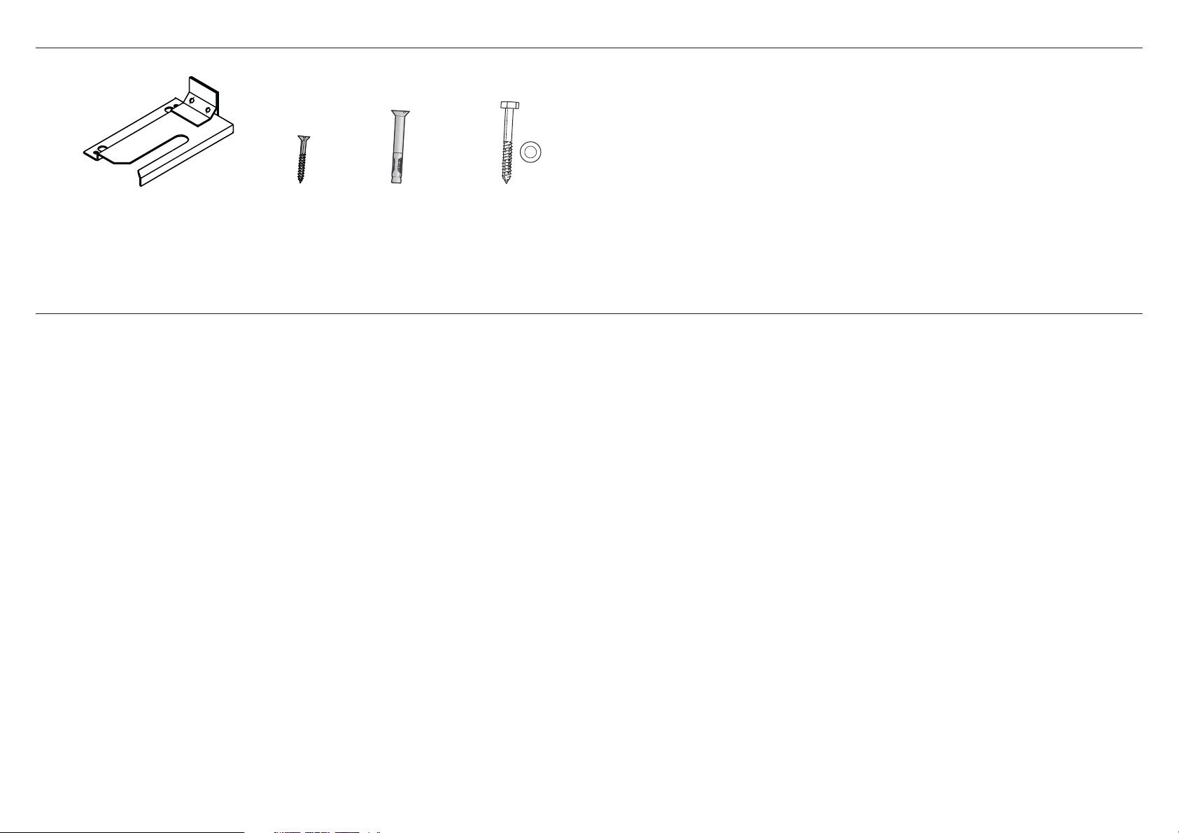
3PARTS SUPPLIED FOR INSTALLATION
Anti-tip bracket (1) 5/16” x 1 1/2”
#10 x 2”
wood screws (4)
sleeve anchors (2)
Lag bolts and
washers (2)
4UNPACKING AND HANDLING THE RANGE
Unpacking and handling
●
Inspect the product to verify that there is no shipping damage. If any damage is detected, call the shipper and initiate a damage claim. Fisher & Paykel is not responsible for shipping damage.
●
DO NOT discard any packing material (box, pallet, straps) until the unit has been inspected.
●
Remove the outer carton and any packing material from the shipping base.
IMPORTANT!
●
DO NOT lift range by the oven door handles!
●
DO NOT remove the grill or griddle assemblies!
5
Page 6
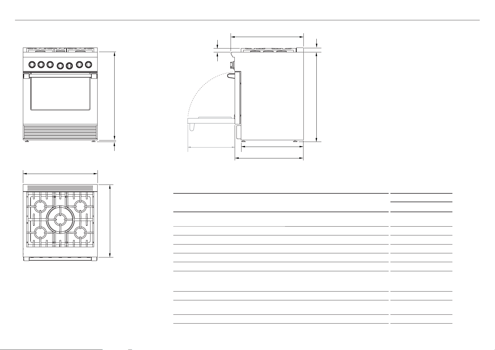
B
C
C
F
H
I
D
J
E
G
A
FRONT
5PRODUCT DIMENSIONS – 30” MODELS
PROFILE
RGV2-305 shown for Illustration purposes only
PRODUCT DIMENSIONS
PLAN
6
Overall height of range (from floor to cooktop, excluding
A
pan supports and vent trim)
Overall width of range 29 7/8” (759)
B
Overall depth of range (excluding handle and dials) 29 1/8” (740)
C
Depth from rear of chassis to cabinetry face – projecting control panel 25 1/8” (638)
D
Depth from rear of chassis to cabinetry face – flush control panel 27 11/16” (703)
E
Height from top of countertop to top of pan supports 1 9/16” (40)
F
Height from top of countertop to top of
G
- vent trim (if fitted)
- angled vent trim (if fitted)
Height from top of countertop to bottom of chassis 35 1/4” (895)
H
Adjustable feet height min 1/2’’ (13)
I
Depth of open door to front control panel 19 1/8” (486)
J
30” MODELS
inches (mm)
min 35 3/4’’ (908)
max 36 3/4’’ (933)
1 3/4” (45)
3 1/2” (90)
max 1 1/2’’ (38)
Page 7

B
C
H
I
C
F
D
J
E
G
A
FRONT
5PRODUCT DIMENSIONS – 36” MODELS
PROFILE
RGV2-364GD shown for Illustration purposes only
PLAN
PRODUCT DIMENSIONS
Overall height of range (from floor to cooktop, excluding
A
pan supports and vent trim)
Overall width of range 35 7/8” (911)
B
Overall depth of range (excluding handle and dials) 29 1/8” (740)
C
Depth from rear of chassis to cabinetry face – projecting control panel 25 1/8” (638)
D
Depth from rear of chassis to cabinetry face – flush control panel 27 11/16” (703)
E
Height from top of countertop to top of pan supports 1 9/16” (40)
F
Height from top of countertop to top of
G
- vent trim (if fitted)
- angled vent trim (if fitted)
Height from top of countertop to bottom of chassis 35 1/4” (895)
H
Adjustable feet height min 1/2’’ (13)
I
Depth of open door to front control panel 19 1/8” (486)
J
36” MODELS
inches (mm)
min 35 3/4’’ (908)
max 36 3/4’’ (933)
3 1/2” (90)
max 1 1/2’’ (38)
1 3/4” (45)
7
Page 8
B
C
H
I
C
F
D
J
E
G
A
FRONT
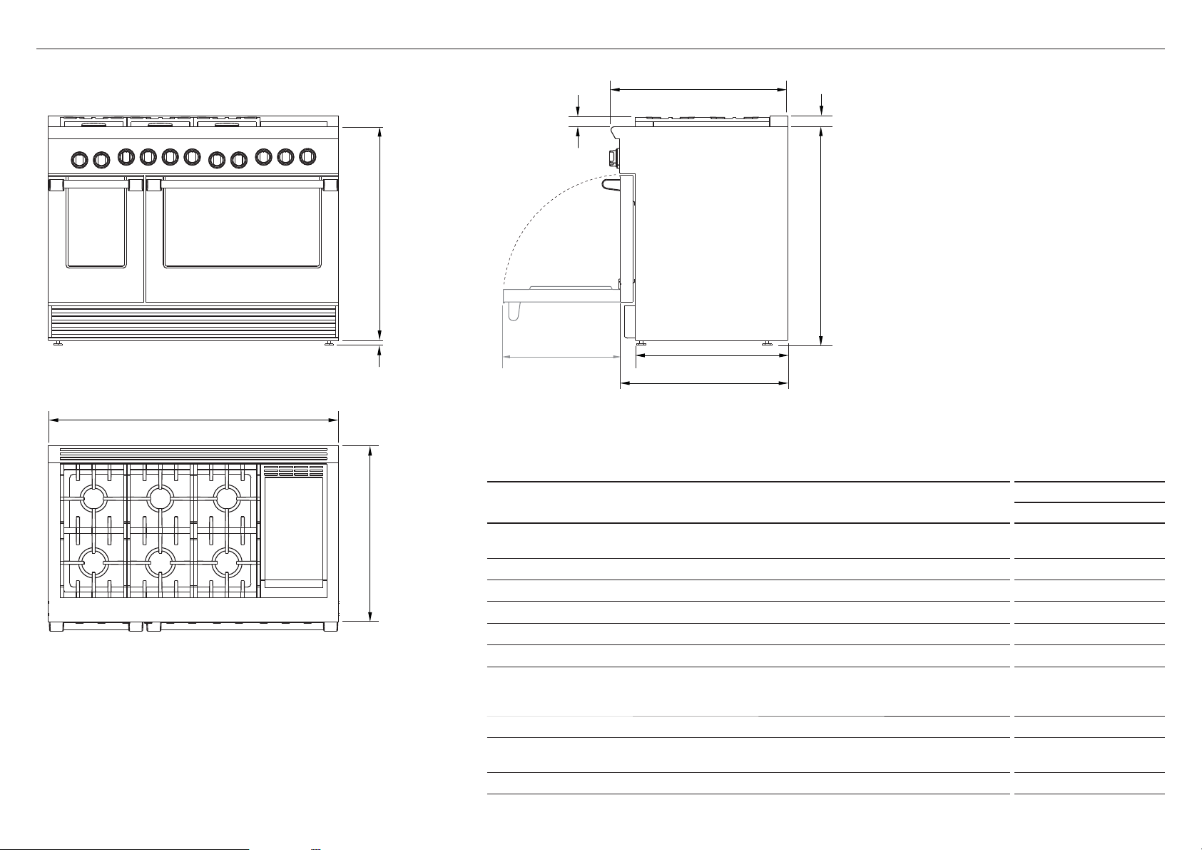
5PRODUCT DIMENSIONS – 48” MODELS
PROFILE
RGV2-486GD shown for Illustration purposes only
48” MODELS
inches (mm)
min 35 3/4’’ (908)
max 36 3/4’’ (933)
1 3/4” (45)
3 1/2” (90)
max 1 1/2’’ (38)
PLAN
PRODUCT DIMENSIONS
Overall height of range
A
(from floor to cooktop, excluding pan supports and vent trim)
Overall width of range 47 7/8” (1216)
B
Overall depth of range (excluding handle and dials) 29 1/8” (740)
C
Depth from rear of chassis to cabinetry face – projecting control panel 25 1/8” (638)
D
Depth from rear of chassis to cabinetry face – flush control panel 27 11/16” (703)
E
Height from top of countertop to top of pan supports 1 9/16” (40)
F
Height from top of countertop to top of
G
- vent trim (if fitted)
- angled vent trim (if fitted)
Height from top of countertop to bottom of chassis 35 1/4” (895)
H
Adjustable feet height min 1/2’’ (13)
I
Depth of open door to front control panel 19 1/8” (486)
J
8
Page 9
E
H
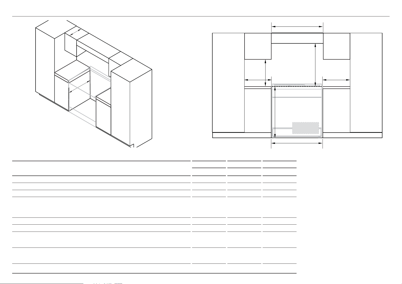
6CLEARANCE DIMENSIONS – ALL MODELS
A
D
B
CC
COOKING SURFACE
G
ISO
CLEARANCE DIMENSIONS
Minimum width of ventilation hood installed above range 30’’ (762) 36’’ (914) 48’’ (1219)
A
Minimum vertical distance between countertop and cabinet extending above counter
B
Minimum clearance from left and right edge of range to nearest vertical combustible surface 12” (305) 12” (305) 12” (305)
C
Minimum clearance from cooking surface to:
D
- combustible surface centered above the cooking surface
- combustible covering for ventilation hood centered above the cooking surface
- non-combustible surface* centered above the cooking surface
Maximum overall depth of overhead cabinetry 13” (330) 13” (330) 13” (330)
E
Width of cabinetry opening 30’’ (762) 36’’ (914) 48’’ (1219)
F
Maximum height from floor to countertop:
G
- for level counter
- with range levelling legs fully extended
Maximum depth from wall to cabinetry face:
H
- projecting control panel
- flush control panel
* Non-combustible surfaces:as defined in ‘National Fuel Gas Code’ (ANSI Z223.1, Current Edition). Clearances from non-combustible materials are not part of the ANSI Z21.1 scope
and are not certified by UL. Clearances of less than 6” (152mm) must be approved by the local codes and/or by the local authority having jurisdiction.
30” MODELS 36” MODELS 48” MODELS
inches (mm) inches (mm) inches (mm)
18
’’ (457) 18’’ (457) 18’’ (457)
54” (1372)
36” (914)
30’’ (762)
35 3/4” (908)
36 3/4’’ (933)
25 1/8” (638)
27 11/16” (703)
54” (1372)
36” (914)
30’’ (762)
35 3/4” (908)
36 3/4’’ (933)
25 1/8” (638)
27 11/16” (703)
54” (1372)
36” (914)
30’’ (762)
35 3/4” (908)
36 3/4’’ (933)
25 1/8” (638)
27 11/16” (703)
Electrical & Gas
(see diagrams
following)
F
FRONT
●
●
●
●
●
●
●
Notes
If the range is to be placed adjacent
to cabinets, the clearances shown are
required. The same clearances apply
to island installations.
The range can be placed in various
positions with respect to the cabinet
front, with the control panel either
flush or projecting, depending on the
cabinetry depth.
The electrical and gas supply should
be within the zones shown in the
following diagrams
Any openings in the wall behind the
range and in the floor under the range
must be sealed.
Always keep the appliance area clear
and free from combustible materials,
gasoline and other flammable vapors
and liquids.
Do not obstruct the flow of combustion
and ventilation air to the unit.
9
Page 10
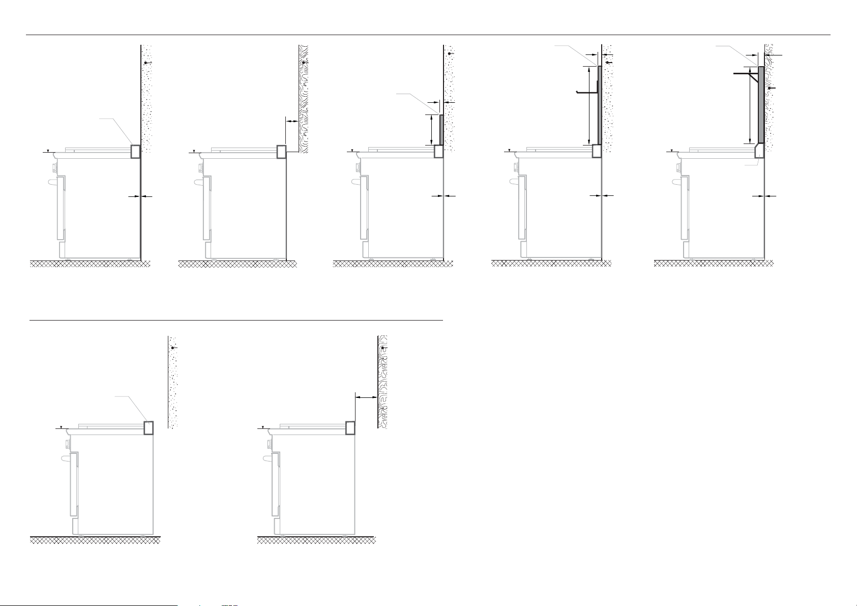
7INSTALLATION SCENARIOS AND USE OF BACKGUARDS
WALL INSTALLATION
Vent Trim
cooking
surface
0” Clearance
scenario 1
NO BACKGUARD USED
Integral Flat Vent Trim or
Angled Flat Vent Trim (
(supplied with range)
RGCV2-305 models only)
ISLAND INSTALLATION
Non-combustible
surface*
(required)
cooking
surface
scenario 2
NO BACKGUARD USED
Integral Flat Vent Trim or
Angled Flat Vent Trim (
(supplied with range)
Non-Combustible
Surface*
Min. 6” (152mm)
Clearance
RGCV2-305 models only)
Combustible
Surface
Range Mount
Low Backguard
cooking
surface
10 3/8”
(263mm)
1/2”
(13mm)
0” Clearance
scenario 3 scenario 4
RANGE MOUNT LOW BACKGUARD
(purchased separately)
Combustible
Surface
Wall Mount
cooking
surface
High Backguard
Low Shelf
(720mm)
28 3/8”
Non-combustible
surface*
(required)
0” Clearance
WALL MOUNT HIGH BACKGUARD LOW SHELF
(purchased separately)
1/2”
(13mm)
Non-combustible
surface*
(required)
cooking
surface
Wall Mount
High Backguard
High Shelf
(673mm)
Angled Vent Trim
(required)
26 1/2”
(33mm)
0” Clearance
scenario 5
WALL MOUNT HIGH BACKGUARD
HIGH SHELF AND ANGLED VENT TRIM KIT
(purchased separately)
1 5/16”
Non-combustible
surface*
or
Combustible
surface
Vent Trim
cooking
surface
scenario 6 scenario 7
NO BACKGUARD USED
Integral Flat Vent Trim or Angled Flat Vent Trim (RGCV2-305 models only)
(supplied with range)
cooking
surface
NO BACKGUARD USED
Integral Flat Vent Trim or Angled Flat Vent Trim (RGCV2-305 models only)
(supplied with range)
10
Min. 6” (152mm)
Clearance
Page 11
7INSTALLATION SCENARIOS AND USE OF BACKGUARDS
Important notes
●
All ranges come fitted standard with with an Integral Flat Vent Trim
●
There are three different backguards available for purchase:
●
Range Mount Low Backguard
●
Wall Mount High Backguard with Low Shelf
●
Wall Mount High Backguard with High Shelf, also supplied with an Angled Vent Trim.
●
For installations against non-combustible* surfaces only, you may install the range without a backguard or choose any of the three backguards.
●
For installations close to combustible surfaces (above the cooking surface), without a backguard, there must be a minimum 6” (152mm) clearance
(see Scenario 2 or 7 opposite)
●
For installations immediately against combustible surfaces (above the cooking surface), you must purchase and fit the Wall Mount High Backguard
High Shelf and Angled Vent Trim (see Scenario 5 opposite)
●
The cooking surface must sit flush or above the adjacent countertop level.
* Non-combustible surfaces:
as defined in ‘National Fuel Gas Code’ (ANSI Z223.1, Current Edition). Clearances from non-combustible materials
are not part of the ANSI Z21.1 scope and are not certified by UL. Clearances of less than 6” (152mm) must be
approved by the local codes and/or by the local authority having jurisdiction.
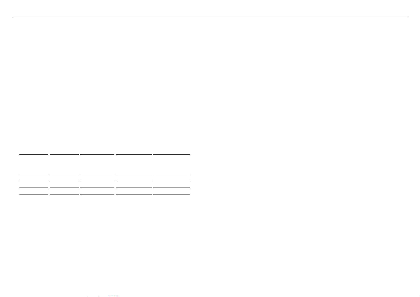
BACKGUARD MODEL NUMBERS
WALL
MOUNT HIGH
BACKGUARD
LOW SHELF
RANGE
RANGE
MOUNT LOW
BACKGUARD
30” models BGRV2-1230 BGRV2-3030 BGRV2-3030H 29 7/8” (759mm)
36” models BGRV2-1236 BGRV2-3036 BGRV2-3036H 35 7/8” (911mm)
48” models BGRV2-1248 BGRV2-3048 BGRV2-3048H 47 7/8” (1216mm)
WALL
MOUNT HIGH
BACKGUARD
HIGH SHELF
BACKGUARD
WIDTH
Note: For more information on Backguard installation, refer to the separate instructions provided with your backguard.
Backguard Installation Instructions can also be downloaded from our website, www.fisherpaykel.com
11
Page 12
8VENTILATION REQUIREMENTS
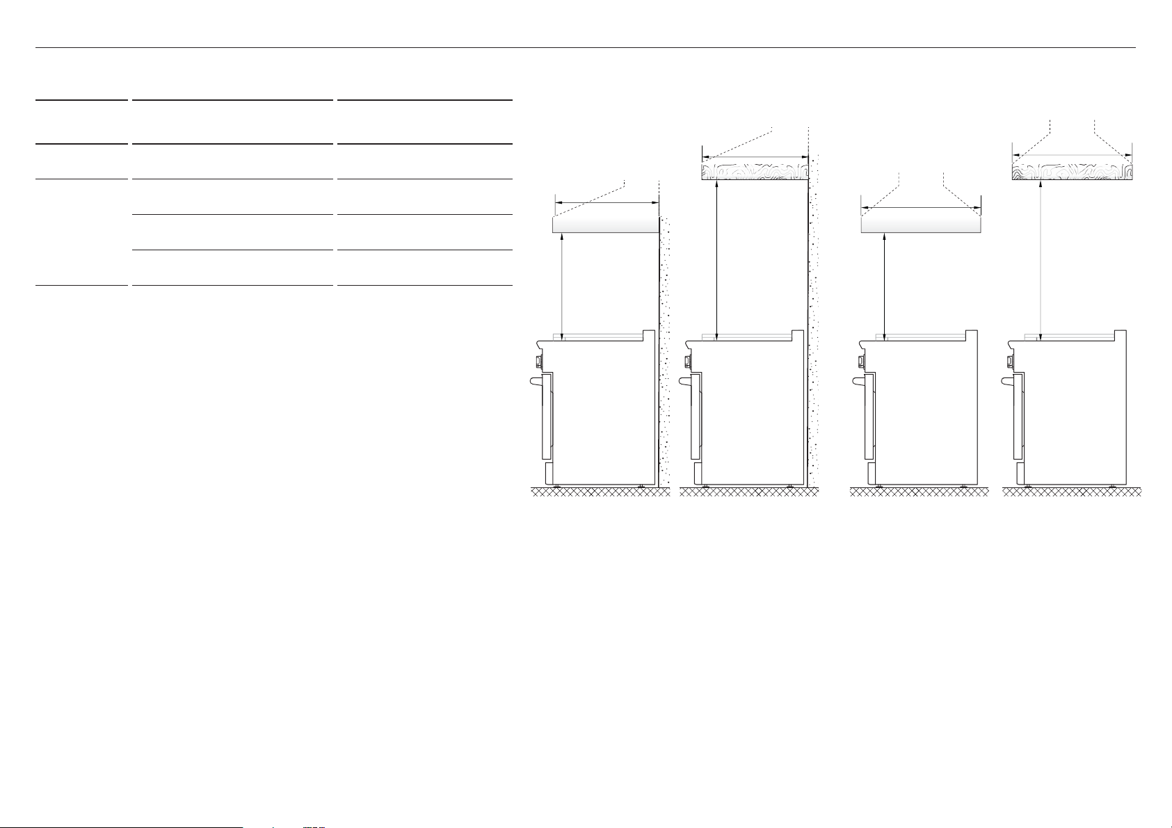
A suitable ventilation hood must be installed above the range. The following chart indicates the minimum blower capacity recommended for hood ventilation.
VENTILATION
UNIT
STANDARD WALL INSTALLATION
RECOMMENDATONS
HOOD 23” (548 mm) Deep x
Unit Width
BLOWER 48” Range
1200 CFM
36” Range
600-1200 CFM
30” Range
600 CFM
ISLAND INSTALLATION
RECOMMENDATONS
30” (762mm) Deep x
(Unit Width + 4” (102mm))
48” Range
1200 CFM
36” Range
600-1200 CFM
30” Range
600 CFM
23” (584mm)
HOOD (NON-COMBUSTIBLE)
min. 30” (762mm) max. 36” (914mm)
23” (584mm)
HOOD (inc. COMBUSTIBLE)
(for example a
wood surround)
min. 36” (914mm)
30” (762mm)
HOOD (NON-COMBUSTIBLE)
min. 30” (762mm) max. 36” (914mm)
30” (762mm)
HOOD (inc. COMBUSTIBLE)
(for example a
wood surround)
min. 36” (914mm)
Wall Installation Island Installation
Important notes
●
Ventilation hoods and blowers are designed for use with single wall ducting. However, some local building codes or inspectors may require double wall ducting and/or a damper.
Consult local building codes and/or local agencies, before starting, to ensure that hood and duct installation will meet local requirements.
●
Hood blower speeds should be variable to reduce noise and loss of heated or air conditioned household air when maximum ventilation is not required.
Normally, the maximum blower speed is only required when using the grill or the self-cleaning cycle.
●
For best smoke elimination, the lower edge of the hood should be installed a minimum of 30” (762mm) to a maximum of 36” (914mm) above the range cooking surface.
If the hood contains any combustible materials (eg a wood covering) it must be a minimum of 36” (914mm) above the cooking surface.
●
Due to a high volume of ventilation air, a source of make-up air (outside replacement air) is recommended. This is particularly important for tightly sealed and insulated homes.
A reputable heating and ventilating contractor should be consulted.
12
Page 13
9REMOVE FROM SKID & PLACE ON DOLLY
●
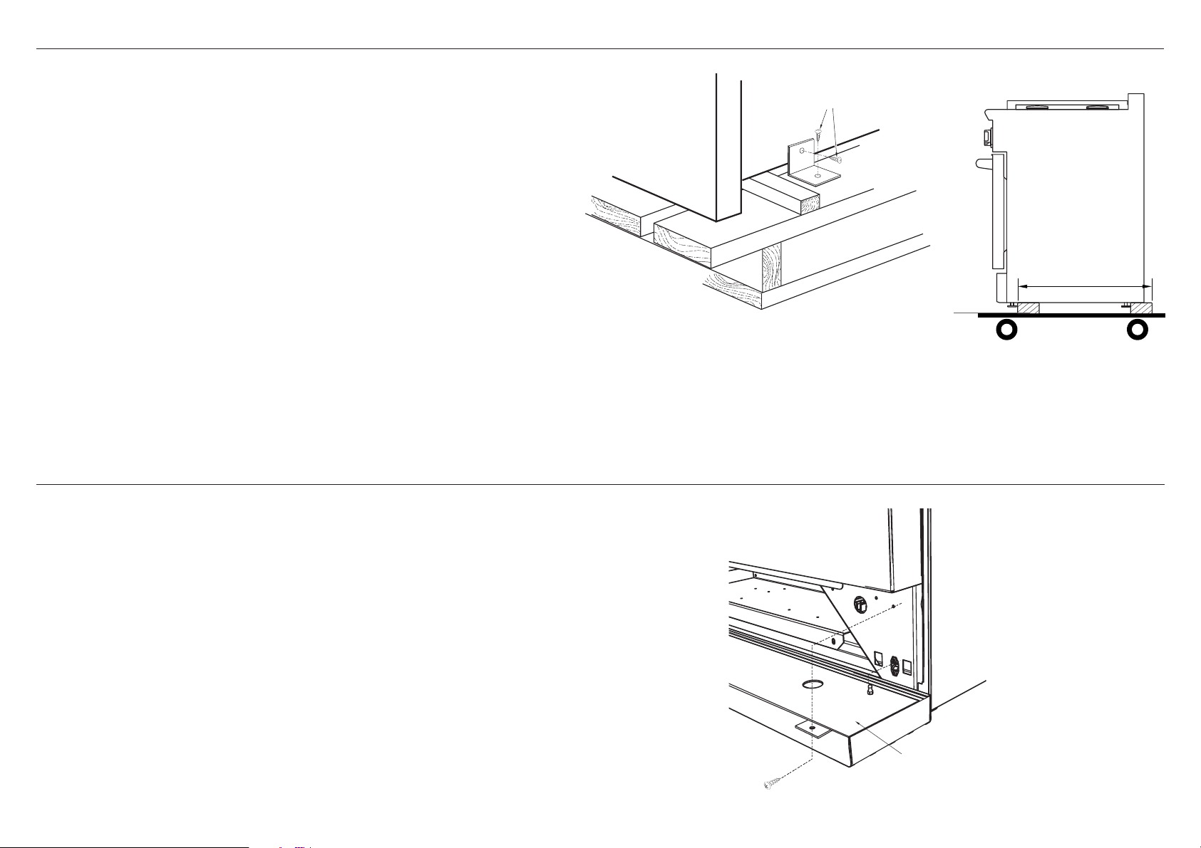
The ranges have shipping weights varying from 420 to 630lbs less approx. 50lbs after
removal of packing material. It is recommended that the oven door(s), pan supports
and front kick panel be removed to facilitate handling, reducing the weight and to pass
through some doorways:
●
With the door(s) removed, a 29 1/2” wide opening is required. Without removing the door,
a 32” wide opening is required.
●
The range is held to the skid in the front by two bolts, located behind the kickpanel; and
at the back by either two bolts (RDV2 models) located behind the rear metal panel, or
two L-brackets (RGV models) located on the bottom flange of the range back.
●
After removing the bolts and brackets, the range must be lifted and removed from the
skid.
●
Due to the weight, a dolly with soft wheels should be used to move this unit. The weight
must be supported uniformly across the bottom, as shown.
●
The range should be transported by a dolly close to its final location.
●
The floor under the legs should be protected (wood strips, carpet, paneling, etc.) before
pushing the unit back into its final position.
RGV2
model shown
Left Rear
Shipping Screws
22"
Range must
be uniformly
supported
on long braces
!0TO REMOVE AND REFIT THE KICK PANEL
To remove the kick panel
●
Remove the two screws at the top and pull forward.
To refit the kick panel
●
Replace the kick panel by reversing the procedure and securing the two screws either
side at the top.
IMPORTANT!
It is important that the two screws retaining the kick panel are secure to prevent
accidental access to live electrical components and wires.
Kick Panel (may vary)
13
Page 14
3
1
2
5
4
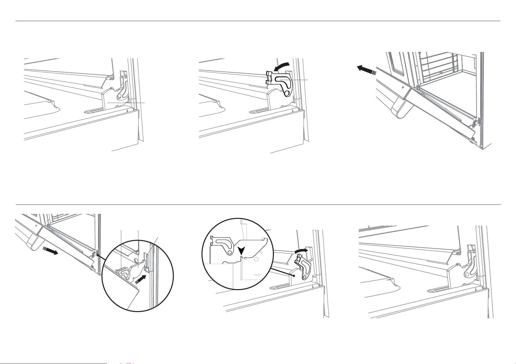
!1TO REMOVE THE OVEN DOOR(S)
IMPORTANT!
Do not lift oven door by the handle – this will cause damage.
Be sure the oven and door are cool before you begin to remove the door.
Hinge
Lock
1 Open the door completely.
Hinge
Hinge
lock
tongue
Hinge
slot
1 Position the door in an approximately halfway open position.
2 Align the hinge tongue with the hinge slots.
3 Push the door into the slots until you feel the latches locate
into position on each side.
14
2 Unlock the door hinges by rotating the lock forward.
!2TO REFIT THE OVEN DOOR(S)
4 Open the door completely and check that the hinges
are both secured by the correct notches as shown.
5 Rotate the locks into the closed position.
3 Once both hinges are unlocked, gently close the door
until approximately halfway closed. Grabbing the
sides of the door and gently lifting up and slightly
forward, the door will unlatch from the hinge.
4 Continue to lift and pull the door away from the
range.
6 Close the oven door.
IMPORTANT!
Hinge locks should rest inside the slots. Incorrect
installation will prevent door from correctly sealing.
Page 15
AA
B
C
B
A
B
D
E
C
RDV2 MODELS
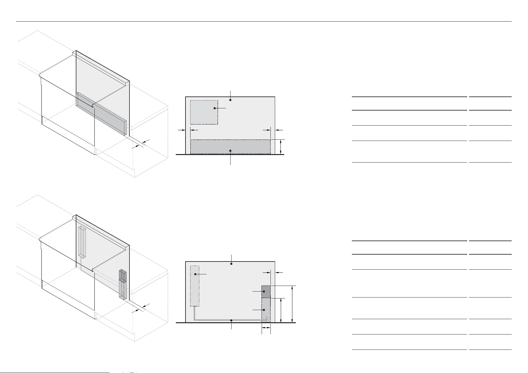
!3LOCATION OF ELECTRICAL & GAS SUPPLY
Final position of range against wall
RGV2 MODELS
REGULATOR*
ELECTRICITY AND GAS
Final position of range against wall
REGULATOR
ELECTRICITY
GAS
GAS LINE
SUPPLY AREA DIMENSIONS RDV2
Distance from either edge of range
A
to supply area
Height of gas and electrical supply
B
areas (from floor)
Depth of supply areas
C
(ie maximum protrusion of
gas connection from wall)
*Regulator location may vary depending on model
SUPPLY AREA DIMENSIONS RGV2
Distance from right edge
A
of range to supply area
Width of supply areas
B
- 30” models
- 36” models
- 48” models
Depth of supply areas
C
(ie maximum protrusion of
gas connection from wall)
Height of gas supply area
D
(from floor)
Height of electrical supply area
E
(from floor)
1 1/2” (38mm)
6” (152mm)
2” (51mm)
1 1/2” (38mm)
2” (51mm)
5” (127mm)
3” (76mm)
2” (51mm)
12” (305mm)
19” (483mm)
15
Page 16
!4ELECTRICAL CONNECTION
ALL MODELS
IMPORTANT!
●
This range must be connected to the mains
power supply only by a suitably qualified person.
●
This range must be earthed.
●
Always disconnect electric supply cord from the
wall outlet or service disconnect before servicing
this appliance.
●
Observe all governing codes and ordinances
when grounding, in absence of which, observe
Wiring diagrams
are also in the
service summary,
attached to the
inside of the kick
panel
National Electrical Code ANSI / NFPA No. 70.
RGV2 MODELS
The electrical supply must be a correctly polarized 120 VAC, 60 Hz, single phase circuit
suitable for the maximum current draw of the model, as detailed in the table below.
Verify your model’s current draw by checking the rating label on the back of the range.
MODEL
RGV2-305 5 A 15 A 60 Hz
RGV2-364GD 8 A 15 A 60 Hz
RGV2-304 5 A 15 A 60 Hz
RGV2-366 5 A 15 A 60 Hz
RGV2-488 9 A 15 A 60 Hz
RGV2-485GD 15 A 15 A 60 Hz
RGV2-486GD 12 A 15 A 60 Hz
RGV2-486GL 12 A 15 A 60 Hz
MAX.
CURRENT DRAW
CIRCUIT FREQUENCY
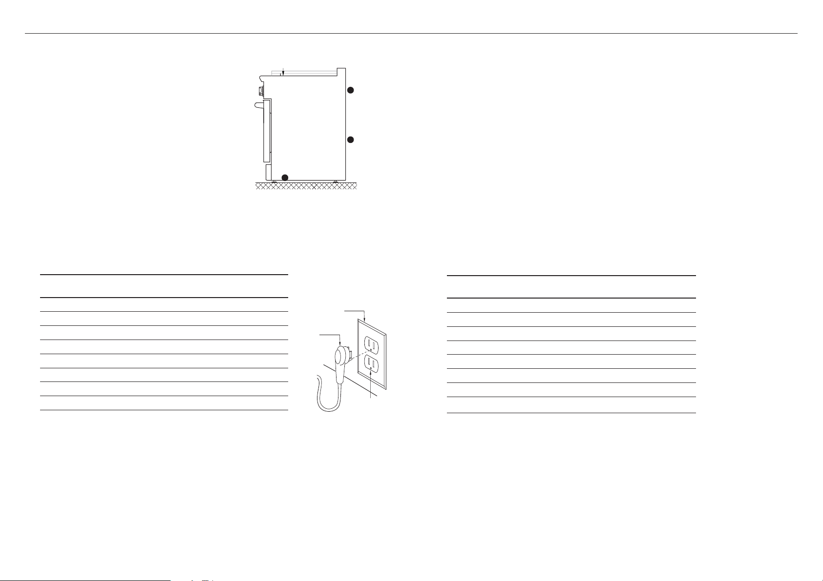
Receptacle Box
Cover Plate
Three
Prong
Plug
The rating
label is located
on the back of
the range
A wiring
diagram label
is attached to
the back of
the range
Three Prong
Receptacle
RDV2 MODELS
●
A neutral supply wire must be provided from the power source (breaker panel) because
critical range components, including the surface burner spark reignition module, require
120/240 VAC to operate safely and properly.
●
If the correct power supply circuit is not provided, it is the responsibility and obligation
of the installer and user to have proper power supply connected. This must be
accomplished in accordance with all applicable local codes and ordinances by a qualified
electrician. It is the responsibility of the installer to ensure compliance of local codes.
In the absence of local codes and ordinances, the power supply connection shall be in
accordance with the National Electric Code.
●
Observe all governing codes and ordinances when grounding. In the absence of these
codes or ordinances observe National Electrical Code ANSI/NFPA No. 70 current issue.
See the following information in this section for grounding method..
●
The ranges are to be connected to a 240/208 VAC power supply.
IMPORTANT!
An improper 120/ 240 VAC power supply will cause malfunction, damage to this
appliance, and possibly create a condition of shock hazard.
Improper connection of aluminum house wiring can result in a fire or shock hazard.
Use only connectors designed and certified for connecting to aluminum wire.
MODEL
RDV2-305 18 A 30 A 60 Hz
RDV2-304 21 A 30 A 60 Hz
RDV2-364GD 21 A 30 A 60 Hz
RDV2-366 18 A 30 A 60 Hz
RDV2-488 33 A 50 A 60 Hz
RDV2-485GD 40 A 50 A 60 Hz
RDV2-486GD 36 A 50 A 60 Hz
RDV2-486GL 36 A 50 A 60 Hz
MAX.
CURRENT DRAW
CIRCUIT FREQUENCY
Required grounding method – RGV2 MODELS
●
This appliance is factory equipped with a power supply cord with a three-prong
grounding plug (with polarized parallel blades). It must be plugged into a mating
grounding-type receptacle, connected to a correctly polarized 120 VAC. If the circuit
does not have a grounding type receptacle, it is the responsibility and obligation of the
installer to have the existing receptacle changed to a properly grounded and polarized
receptacle in accordance with all applicable local codes and ordinances by a qualified
electrician. In the absence of local codes and ordinances, the receptacle replacement
shall be in accordance with the National Electrical Code.
●
IMPORTANT!
The third prong should not, under ANY circumstances, be cut or removed.
16
Required grounding method – RGV2 MODELS
●
This appliance is factory equipped with a power supply cord with a NEMA 14-50 fourprong grounding plug. It must be plugged into a mating grounding, type receptacle,
connected to a correctly polarized 120/240 VAC. If the circuit does not have a
grounding type receptacle, it is the responsibility and obligation of the installer to
have the existing receptacle changed to a properly grounded and polarized receptacle
in accordance with all applicable local code and ordinances by a qualified electrician.
In the absence of local codes and ordinances, the receptacle replacement shall be in
accordance with the National Electrical Code.
●
IMPORTANT!
The fourth prong (round grounding pin) should not, under any circumstances, be cut
or removed.
Page 17
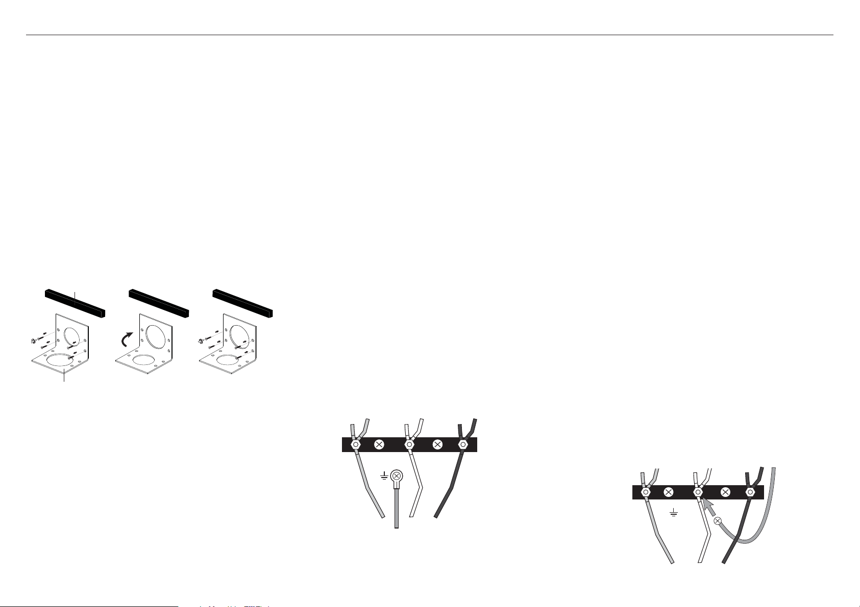
GREEN GROUND
Reconnect
here
RED WIRE
WHITE WIRE
(NEUTRAL)
BLACK WIRE
!4ELECTRICAL CONNECTION
RED WIRE
GREEN GROUND
WHITE WIRE
(NEUTRAL)
BLACK WIRE
1 2 3
RDV2 MODELS
●
Dual Fuel models must be connected to the power supply utilizing one of the following methods. For all methods of connection, the length of the cord or conduit/wiring must allow the unit
to be slid completely out of the cabinet without having to unplug or disconnect the unit from the power supply. Recommended minimum free length of cord or conduit is 4ft (1.2m). Electrical
installations and grounding must be in accordance with all local codes and ordinances, and/or the National Electric Code, as applicable.
PERMANENT CONNECTION (HARD WIRING)
●
Units may be hard wired to the power supply. The
installer must provide approved flexible steel conduit,
maximum 6ft (1.8m) long. Locate the terminal block on
the rear of the unit and remove access cover.
●
The strain relief bracket orientation must be switched
in order to accommodate for a permanent wiring
connection. This is done by the following:
1 Remove the 4 screws on the bracket.
2 Re-secure bracket with the four screws so that the
1 1/8” (29mm) smaller opening is orientated over the
opening of the back panel.
Terminal Block
Strain relief bracket
●
The conduit must be installed to the terminal block using
an approved conduit connector. The free end of the
conduit must be connected to a junction box provided in
the electrical supply zone.
●
Mount a strain relief (not provided) into the 1 1/8”
(29mm) diameter hole located below the terminal block.
Wiring for the unit is to be brought into the terminal
block through the conduit and through the strain relief.
The ends of the wiring must have 1/4” faston closed loop
lugs attached. Make suitable connections to the terminal
block provided.
●
See over for 4-wire and 3-wire connection
●
Installer — Show the owner the location of the circuit
breaker. Mark it for easy reference.
4-CONDUCTOR CORD
●
NORMALLY, A UNIT MUST BE CONNECTED TO THE
POWER SUPPLY WITH A 3-POLE, 4-CONDUCTOR CORD
KIT RATED 125/250 VOLTS, 50 AMPERES, AND MARKED
FOR USE WITH RANGES.
●
The cord kit must be attached to the range terminal block
with a strain relief which will fit a 1-3/8” (35mm) diameter
hole. If not already equipped, the cord must also have 1/4”
(6mm) faston closed-loop lugs attached to the free ends
of the individual conductors, preferably soldered in place.
1 Remove upper nuts only from the terminal block studs. Do
not remove lower nuts which secure range internal wiring
leads.
2 Mount strain relief (not provided with range) into the
1-1/2” (38mm) diameter hole in the bracket located below
the terminal block. Route wires up through strain relief.
4-Wire Connection
3 Secure the Neutral (white) power lead, to the center stud
(silver colored) of the terminal block with nut.
4 Secure the L1 (black) and L2 (red) power leads to the
outside terminal studs (brass colored) with nuts.
5 Secure the Ground (green) power lead to the back of the
range with the screw located beneath the terminal block.
6 Tighten all connections securely.
7 Reinstall the Terminal Block Cover.
3-CONDUCTOR CORD
●
WHERE LOCAL CODES AND ORDINANCES PERMIT
GROUNDING THROUGH NEUTRAL, AND CONVERSION
OF SUPPLY TO 4 WIRE IS IMPRACTICAL, UNIT MAY BE
CONNECTED TO THE POWER SUPPLY WITH A 3-POLE,
3-CONDUCTOR CORD KIT RATED 125/250 VOLTS, 50
AMPERES, AND MARKED FOR USE WITH RANGES.
The cord kit must be attached to the range back panel
with a strain relief which will fit a 1-1/2” (38mm) diameter
hole. If not already equipped, the cord must also have
1/4” (6mm) faston closed-loop lugs attached to the free
ends of the individual conductors.
1 Remove upper nuts only from the terminal block studs.
Do not remove nuts which secure range internal wiring
leads.
2 Mount strain relief (not provided with range) into the
1-1/2” (38mm) diameter hole in the bracket located below
the terminal block. Route wires up through strain relief.
3-Wire Lead Connection
3 Secure the L1 (black) and L2 (red) power leads to the
outside corresponding terminal block studs (brass
colored).
4 Secure the Neutral (white), grounded wire of the supply
circuit and reconnect one end of the mounted looped
Ground wire, located beneath terminal block, to the
center stud (silver colored) of the terminal block with nut.
5 Leave the other end of the Ground wire screwed into the
back of the range.
6 Tighten nuts securely.
7 Reinstall the Terminal Block Cover.
17
Page 18
!5GAS CONNECTION
on
Gas requirements
Verify the type of gas supplied to the location. The range is shipped from the factory set up and adjusted for Natural Gas or LP, depending on the specific model ordered.
Verify that the range is compatible with gas supply at the installation site before proceeding further. Return the range to the dealer if the unit is not set for the gas supplied at the site.
NATURAL GAS
●
Connection: 1/2” NPT Minimum 5/8” dia. flex line. Supply Pressure: 6” to 9” W.C.
LP Gas
●
Connection: 1/2” NPT Minimum 5/8” dia. flex line. Supply Pressure: 11” to 14” W.C.
●
A regulator is required at the LP source to provide a maximum pressure of 14” W.C. to the range regulator.
Requirements for hook-up to gas supply
●
The gas supply connections should be made by a qualified technician in accordance with local codes or ordinances. In the absence of a local code, the installation must conform to the latest
edition of National Fuel Gas Code ANSI Z.223.1 (Warning: this appliance must be installed by a licensed plumber or gas fitter when within the Commonwealth of Massachusetts).
●
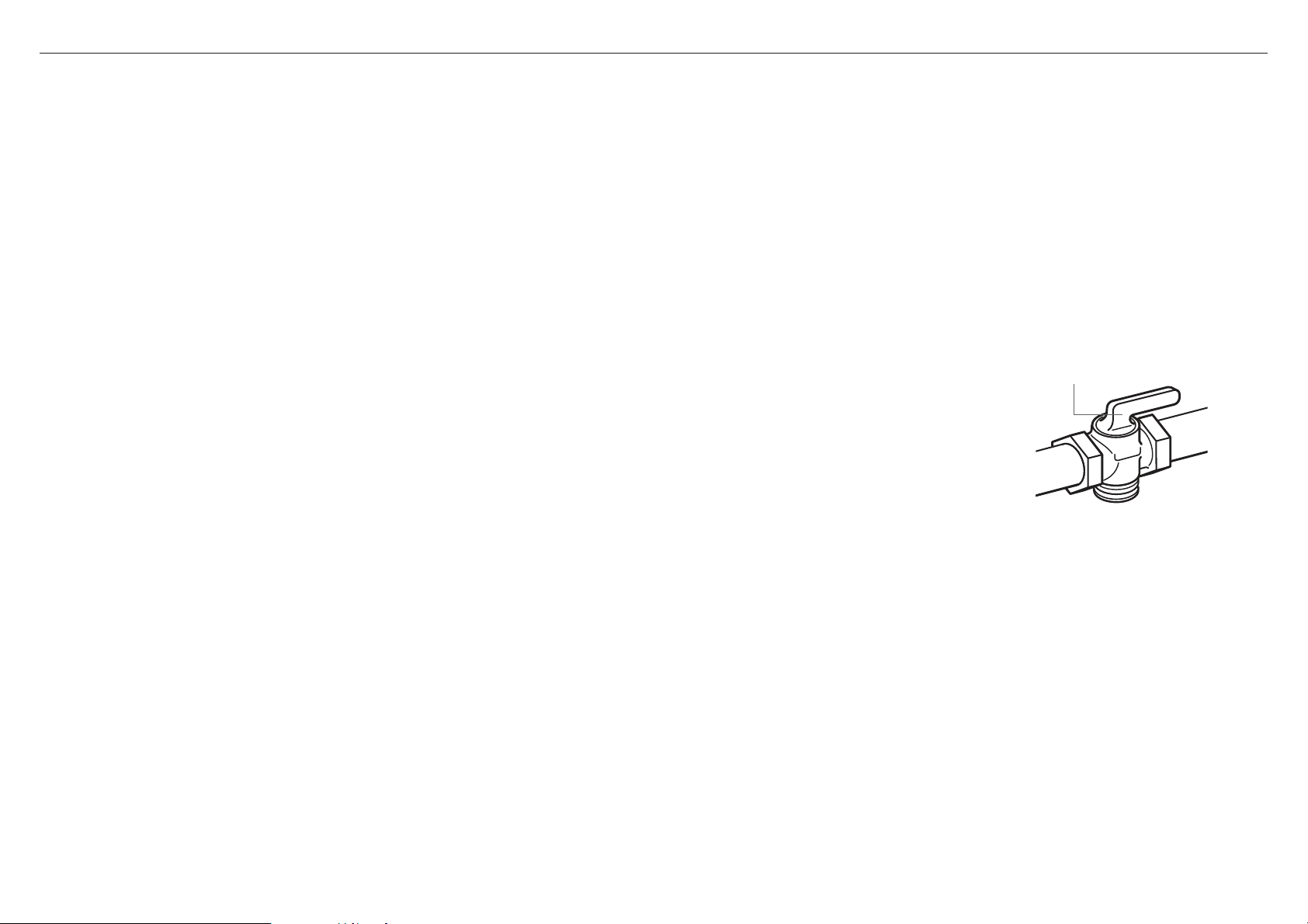
A manual shut-off valve (supplied by the installer) must be installed in an accessible location in the gas line external to the appliance for the purpose of turning on or shutting off gas to
the appliance. (In Massachusetts such shut-off valves should be approved by the Board of State Examiners of Plumbers & Gas Fitters.) The shut-off valve must be located within 6 feet
(1.8 meters) of the appliance it serves.
IMPORTANT!
Fisher & Paykel recommends installing the manual shutoff valve in a location readily accessible by the customer, so that gas to the
appliance can be shut off in an emergency situation. However, the appliance must not be modified in any way to accommodate such placement.
Installer supplied manual
shut-off valve “open” position
●
The gas supply line must not protrude beyond the back of the appliance.
●
Make sure the gas supply is turned off at the wall valve before connecting the appliance
●
Leak-testing of the appliance shall be conducted according to the manufacturer’s instructions. See instructions following.
●
The appliance must be isolated from the building’s gas supply piping system by closing its individual manual shut-off valve during any pressure
To Range
Gas supply line
testing of the gas supply piping system at test pressures equal to or less than 1/2 psig (3.5kPa.). The appliance and its individual shut-off valve must
be disconnected from the gas supply piping system during any pressure testing of the system at the test pressures in excess of 1/2 psig (3.5kPa.).
When checking the manifold gas pressure, the inlet pressure to the regulator should be at least 7.0” W.C. for natural gas or 12.0” for LP.
●
The flex line for the gas supply must be metal and be approved for appliance use by a certifying agency (CSA, CGA, or UL).
Never use a hose made of rubber or other synthetic material, as the heat may cause the hose to melt and develop leaks.
●
When hooking up the gas supply from the wall hard pipe to the range hard pipe, installation length of flex line between range/wall hard piping must accommodate range being pulled from wall
for cleaning or servicing purposes. When range is pulled from wall, no strain should occur at range or wall hard pipe connections.
18
Page 19
!6LEAK TESTING
●
Make sure all oven and burner knobs are set to OFF before connecting range to gas supply.
●
After final gas connection is made, turn gas supply on and test all connections in gas supply piping for gas leaks with a soapy water solution.
●
In order to avoid property damage or serious personal injury, never use a Iighted match or open flame.
If a leak is present, tighten joint or unscrew, apply more joint compound, tighten again and retest connection for leak.
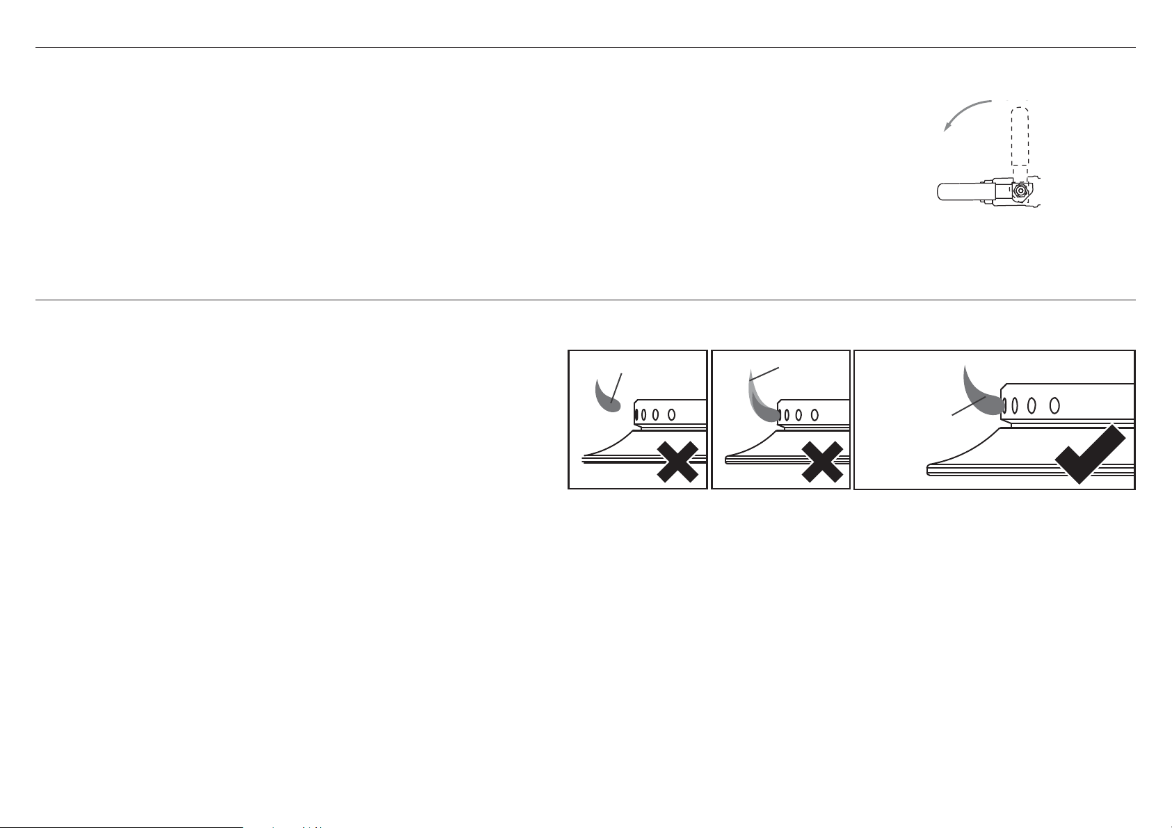
!7COOKTOP BURNERS
Cooktop burners
●
To check that the ignition system operates correctly, light each burner by itself,
then all burners in combination.
●
Check for a well-defined blue flame without any yellow tipping.
●
If any abnormality is evident, check that the components of the burner assembly
are located properly.
●
When installing the burner port ring, align the two locating pins in the bottom side
of the port ring with the locating notch and center holes on the top side of the
simmer ring, and make sure these are properly engaged. Important! Incorrect installation
may produce a potentially dangerous flame and result in poor burner performance.
●
No air shutter adjustment is possible on the cooktop burners.
Proper operation is achieved with factory installed settings for the correct gas type.
●
If proper operation cannot be obtained, contact Customer Care or your nearest
Fisher & Paykel Authorized Service Center.
●
The range and cooktop must not be used by the customer until proper operation
has been achieved.
Lifting off
Yellow tip
ON
ON
Good flame
GAS
GAS
19
Page 20
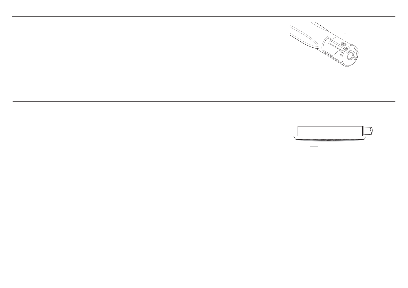
!8GRILL AND GRIDDLE BURNERS (SOME MODELS ONLY)
●
Each valve and air shutter is individually tested and adjusted prior to shipment. Normally adjustment is not required, however,
vibration during transit, gas conversion or variations in the local gas supply may make minor adjustments necessary.
●
Check for the proper burner flame characteristics and adjust air shutters if necessary.
Burner flames should be blue and stable with no yellow tips, excessive noise or lifting of the flame from the burner.
If any of these conditions exist, check that the air shutter or burner ports are not blocked.
If this condition persists, adjust the air shutter as required.
If the flame is too yellow, indicating insufficient air, open the shutter to increase air inlet.
If the flame is noisy or tends to lift away from
the burner, indicating too much air, close the shutter to reduce air.
!9INFRARED BROIL AND OVEN BAKE BURNERS (RGV2 MODELS ONLY)
●
The oven infrared broiler burner has no air shutter and is not adjustable.
●
It is necessary to operate the oven broiler for 20-30 minutes to eliminate the harsh odor of the insulation binder.
This must be done before using the range for the first time and with proper ventilation.
●
The oven bake burner has an air shutter and is adjustable.
●
Check for the proper burner flame characteristics. Burner flames should be blue and stable with no yellow tips, excessive
noise or lifting of the flame from the burner. If any of these conditions exist, check that the air shutter (oven burner only) or
burner ports are not blocked. If this condition persists, adjust the air shutter as required. If the flame is too yellow, indicating
insufficient air, open the shutter to increase air inlet. If the flame is noisy or tends to lift away from the burner, indicating too
much air, close the shutter to reduce air.
●
After approximately 5-8 minutes of operation the burner screen should be glowing red.
Blue flame
Air shutter
Infrared broil burner
IMPORTANT!
For warranty coverage, Fisher & Paykel requires that all burner adjustments be made by a qualified technician at the time
of installation. IMPROPER ADJUSTMENT WILL VOID YOUR WARRANTY.
20
Page 21
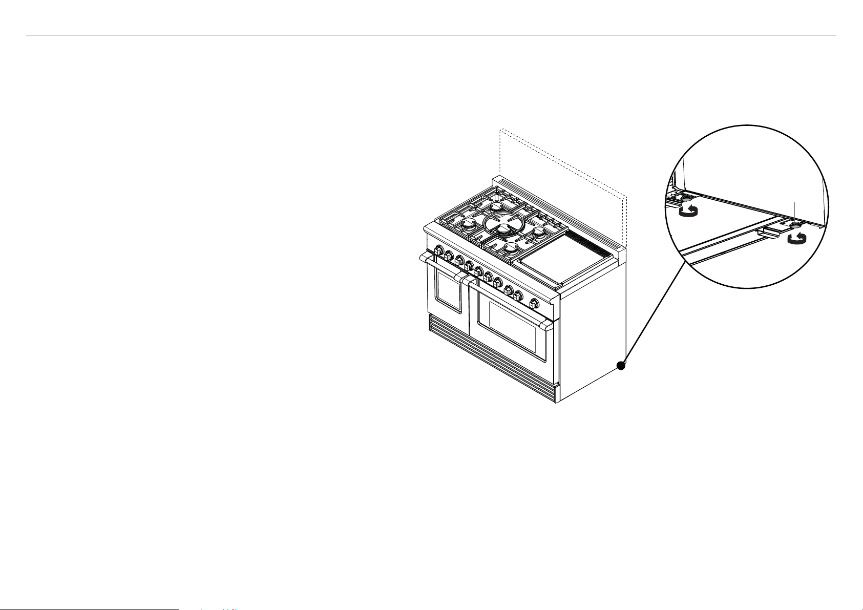
@0MOVING RANGE INTO POSITION
Prior to final positioning
●
Ensure the doors and kick panel are securely in place, if removed previously.
●
Ensure any backguard is fitted prior to final positioning.
●
Ensure all electrical and gas connections have been done as per instructions.
●
Ensure flooring and adjacent cabinetry are also level. To achieve a flush fit of
the range to adjoining countertops, it will be necessary to have level cabinets
(front to back, and left to right across opening of the range).
1 The range should be level, left to right and front to back.
Level the range prior to final positioning by adjusiting the front and rear leveling
feet, as shown. First adjust the rear feet to align the rear of the range with the rear
corners of the adjacent cabinetry.
Note: The rear leveling feet are not accessible once the range is pushed into place.
1 Once the range is in place, the front leveling feet can be accessed to level the
front of the range.
Ensure any backguard
is fitted prior to final
positioning.
Leveling foot
Level the range prior to final
positioning by adjusiting the front
and rear leveling feet
Range may vary
21
Page 22
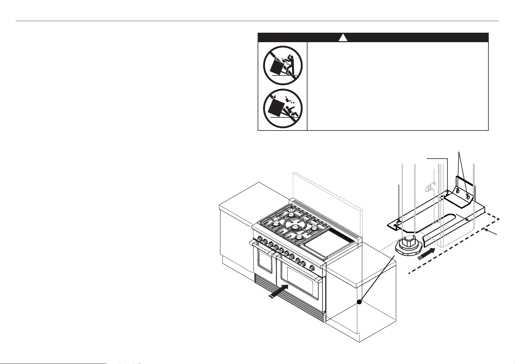
@1INSTALLING THE ANTI-TIP BRACKET
All ranges must have an anti-tip device correctly installed as per the following
instructions. If you pull the range out from the wall for any reason, make sure
that the device is properly engaged when you push the range back against
the wall. If it is not, there is a risk of the range tipping over and causing injury
if you or a child stand, sit or lean on an open oven door.
Included Parts
(4) #10 x 2” wood screws, (2) 5/16 x 1 -1/2” sleeve anchors, (2) lag bolts and
washers and (1) Anti-tip bracket
Installing the bracket
Instructions are provided for wood and concrete floors. Any other type of
construction may require special installation techniques as deemed necessary
to provide adequate fastening of the Anti-tip bracket to the floor and wall.
The use of this bracket does not preclude tipping of the range when not
properly installed.
Wood substrate
1 Place the bracket against the back wall, into the right rear corner where
the range is to be located. Leave a gap between the wall (or side of range)
and the bracket, as shown.
2 Drill (x2) 1/8” diameter pilot holes in the center of the small holes.
A nail or awl may be used if a drill is not available.
3 Fasten the bracket securely to the floor and wall.
Concrete or cement substrate
1 Locate the bracket as shown.
2 Using the bracket as a template, drill (x2) 5/16” diameter pilot holes
in the center of the larger holes to a depth of at least 1 3/4”.
3 Place the sleeve anchors into the holes and use a hammer to tap them
all the way in.
4 Tighten the nuts on the sleeve anchors to fasten the bracket securely
to the floor.
!
WARNING!
To reduce the risk of tipping the appliance, the appliance must
be secured by properly installed anti-tip device packed with the
appliance.
●
A child or adult can tip the range and be killed.
●
Install the anti-tip device to the structure by fastening
the supplied bracket to the floor and wall following the
instructions for installing the anti-tip device.
●
Engage the anti-tip device.
●
Re-engage the anti-tip device if the range is moved.
●
See installation instructions for details.
Failure to do so can result in death or serious burns to children
of adults.
(2) Wood Screws into Back
Wall (ALL Installations)
(2) Small Holes for
Wood Installations
(2) Large Holes for
Concrete Installations
Back wall
1/2”
(13mm)
Once Installed
Check for proper installation of the range and Anti-tip bracket by
grasping the back of the range and carefully attempt to tilt it forward.
22
Right side of
wall or range
Range may vary
Page 23
@2 FINAL CHECKLIST
TO BE COMPLETED BY THE INSTALLER
GENERAL
Placement of unit.
Specified clearance maintained to cabinet surfaces.
Unit Level – front to back, side to side.
All packaging material and tie straps removed.
Backguard attached if there is less than 6” (152mm) clearance to combustibles behind unit.
Radiant tray placed in grill unit (if equipped). The grill grate is in place.
Door is correctly installed. Check hinge locks both rest inside slots comfortably and neither
of the locating notches are visible when oven door is open. When oven door is closed it
should run parallel to surrounding cabinetry and sit completely vertical to ensure oven is
sealing correctly.
GAS SUPPLY
Connection: 1/2 NPT with a minimum 5/8” diameter flex line. Site gas supply is compatible
with range model, and sufficient pressure is available (see section ‘Gas connection’).
The pressure regulator which is connected to the manifold is set for 5.0” W.C. for natural
gas or 10.0” W.C. for LP.
Manual gas shut-off valve installed in an accessible location.
Unit tested and free of gas leaks.
ELECTRICAL
Receptacle with properly rated over-current protection is provided for service cord
connection.
Adequate ground connection.
Front kick panel in place and two screws secure.
OPERATION
All internal packing materials removed. Check below the grate and inside the oven.
If used on LP gas, verify that pressure regulator, orifice hoods, air shutters, and
valve have been set for use with LP gas.
Grill grate is seated and does not rock (if equipped).
Knobs turn correctly and freely.
Each burner lights satisfactorily, both individually and with other burners operating
at the same time.
Flame adjustment made on air shutter of each oven, griddle, or grill burner.
Griddle is level and does not rock (if equipped).
Oven door hinges seated and door opens and closes properly.
Burner pan supports correctly positioned, level, and do not rock.
Griddle flame correct.
Grill flame correct.
Cooktop burner flame correct.
Complete and keep for safe reference:
Model
Serial No.
Purchase Date
Purchaser
Dealer Address
Installer’s Name
Installer’s Signature
Installation Company
Installation Date
23
Page 24

 Loading...