

Fisher & Paykel RB90S64MKIW, RB36S25MKIW Service Manual
840653
Service Manual
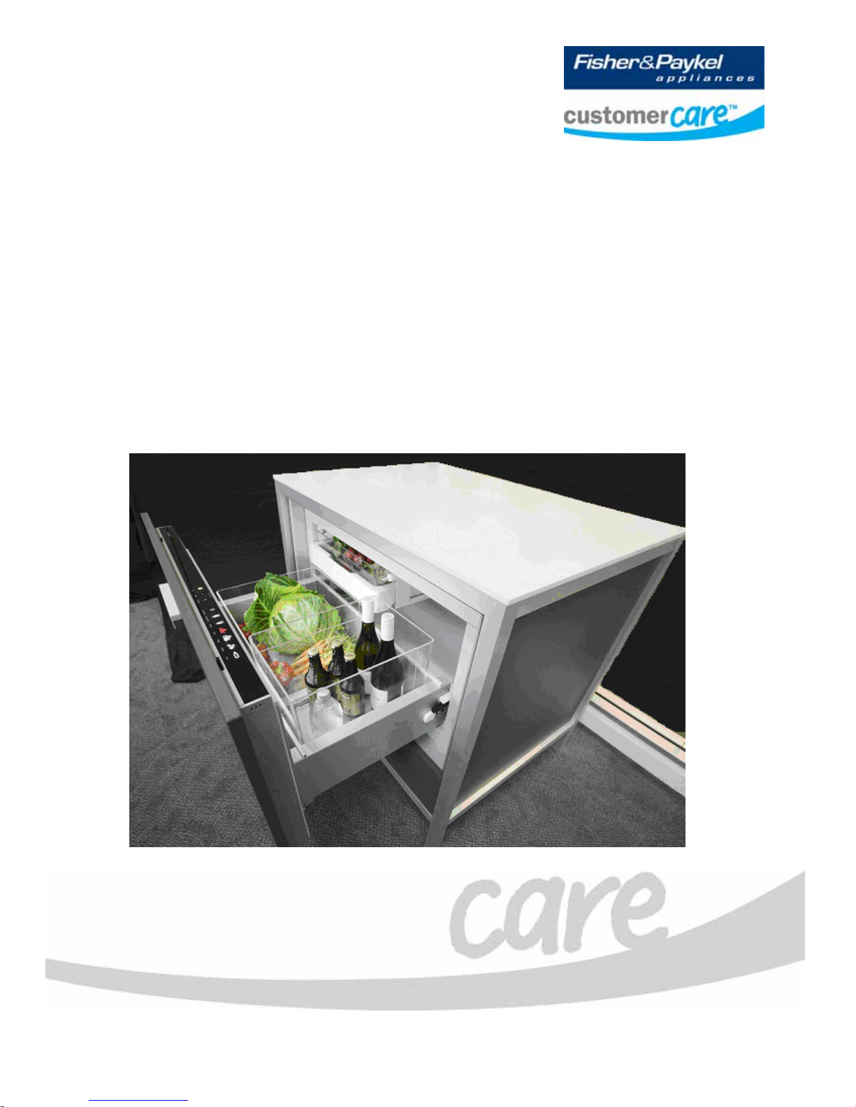
CoolDrawer
Models:
RB36S25MKIW
RB90S64MKIW

840653 - APRIL 2008 REPRINT - APRIL 2009
Fisher & Paykel Appliances Ltd
78 Springs Road,
East Tamaki,
PO Box 58-732, Greenmount,
Auckland,
New Zealand
Phone: 09 273 0600
Fax: 09 273 0656
Email: customer.care@fp.co.nz
Fisher & Paykel Customer Services Pty Ltd
PO Box 798, Cleveland, QLD 4163
A.C.N. 003 3335 171
19 Enterprise Street
Cleveland, QLD 4163
Australia
Telephone: (07) 3826 9100
Facsimile: (07) 3826 9164
E-mail: customer.care@fp.com.au
Fisher & Paykel Appliances Ltd U.K
Maidstone Road
Kingston
Milton Keynes
Buckinghamshire
MK10 0BD
England
Telephone: 0845 066 2200
Facsimile: 0845 331 2360
E-mail:
customer.care@fisherpaykel.co.uk
Fisher & Paykel Appliances
Unit D2
North Dublin Corporate Park
Swords
Co Dublin
Ireland
Telephone: 1800 625 174
Facsimile: 1800 635 012
E-mail: customer.care@fisherpaykel.ie
Fisher & Paykel Appliances Inc
5900 Skylab Rd,
Huntington Beach
California, CA92647
USA
Telephone: 888 936 7872
E-mail: customer.care@fisherpaykel.com
COPYRIGHT © FISHER & PAYKEL LTD 2008 - ALL RIGHTS RESERVED
2
The specifications and servicing procedures outlined in this manual are subject to change without notice.
The latest version is indicated by the reprint date and replaces any earlier editions.

840653
3
CONTENTS
1 SPECIFICATIONS .....................................................................................................................................6
1.1 Cabinet Specifications........................................................................................................................6
1.2 Compressor Specification ..................................................................................................................6
1.3 Serial Plate Location...........................................................................................................................6
2 THEORY OF OPERATION........................................................................................................................7
3 INSTALLATION INSTRUCTIONS.............................................................................................................8
3.1 Product Dimensions ...........................................................................................................................9
3.2 Cabinetry Dimensions ......................................................................................................................10
3.3 Parts Supplied ..................................................................................................................................11
3.4 Integrated Panel Preparation ...........................................................................................................12
3.4.1 Integrated Panel Material .........................................................................................................13
3.4.2 Height Of Drawer Panel............................................................................................................13
3.4.3 Height Of False Panel ..............................................................................................................13
3.5 Create Cut-Outs In Frame................................................................................................................ 14
3.6 Locate And Secure Install Brackets .................................................................................................14
3.7 Attach Inlet And Outlet Vent Ducts...................................................................................................15
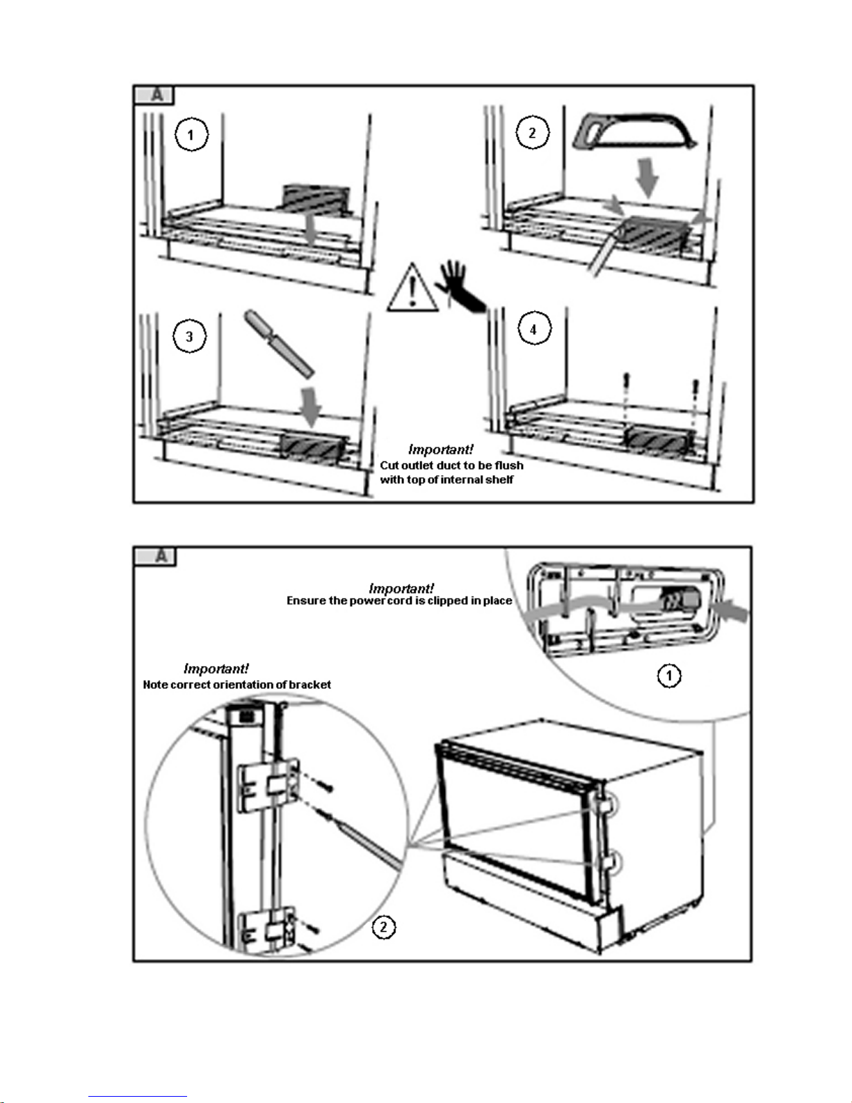
3.8 Attach Power Cord And Trim Brackets.............................................................................................15
3.9 Move Product Into Cavity .................................................................................................................16
3.10 Fit Drawer Panel Attachment Hooks ..............................................................................................16
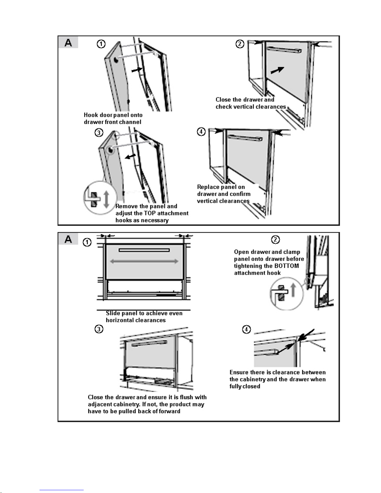
3.11 Attach Drawer Panel To Front Of Drawer ......................................................................................17
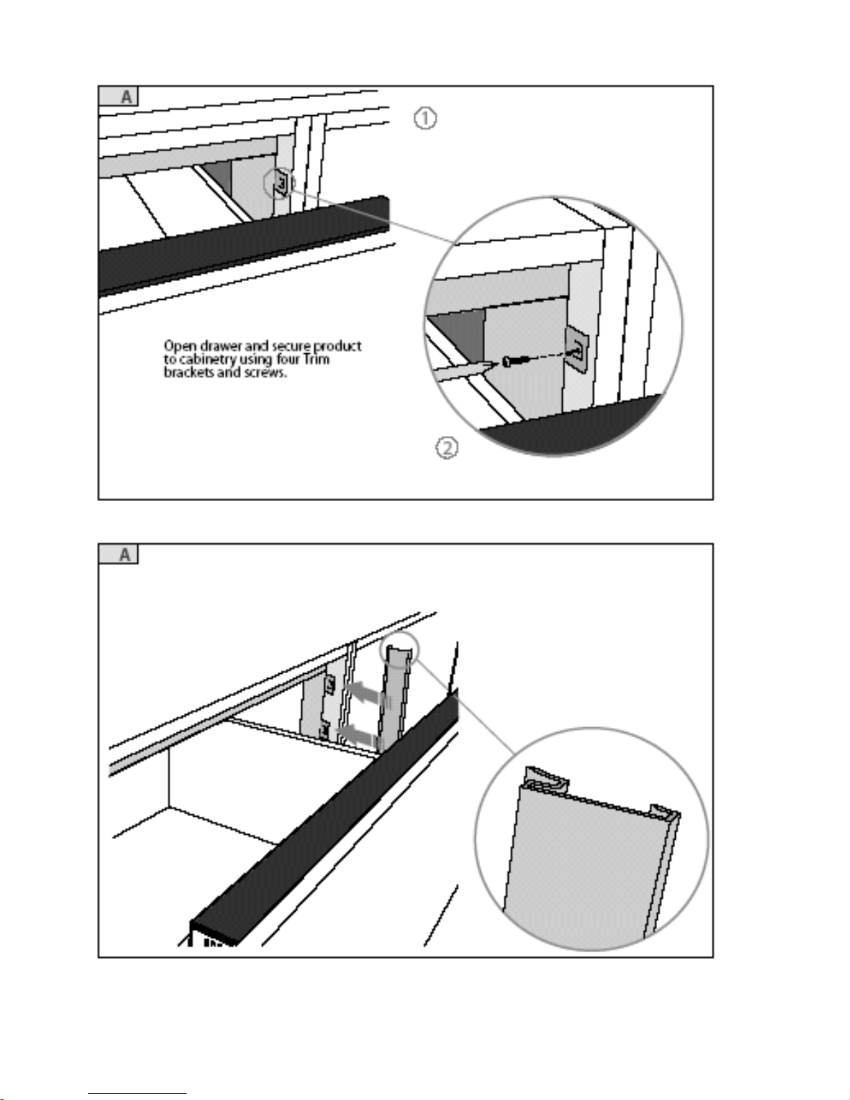
3.12 Secure Trim Brackets To Cabinetry ............................................................................................... 18
3.13 Attach Trims To Sides Of Cabinetry...............................................................................................18
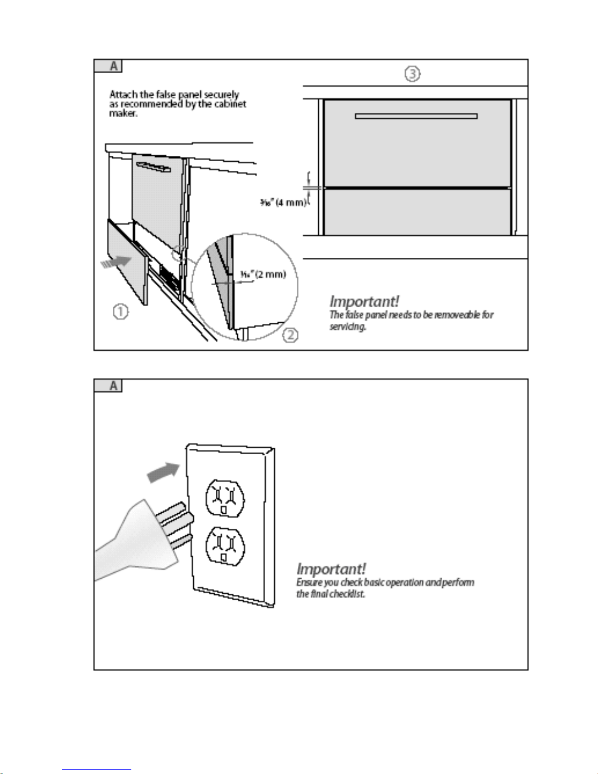
3.14 Attach False Panel .........................................................................................................................19
3.15 Check Operation.............................................................................................................................19
4 USING ALTERNATE ENERGY GENERATION......................................................................................20
4.1 Product Facts ...................................................................................................................................20
4.2 Using A Battery Driven Inverter Supply............................................................................................20
4.3 Using A Motor Driven Generator Supply.......................................................................................... 21
4.4 Summary ..........................................................................................................................................21
5 USER OPTIONS ......................................................................................................................................22
5.1 User Interface Display ......................................................................................................................22
5.1.1 Lock ..........................................................................................................................................23
5.1.2 Mode Select..............................................................................................................................23
5.1.3 Temperature Adjustment ..........................................................................................................23
5.1.4 Special Options Mode ..............................................................................................................23
5.1.5 Control Panel Beeps.................................................................................................................24
5.1.6 Fault Alarm ...............................................................................................................................24
5.1.7 User Modes ..............................................................................................................................24
5.1.7.1 Freezer Mode (-18
O
C / 0
O
F) .................................................................................................24
5.1.7.2 Chill Mode (-0.5
O
C / 31
O
F)....................................................................................................24
5.1.7.3 Fridge Mode (3
O
C / 37
O
F).....................................................................................................25
5.1.7.4 Pantry Mode (12
O
C / 54
O
F) ..................................................................................................25
5.1.7.5 Wine Mode (7 to 15
O
C / 45 to 59
O
F) ....................................................................................25
5.1.8 Function Select.........................................................................................................................26
5.1.8.1 Bottle Chill Mode...................................................................................................................26
5.1.8.2 Fast Freeze Mode ................................................................................................................26
5.1.8.3 Deep Freeze Mode (-25
O
C / -13
O
F) .....................................................................................26
6 THE REFRIGERATION CIRCUIT............................................................................................................27
7 COMPONENTS........................................................................................................................................28
7.1 Cabinet .............................................................................................................................................28
7.2 Evaporator Fan.................................................................................................................................28
7.3 Condenser Fan.................................................................................................................................28
7.4 Evaporator........................................................................................................................................28
7.5 Suction & Capillary Line ...................................................................................................................28
7.6 Power/Control Module...................................................................................................................... 28
7.7 Cabinet Module ................................................................................................................................28
7.8 Drawer Reed Switch.........................................................................................................................28
7.9 Cabinet Sensors...............................................................................................................................28
7.10 Filter Drier.......................................................................................................................................29

840653
4
7.11 Water Evaporation Tray..................................................................................................................30
8 ELECTRONICS SECTION...................................................................................................................... 31
8.1 Overview Function Description.........................................................................................................31
8.1.1 Electronic Functional Schematic.............................................................................................. 31
8.1.2 Control & Peripheral Functions................................................................................................ 31
8.1.2 Control & Peripheral Functions................................................................................................ 32
8.1.3 Power/Control Module ............................................................................................................. 32
8.1.4 Cabinet Module........................................................................................................................ 33
8.1.5 Display Module/User Interface................................................................................................. 33
8.1.6 Defrost Heater.......................................................................................................................... 33
8.1.6.1 Thermal Fuse....................................................................................................................... 33
8.1.7 Auxiliary Heater Element ......................................................................................................... 34
8.1.8 Condensor Fan ........................................................................................................................ 34
8.1.9 Evaporator Fan ........................................................................................................................ 34
8.1.10 Interior LED Lights ................................................................................................................... 35
8.1.11 Speaker.................................................................................................................................... 35
8.1.12 Wiring Harness Air Bell............................................................................................................ 35
8.1.13 Reed Switch............................................................................................................................. 36
8.1.14 Thermistor Temperature Sensors............................................................................................ 36
9 COMPRESSOR....................................................................................................................................... 37
9.1 Variable Capacity Compressor Control Overview............................................................................37
9.2 Built-In Electronic Protections (Within The Module/Inverter)............................................................37
9.2.1 Compressor Start-Up............................................................................................................... 37
9.2.2 Overload Detection And Protection ......................................................................................... 37
9.2.3 Compressor Overload.............................................................................................................. 37
9.2.4 Power Limitation (Temperature Protection)............................................................................. 37
9.2.5 Short Circuit Protection............................................................................................................ 37
9.3 Fault Finding .....................................................................................................................................38
9.3.1 Quick Guide To Fault Finding With VC Compressors ............................................................. 38
9.3.2 Compressor Fault Diagnosis ................................................................................................... 39
9.3.2.1 Compressor Won't Start - Dead........................................................................................... 39
10 FAULT FINDING PROCEDURE......................................................................................................... 40
10.1 Fault Display Codes (Both Visual And Audible) .............................................................................40
10.1.1 Binary Code ............................................................................................................................. 40
10.1.2 Fault Codes.............................................................................................................................. 40
10.1.3 Diagnostic Mode ...................................................................................................................... 42
10.1.4 Diagnostic Mode LEDs ............................................................................................................ 43
10.1.4.1 Compartment Sensor Temperature ................................................................................. 44
10.1.4.2 Lower Sensor Temperature ............................................................................................. 44
10.1.4.3 Evaporator Inlet Sensor Temperature ............................................................................. 45
10.1.4.4 Evaporator Outlet Sensor Temperature .......................................................................... 45
10.1.4.5 Defrost Sensor Temperature ........................................................................................... 45
10.1.4.6 Filter Sensor Temperature............................................................................................... 46
10.1.4.7 Input Status...................................................................................................................... 46
10.1.4.8 Output Status ................................................................................................................... 46
10.1.4.9 Last Fault ......................................................................................................................... 47
10.1.5 Sensor Temperature Conversion ............................................................................................ 47
10.1.6 Temperature Conversion Chart ............................................................................................... 48
10.1.7 Data Download ........................................................................................................................ 49
10.2 To Manually Force A Defrost..........................................................................................................49
10.3 Defrost Cycle ..................................................................................................................................50
10.4 Show Room Mode ..........................................................................................................................51
10.5 Special Options Mode.....................................................................................................................51
10.6 Control Panel Beeps.......................................................................................................................52
11 WIRING DIAGRAMS........................................................................................................................... 53
12 SERVICING PROCEDURES............................................................................................................... 55
12.1 Considerations................................................................................................................................55
12.2 Electrical Safety Test......................................................................................................................55
12.3 Component Replacement...............................................................................................................56
12.3.1 Removal Of Drawer Gaskets................................................................................................... 56
12.3.2 Replacement Of Interior Lamps............................................................................................... 57
12.3.3 Removal Of Drawer Tray ......................................................................................................... 57

840653
5
12.3.4 Removal Of Decorative Front Panel.........................................................................................57
12.3.5 Removal Of Lower Front Access Panel ...................................................................................58
12.3.6 Removal Of Front Chassis Cover.............................................................................................58
12.3.7 Removal Of Display Module/User Interface .............................................................................58
12.3.8 Removal Of Drawer Front Panel ..............................................................................................58
12.3.9 Drawer Front Tilt Adjustment....................................................................................................59
12.3.10 Removal Of Anti Racking Bar...................................................................................................60
12.3.11 Removal Of Drawer Slide .........................................................................................................61
12.3.12 Removal of Small Upper Tray ..................................................................................................63
12.3.13 Removal Of Humidity Tray Slide ..............................................................................................63
12.3.14 Removal Of Drawer Harness ...................................................................................................63
12.3.15 Removal Of Condenser Fan.....................................................................................................65
12.3.16 Removal Of Power/Control Module..........................................................................................65
12.3.17 To Gain Access To Evaporator Area........................................................................................65
12.3.18 Removal Of Rear Duct Cover...................................................................................................66
12.3.19 Replacement Of Defrost Sensor ..............................................................................................67
12.3.20 Replacement Of Evaporator Inlet Sensor.................................................................................67
12.3.21 Replacement Of Evaporator Outlet Sensor..............................................................................67
12.3.22 Replacement Of Filter Sensor ..................................................................................................68
12.3.23 Replacement Of Compartment Sensor ....................................................................................68
12.3.24 Removal And Refitment Of Air Bell ..........................................................................................68
12.3.25 Removal Of Humidity Lid Control .............................................................................................69
12.3.26 Removal Of Evaporator Fan Motor ..........................................................................................69
12.3.27 Removal Of Defrost Heating Element ......................................................................................70
12.3.28 Removal Of Auxiliary Heater Element......................................................................................70
12.3.29 Replacement Of Evaporator.....................................................................................................70
12.3.30 Replacement Of Compressor...................................................................................................71
12.4 Compartment Spills And Clean Up Procedure...............................................................................71
12.5 Block/Edge Connectors..................................................................................................................72
12.6 Special Tools..................................................................................................................................74
12.6.1 Data Down Load Pen ...............................................................................................................74
12.6.1.1 Notes on Data Downloading.............................................................................................74
12.7 Pressure Testing Of The Refrigeration System .............................................................................75
12.7.1 How To Use The In-Line Pressure Gauge ...............................................................................75
12.8 Transporting Of The CoolDrawer ...................................................................................................76
840653
6
1 SPECIFICATIONS
1.1 Cabinet Specifications
DIMENSIONS
Height 638 mm (251/8”)
Depth 550 mm (2143/64”)
Width 855 mm (3343/64”)
Compartment Capacity 123 litres (3.1 cu.ft.)
Refrigeration Class T
Evaporator Defrost Element
RB90S64 230 volts AC
RB36S25 115 volts AC
200 Watts 264 Ohms
200 Watts 66 Ohms
Condenser Fan 12 volts DC
Auxiliary Heater
RB90S64 230 volts AC
RB36S25 115 volts AC
15 Watts 3527 Ohms
15 Watts 882 Ohms
1.2 Compressor Specification
Make/type Matsushita VCC Low Back Pressure
Model ENI57C13DGH
Volts 240 DC
Input Watts 104 watts
Output Watts 173 watts
Nominal BTU 591Btu/h
Motor Run Current 0.30 amps
Winding Resistance U-W
U-V
V-W
8.44 ohms
8.44 ohms
8.44 ohms
Motor Overload Protector MM3-71CC
Refrigerant Type R134a
Gas charge R134a 85g
Oil Charge cm3 215
Inverter Board 3 Phase Full Bridge PWM Inverter
Input voltage for inverter board 220V 50Hz AC
Inverter input current 1.00 amp
1.3 Serial Plate Location
The serial plate is located inside the cabinet in the top right-hand front corner.

840653
7
2 THEORY OF OPERATION
The CoolDrawer is a refrigerated drawer with a wide operating temperature range of between +15 and
–25
O
C, (59 and -13OF) having five different operation modes of a freezer, chiller, fridge, pantry and even to a
wine cooler. The system has a horizontally mounted evaporator in the floor of the cabinet, where the cold air
is drawn through the evaporator by the evaporator fan, and then passes into the ducted back wall to enter
the cabinet higher up.
It has a fan forced condenser system utilizing the benefits of electronic temperature control and has a
variable speed compressor (VCC).
For service access into the CoolDrawer, refer to the servicing procedures (Section
12).
Removal of the complete drawer is carried out by the removal of the side trims (refer to Sections
3.12 and
3.13).
Access to the main power controller is gained by the removal of the lower front panel.
840653
8
3 INSTALLATION INSTRUCTIONS
For further information regarding the installation of the product, refer to the copy of the Installation
Instructions supplied with it.
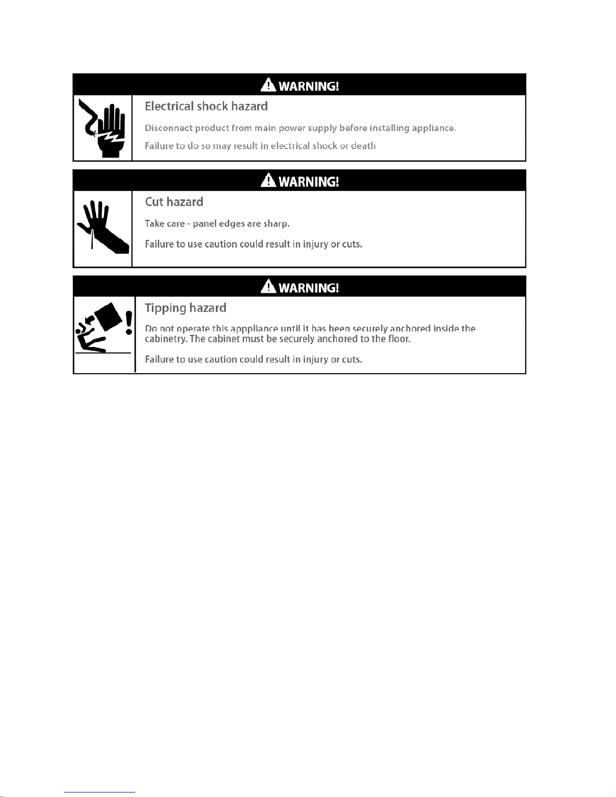
The CoolDrawer MUST be installed to allow for future removal from the enclosure if service is required. Do
not seal this CoolDrawer into the cabinetry with silicone or glue. Doing so will make future servicing difficult.
Fisher & Paykel will not be liable for any costs associated with removing or replacing a sealed-in product, nor for
repairing any damage that may be incurred by doing this.
Care should be taken when the appliance is installed or removed to reduce the likelihood of damage to the
power supply cord.
Failure to install the CoolDrawer correctly will invalidate any warranty or liability claims.
If the power supply cord is damaged, it must be replaced. Parts are available from an Authorised Fisher &
Paykel dealer.
Cabinetry must be sufficiently robust to support a combined product and food load of 100 kg (220 lb). Bearers
may be required to support the internal shelf.
Before installing the CoolDrawer, please make sure that:
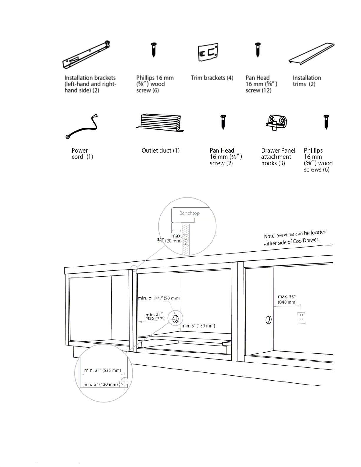
The switched power outlet must be outside the refrigerator drawer cavity so that it is accessible after
installation.
The switched power outlet must be located outside the cavity, within 1400mm (55") from the CoolDrawer
cavity if situated on the left-hand side of the cavity and within 840mm (33") if situated on the right-hand side of
the cavity.
The services hole in the refrigerator cavity needs to be large enough for the power supply plug to fit through.
840653
9
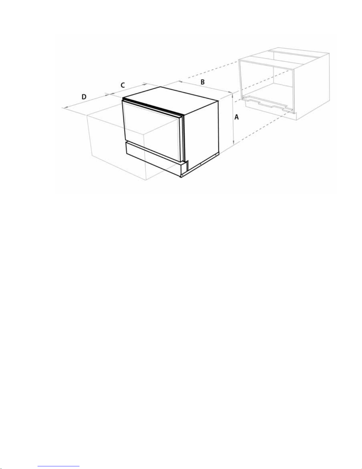
3.1 Product Dimensions
A Overall height of product (including installation brackets) 640mm / 25
3
/16”
B Overall width of product 855mm / 33
11
/16”
C Overall depth of product (excluding drawer panel, including power cord) 557mm / 21
15
/16”
D Depth of drawer (open) (excluding handle) 520mm / 20
1
/2”
840653
10
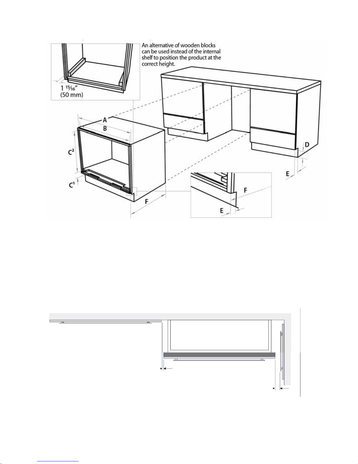
3.2 Cabinetry Dimensions
A Overall width of cabinetry frame 914mm (36”)
B Minimum inside width of cabinetry frame 864mm (34”)
C
1
Height below top of internal shelf* (to allow for outlet duct height) Max. 120mm (43/4”)
Min. 21mm (
7
/8”)
C
2
Height from frame inner face to top of internal shelf 644mm (253/8”)
D Minimum height of toe kick 75mm (3”)
E Minimum depth** of toe kick 40mm (1
5
/8”)
F Minimum distance from front of cabinetry to rear wall 560mm (22
1
/16”)
* Minimum internal height of cabinetry frame can be 644mm (25
3
/8”) if outlet duct is not used.
** All depth measurements are taken from the front face of the cabinetry frame (not drawer panel).
MINIMUM CLEARANCES
2mm (1/16”)
13mm (1/2”)
840653
11
3.3 Parts Supplied
CAVITY PREPARATION
# Recommended to allow the
vertical removal of the refrigerato
r
bins.
#
840653
12
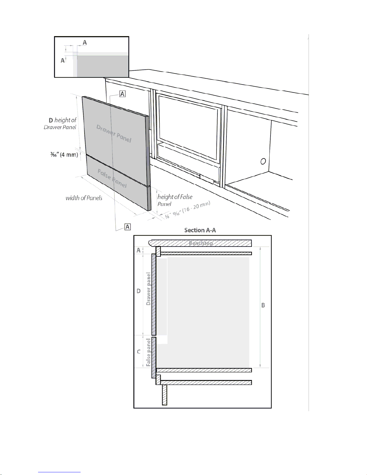
3.4 Integrated Panel Preparation

840653
13
3.4.1 Integrated Panel Material
• 16 – 20mm (
5
/8 – 13/16”) panel thickness (18mm (3/4”) recommended).
• Adequately sealed to withstand moisture (50
O
C/122OF @ 80% RH).
3.4.2 Height Of Drawer Panel
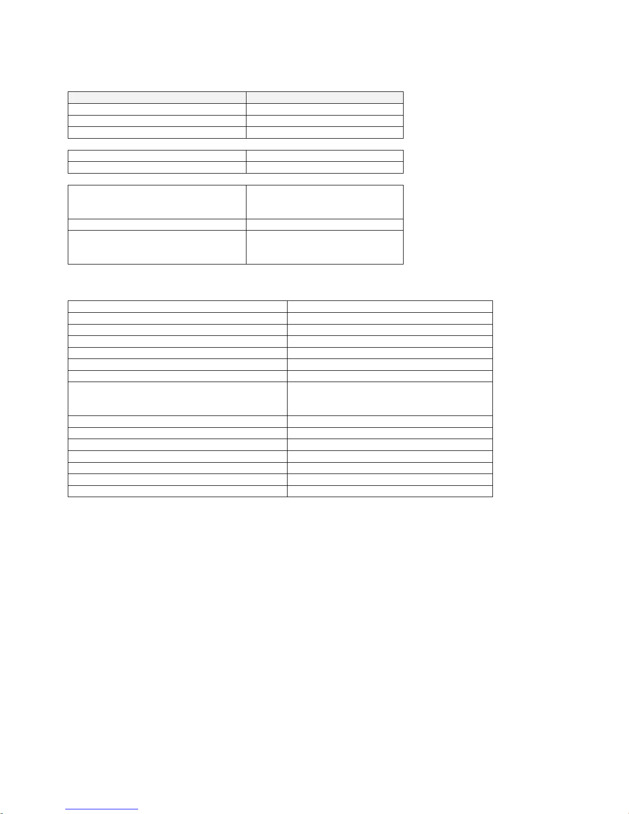
The following information is required to correctly define your Drawer panel height:
Dimension Data Source
A Reveal dimension Your kitchen designer
B Height between top of internal shelf and underside of benchtop Your kitchen designer
C Bottom face of Drawer panel to top of internal shelf Min. 152mm (6”)
Max. 184mm (7
1
/4”)
D Drawer panel height Calculated from A, B & C
To calculate D complete the following equation:
D = B - A - C
Example: B = 686mm (27”)
A = 20mm (
13
/16”)
C = 184mm (7
1
/4”)
Therefore D = 686mm – 20mm – 184mm = 482mm (27” -
13
/16” - 71/4” = 1815/16”)
3.4.3 Height Of False Panel
Determine the height of the false panel according to the individual kitchen cabinetry requirements,
maintaining a 4mm (
3
/16”) gap between panels.
The Fisher & Paykel prefinished panel width is 896mm (35”).
840653
14
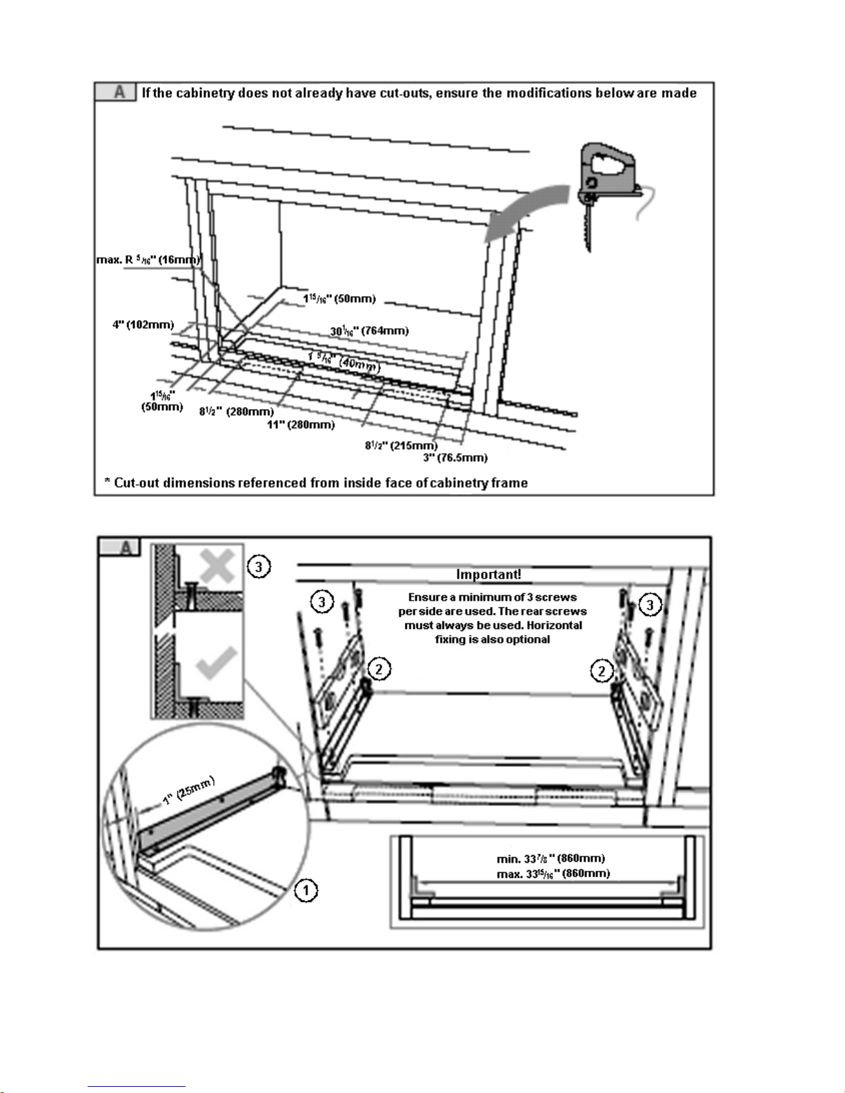
3.5 Create Cut-Outs In Frame
3.6 Locate And Secure Install Brackets
840653
15
3.7 Attach Inlet And Outlet Vent Ducts
3.8 Attach Power Cord And Trim Brackets

840653
16
3.9 Move Product Into Cavity
3.10 Fit Drawer Panel Attachment Hooks
840653
17
3.11 Attach Drawer Panel To Front Of Drawer
840653
18
3.12 Secure Trim Brackets To Cabinetry
3.13 Attach Trims To Sides Of Cabinetry
840653
19
3.14 Attach False Panel
3.15 Check Operation

840653
20
4 USING ALTERNATE ENERGY GENERATION
One of the big benefits of the Inverter drive motor technology found in CoolDrawer is that the motor is very
efficient in its energy usage. If running a CoolDrawer from alternate energy sources is being considered, the
following is a brief collection of facts and field observations to assist in making any decisions.
4.1 Product Facts
Average Power Usage.
When used in freezer mode 330kwh/year.
Peak Power Usage.
Peak power is controlled to less than 200W.
Motor Starting Surge.
The CoolDrawer brushless DC motor is electronically controlled. One of the big benefits of this type of
technology is that there is no power or current surge when the motor starts. Power is ramped up
progressively via the electronics.
Operating Voltage.
The CoolDrawer is guaranteed to operate on an AC sinusoidal voltage source of 230V rms +/- 15% at 50Hz
+/- 5%.
4.2 Using A Battery Driven Inverter Supply
There are many different brands and models of inverters available in the market today and often their output
voltage waveform is modified or non-sinusoidal. We sent an enquiry to an inverter manufacturer about
whether an inverter output had to comply with any regulatory standards or guidelines. The reply read:
”There are no guidelines that modified sine wave inverters are required to follow as pertains to the
amplitude, quality or shape of the output waveform. The only regulatory guidelines we choose to follow are
safety guidelines.”
As such we cannot guarantee the operation of a CoolDrawer running from an inverter supply if it does not
comply with our Operating Voltage requirements listed above.
Are there existing customers who are successfully running a CoolDrawer from an inverter supply? - Yes!
There are many installations where these types of refrigerators are successfully operating on an inverter
supply. In our experience, if an inverter meets the following technical criteria, then operation and reliability
should not be an issue:
• RMS Voltage: 230V +/- 15%
• Frequency: 50 Hz +/- 5%
• Peak Voltage: 400V peak
Some inverters have an rms voltage inside specification, but do so by having short duration high voltage
pulses. Some of these voltage pulses can be above 400V, which is higher than the rating of the controls. If
the controls are continuously exposed to these high voltages, it may lead to premature failure of the
electronics and/or the Inverter electronics.
Power Rating.
• 1kVA (1,000VA) minimum.
While the CoolDrawer only requires 200W peak power, the VA requirement is higher. Successful
installations have a rating of 1kVA min.
Some brands of inverters have an “Idle/Sleep” mode. (This puts the inverter in to idle/sleep mode when no
load is being applied). As the CoolDrawer uses less than 2 watts in the off cycle, these type of inverters
need to have the inverter “idle mode” turned off or disabled, as the electronics in the CoolDrawer will be
powered off in the off cycle.

840653
21
Do Fisher and Paykel recommend a brand and model of inverter to use? - No.
Due to the large number of brands and models, it is impractical, not to mention inappropriate, for us to
attempt to approve or disapprove the use of any particular inverter. We simply recommend that everything
possible is done to ensure any inverter used complies with the preceding technical recommendations.
Do Fisher and Paykel provide a guarantee for CoolDrawer electronic modules when run from an inverter
supply? - No.
Even though the design of inverters has improved immensely over the last few years, and the incidence of
reported problems is very low, we do not know the “quirks” of individual inverters. Should an inverter output
go outside our voltage recommendations then it may damage the CoolDrawer Electronics and this,
obviously, is beyond our control.
4.3 Using A Motor Driven Generator Supply
Motor driven generators typically generate a 230V rms. sinusoidal voltage output. Whilst the voltage shape
is better defined than an inverter, a generator can still develop high voltage pulses due to such things as:
• Noise of brushes.
• Surges due to other equipment coming on/off line.
• Surges due to start up - power down.
As such, the same technical recommendations as have been outlined in the preceding inverter supply
section are an excellent guideline if planning to use a generator supply. Please read these technical
recommendations thoroughly.
4.4 Summary
As has been already mentioned, there are many successful installations where customers are using
inverters or generators to power their refrigerators.
If our technical recommendations for inverters/generators are adhered to, we are not aware of any reasons
why operational or reliability problems should be experienced.
840653
22
5 USER OPTIONS
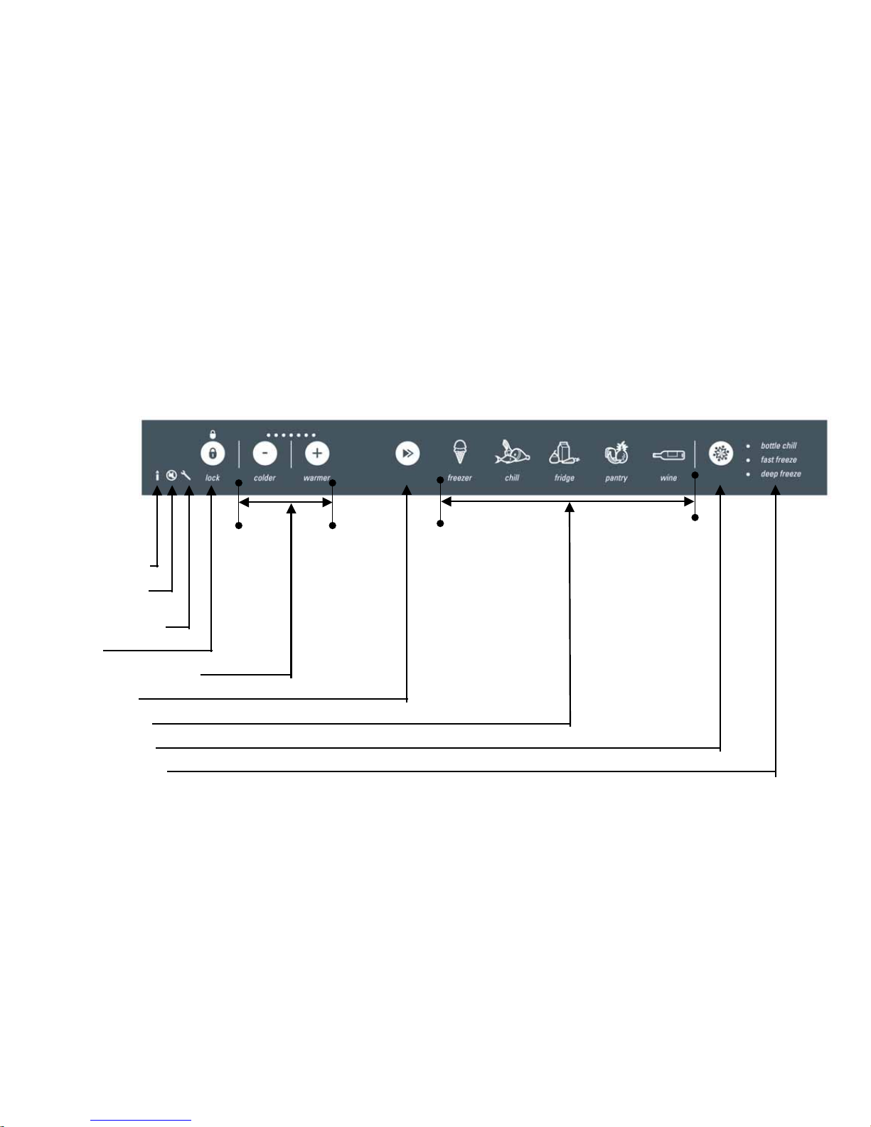
5.1 User Interface Display
Icons & Symbols
The following icons and symbols can be seen on the user display. Listed below is a short description of each and what they do.
Special
Options Mode
Control Beeps
Fault Alarm/
(Service required)
Lock
Temperature Adjustment
Mode Select
Storage modes
Function Select
Freezer Functions

840653
23
5.1.1 Lock
The Lock mode disables the control panel so that the storage environment cannot accidentally be changed.
The display will automatically lock after 15 seconds of the display not being used or whenever the drawer is
closed. The red lock icon will appear above the Lock button when the panel is locked.
To use the Lock mode:
• Press the LOCK button for 1 second to lock or 3 seconds to unlock the control panel.
5.1.2 Mode Select
The CoolDrawer has five operating modes: deep freeze, chiller, fridge, pantry and wine cooler. To change
the storage mode:
• Open the drawer.
• Press the LOCK button for 3 seconds to unlock the control panel.
• Within 15 seconds, press the MODE SELECT button to scroll to the required storage mode.
Note: The icon for the selected storage mode will flash until the compartment is at a suitable temperature for
food to be added into the compartment (this will take between 1 and 6 hours). All cabinets leave the factory
set to the Freezer mode by default.
5.1.3 Temperature Adjustment
Used to increase or decrease the temperature range within each mode selected.
5.1.4 Special Options Mode
To Enter Special Options Mode:
• Open the drawer.
• Press the LOCK button for 3 seconds to unlock the control panel.
• Within 15 seconds, press and hold the LOCK button, then within 1 second press the MODE SELECT
button and hold for 3 seconds until the Special Options mode icon is displayed.
When the appliance is in Special Options mode:
• The light will not operate when the drawer is opened.
• The door alarm will not operate.
• The display will not be illuminated except for the Special Options icon.
• Opening the drawer will not affect the compressor or fans.
• If the power to the appliance is turned off whilst in this mode, the appliance will continue in Special
Options mode when the power is restored.
Special Options mode will automatically de-activate 80 hours after activation.

840653
24
To de-activate earlier than 80 hours, press and hold the LOCK and MODE SELECT buttons for 3 seconds.
It is not necessary to unlock the display first.
5.1.5 Control Panel Beeps
The control panel beeps can easily be silenced if the customer prefers quiet operation.
To turn the control panel beeps off or on:
• Open the drawer.
• Press the LOCK button for 3 seconds to unlock the control panel.
• Within 15 seconds, press and hold the LOCK button, then within 1 second press the COLDER button
and hold for 3 seconds until the beep mode icon turns off or on.
Note: Silencing the control panel beeps will NOT prevent the drawer alarm from operating.
5.1.6 Fault Alarm
If the power/control module detects a fault that may affect operation, the fault icon on the display will flash
and an audible alarm will sound when the drawer is opened. The alarm will beep a number of times
representing the fault code number (refer to Section
10.1.2). The audible alarm will stop when any button is
pressed, but the fault icon will continue flashing.
When a fault occurs, a fault code will be displayed in the temperature display LEDs. (Refer to Section
10.1.)
5.1.7 User Modes
5.1.7.1 Freezer Mode (-18
O
C / 0OF)
For general frozen food storage.
To use Freezer mode:
• Open the drawer.
• Press and hold the LOCK button for 3 seconds to unlock the control panel.
• Press the MODE SELECT button within 15 seconds.
• Scroll to FREEZER mode.
• The Freezer mode icon will flash until the compartment is at a suitable temperature (this will take
between 1 and 6 hours).
5.1.7.2 Chill Mode (-0.5
O
C / 31OF)
Premium extra – cold storage for highly perishable fresh meat, fish and poultry.
Important:
This setting is not recommended for any other food or non-alcoholic drink items.
To use Chill mode:
• Open the drawer.
• Press and hold the LOCK button for 3 seconds to unlock the control panel.
• Press the MODE SELECT button within 15 seconds.
• Scroll to CHILL mode.
The Chill mode icon will flash until the compartment is at a suitable temperature (this will take between 1 and
6 hours).
 Loading...