

Fisher & Paykel 635 Active Smart, 680 Active Smart, 790 Active Smart, R600a, 900 Active Smart Service Manual
...Page 1
Service Manual
635 / 680 / 790 / 900 Active Smart®
Refrigerator/Freezer
R134a & R600a Systems
321144
Page 2

321144
2
Page 3

321144 - JULY 2012 REPRINT - AUGUST 2012
The specifications and servicing procedures outlined in this manual are subject to change without notice.
The latest version is indicated by the reprint date and replaces any earlier editions.
Fisher & Paykel Appliances Ltd
78 Springs Road,
East Tamaki
Auckland 2013
PO Box 58-732, Botany,
Auckland 2163,
New Zealand
Fisher & Paykel Australia Pty Ltd
A.C.N. 003 335 171
19 Enterprise Street
P O Box 798
Cleveland, Queensland 4163
Telephone: 07 3826 9100
Facsimile: 07 3826 9164
Telephone: 09 273 0600
Facsimile: 09 273 0656
Fisher & Paykel Appliances
5800 Skylab Road
Huntington Beach
CA 92647
Telephone: 888 936 7872
Fisher & Paykel Appliances Ltd U.K
Maidstone Road,
Kingston, Milton Keynes
Buckinghamshire, MK10 0BD
England
Telephone: 0845 066 2200
Facsimile: 0845 331 2360
COPYRIGHT © FISHER & PAYKEL LTD 2012 - ALL RIGHTS RESERVED
3
Fisher & Paykel Singapore Pte Ltd
150 Ubi Avenue 4
Sunlight Building #02-00
Singapore 408825
Telephone: 65 65470100
Facsimile: 65 65470123
Page 4

321144
CONTENTS
SPECIFICATIONS ...................................................................................................................................8
1
1.1 Cabinet Specifications – 230 - 240 Volt....................................................................................8
1.2 Cabinet Specifications – 110 - 115 Volt..................................................................................10
1.3 Compressor Specifications – R134a – 220 - 240 Volt............................................................11
1.4 Compressor Specifications – R600a – 220 - 240 Volt............................................................12
1.5 Compressor Specifications – R134a – 110 - 115 Volt............................................................13
1.6 Model Number Identification – 635 / 680 / 790 .......................................................................14
1.7 Model Number Identification – 900 .........................................................................................15
2 SERVICING REQUIREMENTS..............................................................................................................16
2.1 Specialised Service Tools.......................................................................................................16
2.1.1 Static Strap .........................................................................................................................16
2.1.2 Interface Light Pen Mk 2 ....................................................................................................16
2.2 Health & Safety .......................................................................................................................16
2.2.1 Good Work Practices.........................................................................................................16
2.2.2 Environmental Health And Safety ......................................................................................16
2.2.3 Good Practice And Safety..................................................................................................16
3 INSTALLATION INSTRUCTIONS .........................................................................................................17
3.1 Levelling ..................................................................................................................................17
3.2 Door Hinging (Tasman Models Only) .....................................................................................18
3.3 Air Space Requirements .........................................................................................................18
3.4 Temperature Adjustment ........................................................................................................18
4 THEORY OF OPERATION ....................................................................................................................19
4.1 Terms ......................................................................................................................................19
4.2 Internal Air Flow ......................................................................................................................20
4.2.1 Ice & Water Models............................................................................................................20
4.2.2 Non Ice & Water Models ....................................................................................................21
4.3 Defrost Cycle...........................................................................................................................22
4.3.1 R134a System....................................................................................................................22
4.3.2 R600a System....................................................................................................................23
4.4 The Refrigeration Circuit .........................................................................................................24
4.5 Evaporator...............................................................................................................................24
4.6 Condensate Disposal..............................................................................................................25
4.7 Filter Drier ...............................................................................................................................25
4.8 Internal Condenser .................................................................................................................26
4.8.1 Condenser Lay Out 635 / 680 / 790 "T" Models ................................................................27
4.8.2 Condenser Lay Out 635 / 680 / 790 / 900 "B" Models .......................................................28
4.9 Compressor Compartment Layout..........................................................................................29
4.10 Cross Rail................................................................................................................................29
4.11 Door and Door Hinge ..............................................................................................................29
4.12 Compressor.............................................................................................................................29
4.13 Thermal Fuse ..........................................................................................................................29
4.14 Drain Heater Wire ...................................................................................................................29
4.15 Divider Partition.......................................................................................................................30
4.16 LCD Display Panel ..................................................................................................................31
4.17 Door Switches .........................................................................................................................31
4.18 Defrost Heater.........................................................................................................................31
4.19 Low Ambient Heater................................................................................................................32
4.20 PC / FC Fans ..........................................................................................................................32
4.20.1 “B” Model Fan.....................................................................................................................32
4.20.2 “T” Model PC Fan...............................................................................................................33
4.21 Interior Light ............................................................................................................................34
4.22 Thermistor Temperature Sensors ...........................................................................................35
4.23 Basic Operation.......................................................................................................................36
4.23.1 Temperature Adjustment – Ice & Water Models ................................................................36
4.23.2 Temperature Adjustment – Non-Ice & Water Models ........................................................36
5 ELECTRONICS SECTION.....................................................................................................................37
5.1 Diagrammatic Overview Function Description........................................................................37
5.2 Control and Peripheral Functions ...........................................................................................38
5.3 Power/Control Module ............................................................................................................38
4
Page 5

321144
Display Module .......................................................................................................................39
5.4
6 VARIABLE CAPACITY COMPRESSOR ..............................................................................................40
6.1 Variable Capacity Compressor Control Overview .................................................................. 40
6.2 Built-in Electronic Protections (Within the Module/Inverter) ...................................................40
6.2.1 Compressor Start-up..........................................................................................................40
6.2.2 Overload Detection and Protection....................................................................................40
6.2.3 Power Limitation (Temperature Protection) ....................................................................... 41
6.2.4 Short Circuit Protection ......................................................................................................41
6.3 VCC Module/Inverter Identification.........................................................................................41
6.4 Fault Finding ...........................................................................................................................41
6.4.1 High Voltage Power Supply Circuit....................................................................................41
6.5 VCC-3 Inverter With Diagnostic Function...............................................................................42
6.5.1 Diagnostic Procedures.......................................................................................................42
6.5.2 Testing The VCC3 Inverter (With Diagnostic Function).....................................................44
7 DISPLAY INTERFACE – ICE & WATER MODELS .............................................................................48
7.1 Display Functional Schematic ................................................................................................48
7.2 Display Interface Features...................................................................................................... 49
7.3 Features..................................................................................................................................49
7.3.1 Icemaker On/Off.................................................................................................................49
7.3.2 Freezer Chill Mode.............................................................................................................49
7.3.3 Bottle Chill Mode ................................................................................................................49
7.3.4 Water Dispensing...............................................................................................................49
7.3.5 Sabbath Mode....................................................................................................................50
7.3.6 Key Silent Mode ................................................................................................................. 50
7.3.7 Dispenser Lock ..................................................................................................................50
7.3.8 Key Lock ............................................................................................................................50
7.3.9 Filter Replacement Alert ....................................................................................................50
7.4 Key Presses............................................................................................................................51
7.5 Temperature Settings .............................................................................................................51
8 ICEMAKER ............................................................................................................................................52
8.1 Ice Production.........................................................................................................................52
8.2 Information About The Icemaker ............................................................................................52
8.3 Ice Bin Full Sequence............................................................................................................. 52
8.4 Safety First..............................................................................................................................53
8.5 Icemaker Fill Tube Heater ......................................................................................................53
8.6 Pressure Limiting Valve ..........................................................................................................53
8.7 Water Inlet Valves...................................................................................................................53
8.8 Noises .....................................................................................................................................54
8.9 Ice & Water Common Complaints ..........................................................................................54
9 WATER DISPENSER ............................................................................................................................55
9.1 Installation Precautions / Warning ..........................................................................................55
9.2 Pressure Dispensing Pad .......................................................................................................55
9.3 Initial Use ................................................................................................................................55
9.4 Water Filter and Cartridge ......................................................................................................55
9.5 Changing The Water Filter......................................................................................................56
9.6 To Reset The Filter Icon .........................................................................................................56
9.7 To Disable The Filter Alarm ....................................................................................................56
10 DIAGNOSTICS ......................................................................................................................................57
10.1 Ice & Water Models................................................................................................................57
10.1.1 Fault Codes........................................................................................................................57
10.1.2 Testing Icemaker Sensor ...................................................................................................61
10.1.3 Testing Icemaker Motor .....................................................................................................61
10.1.4 Testing Water Valve...........................................................................................................62
10.1.5 Diagnostic Modes ..............................................................................................................63
10.1.6 Input / Output Status ..........................................................................................................65
10.1.7 Fault History ....................................................................................................................... 65
10.1.8 To Manually Force A Defrost .............................................................................................65
10.1.9 LCD Display .......................................................................................................................65
10.1.10 To Manually Force The Icemaker......................................................................................66
10.1.11 Data Download ..................................................................................................................66
10.2 Non-Ice & Water Models.........................................................................................................67
10.2.1 Fault Codes........................................................................................................................67
5
Page 6

321144
Diagnostic Mode For Service .............................................................................................70
10.2.2
10.2.3 Sensor Temperature Conversion .......................................................................................70
10.2.4 Input / Output Status ..........................................................................................................71
10.2.5 Data Download...................................................................................................................72
10.2.6 To Manually Force A Defrost .............................................................................................72
10.2.7 Show Room Mode..............................................................................................................72
10.2.8 Special Option Mode (Israel)..............................................................................................73
10.3 Problem Solving Checklist ......................................................................................................74
11 ICEMAKER & WATER DISPENSER SERVICE PROCEDURES .........................................................75
11.1 Component Replacement .......................................................................................................75
11.1.1 Icemaker PCB Replacement ..............................................................................................75
11.1.2 Icemaker Unit Removal ......................................................................................................75
11.1.3 Refitting Icemaker ..............................................................................................................75
11.1.4 Icemaker Temperature Sensor Replacement ....................................................................75
11.1.5 Water Valve Replacement .................................................................................................75
11.1.6 Display Module Replacement ............................................................................................76
11.1.7 Water Dispenser Pad Replacement...................................................................................77
11.1.8 Removing Water Tank........................................................................................................77
11.1.9 Refitting Water Tank...........................................................................................................78
11.1.10 Replacing Icemaker Fill Tube Heater ................................................................................78
11.1.11 Replacing PC Door On Ice & Water Models......................................................................81
11.1.11.1 Designer Doors.........................................................................................................81
11.1.11.2 Classic Doors............................................................................................................84
12 SERVICING PROCEDURES.................................................................................................................88
12.1 Safety Considerations .............................................................................................................88
12.2 Electrical Safety Test ..............................................................................................................88
12.3 Doors and Door Gaskets ........................................................................................................89
12.4 Removal Of Power/Control Module ........................................................................................89
12.4.1 Initialisation Of The Power/Control Module After Installation – Non-Ice & Water Models .90
12.5 Freezer Bin, Runner and Air Deflector Removal - E402B and E372B Models.......................90
12.6 FC Bin Removal - 900 Models ................................................................................................90
12.7 FC Drawer Removal - 900 Models .........................................................................................91
12.7.1 Refitting Of The FC Drawer................................................................................................91
12.8 PC Fan Motor - “T” Models .....................................................................................................92
12.9 PC Fan Motor - “B” Models .....................................................................................................92
12.10 Defrost Element Replacement ................................................................................................92
12.11 Thermal Fuse ..........................................................................................................................92
12.12 Cross / Base Rail Door Switches ............................................................................................93
12.13 Removal Of Display Module – Non-Ice & Water Models........................................................93
12.14 PC Sensor Replacement ........................................................................................................93
12.15 FC Sensor Replacement- “T” and “B” Models........................................................................93
12.16 FC Sensor Replacement - 900 Models...................................................................................93
12.17 Icemaker Temperature Sensor Replacement.........................................................................93
12.18 Replacement Of Low Ambient Heater - “T” Model..................................................................94
12.19 Replacement Of Low Ambient Heater - “B” Models ...............................................................94
12.20 Replacement Of Low Ambient Heater - “B” Model (In Return Grill) .......................................94
12.21 Interior LED Light Replacement..............................................................................................94
12.22 Flapper Element Replacement ...............................................................................................95
12.23 Block/Edge Connectors ..........................................................................................................97
12.24 Fan Cover Removal Tool (T Models Only) .............................................................................99
12.25 Active Smart® PC/FC Fan Motor Tester .................................................................................99
13 WORKING ON THE SEALED SYSTEM............................................................................................. 101
13.1 Safe Work Practices ............................................................................................................ 101
13.2 Leak Detection ..................................................................................................................... 101
13.3 R600a Operating Pressures ................................................................................................ 101
13.4 Reclaiming ........................................................................................................................... 101
13.5 Brazing Off The System....................................................................................................... 102
13.6 Pressure Testing Of The Refrigeration System ................................................................... 102
13.7 Transporting Of Refrigerators .............................................................................................. 104
13.8 Evaporator Replacement ..................................................................................................... 105
13.9 Refilling A Void In Foam Insulation After System Service Or Adjustment ........................... 105
13.9.1 Polyurethane Foam ......................................................................................................... 106
13.9.2 Safe Practices ................................................................................................................. 106
6
Page 7

321144
Removing Back Panel For Access To Water Lines And Joints............................................ 107
13.10
13.11 Embraco Compressor Fitted With External Overload ..........................................................108
13.12 Matsushita “D” Series Compressor Fitted With External Overload And Run Capacitor ......109
13.13 Compressor Replacement ....................................................................................................110
13.14 Compressor Fault Diagnosis ................................................................................................111
13.14.1 Compressor Won't Start - Dead (PTC Relay Fitted) ....................................................111
13.14.2 Compressor Won't Start - Hums......................................................................................112
13.14.3 Compressor Starts, Runs And Then Stops .....................................................................112
14 WIRING DIAGRAMS...........................................................................................................................113
14.1 Non Ice & Water Models Power Module Wiring Connections ..............................................113
14.2 Non-Ice & Water Models Wiring Diagram.............................................................................114
14.3 Ice & Water Models Power Module Wiring Connections...................................................... 115
14.4 Ice & Water Models Wiring Diagram ....................................................................................116
14.5 900 Models Power Module Wiring Connections - Reciprocating Compressor ....................117
14.6 900 Models Wiring Diagram - Reciprocating Compressor ...................................................118
14.7 900 Models Power Module Wiring Connections – VC Compressor..................................... 119
14.8 900 Models Wiring Diagram - VC Compressor....................................................................120
14.9 “B” Model Wiring Route ........................................................................................................121
14.10 “T” Model Wiring Route.........................................................................................................122
15 SERVICE REFERENCE ......................................................................................................................123
15.1 Service Reference ‘B’ Models ..............................................................................................123
15.2 Service Reference ‘T’ Models...............................................................................................127
16 FAULT FINDING FLOW CHART - SERVICING .................................................................................130
16.1 Refrigerator Not Operating ...................................................................................................131
16.2 No Power To Power/Control Module And/Or Display Module.............................................. 132
16.3 PC/FC Warm.........................................................................................................................133
16.4 FC Too Cold – PC Too Warm...............................................................................................134
16.5 PC Too Cold .........................................................................................................................135
16.6 Ice/Condensation Forming....................................................................................................136
16.7 No Light.................................................................................................................................137
16.8 Door Switch Not Operating ...................................................................................................138
16.9 Defrost Heater Faults............................................................................................................139
16.10 Compressor Faults ...............................................................................................................140
16.11 Compressor Runs Continuously...........................................................................................140
16.12 Compressor Will Not Run And Is Hot To Touch...................................................................141
16.13 Compressor Electrical Tests.................................................................................................141
16.14 Refrigeration System Faults .................................................................................................142
16.15 Not Dispensing Water...........................................................................................................143
16.16 Not Producing Ice .................................................................................................................144
7
Page 8

321144
1 SPECIFICATIONS
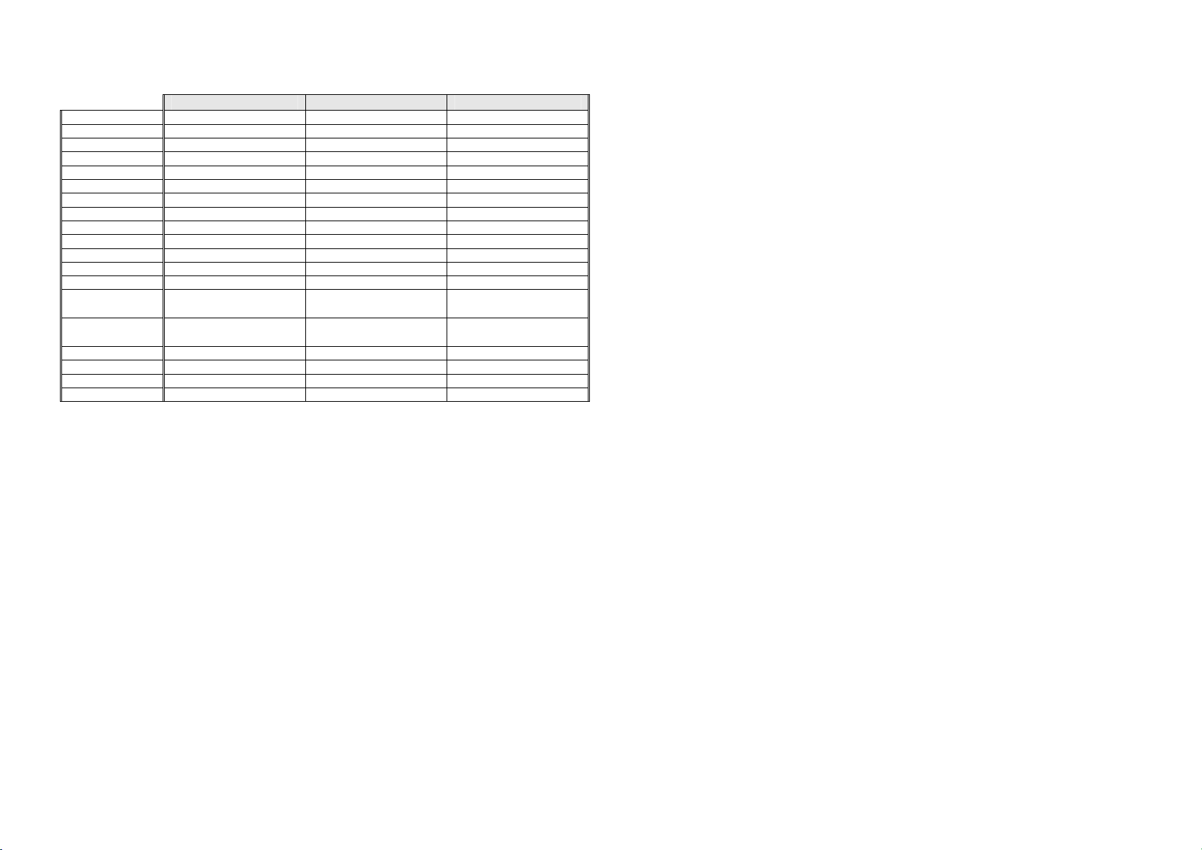
1.1 Cabinet Specifications – 230 - 240 Volt
DIMENSIONS
E331T E372B E381T E402B E406B E411T E413T E415H E440T
Height with
Standard Door
Height with
Designer Door
Depth 700 mm 700 mm 700 mm 700 mm 700 mm 700 mm 700 mm 700 mm 700 mm
Width 635 mm 635 mm 635 mm 635 mm 680 mm 635 mm 680 mm 635 mm 680 mm
CAPACITY GROSS VOLUME IN LITRES (AS 1430)
Refrigerator PC 232 litres 250 litres 283 litres 280 litres 271 litres 314 litres 314 litres 229 litres 342 litres
Freezer FC 97 litres 123 litres 97 litres 123 litres 133 litres 97 litres 97 litres 97 litres 99 litres
Humidity Dr N/A N/A N/A N/A N/A N/A N/A 85 litres N/A
TOTAL
ELECTRONICS – 230 – 240V (FOR SPARE PARTS)
Display Module P/No. 881218P P/No. 881218P P/No. 881218P P/No. 881218P P/No. 881218P P/No. 881218P P/No. 881218P P/No. 881218P P/No. 881218P
Display Module -
Ice & Water
Power/Control
Module - Non
RoHS
(AUS/NZ/ROW)
Power/Control
Module - RoHS
(UK/IRE/EU)
1425 mm 1595 mm 1595 mm 1700 mm 1700 mm 1700 mm 1595 mm 1700 mm 1700 mm
N/A N/A N/A 1710 mm N/A N/A N/A N/A N/A
329 litres 373 litres 380 litres 403 litres 404 litres 411 litres 411 litres 411 litres 441 litres
N/A N/A N/A P/No. 821074P N/A N/A N/A N/A N/A
P/No. 820817P P/No. 820817P P/No. 820817P P/No. 820817P P/No. 820817P P/No. 820817P P/No. 820817P P/No. 820817P P/No. 820817P
P/No. 820818P P/No. 820818P P/No. 820818P P/No. 820818P P/No. 820818P P/No. 820818P P/No. 820818P P/No. 820818P P/No. 820818P
SUCTION LINE ASSY (FOR SPARE PARTS)
R134a Models P/No. 813374 P/No. 817862 P/No. 813374 P/No. 817862 P/No. 817865 P/No. 817863 P/No. 817866 P/No. 817863 P/No. 817866
R600a Models N/A P/No. 821189 N/A P/No. 821149 P/No. 821149 N/A P/No. 821151 N/A P/No. 821150
DEFROST ELEMENT – 230 - 240V (FOR SPARE PARTS)
R134a Models
Wattage
R600a Models
Wattage
P/No. 820673
295W
N/A
P/No. 820673
295W
P/No. 821875
178W
P/No. 820673
295W
N/A
P/No. 820673
295W
P/No. 821875
178W
P/No. 820675
322W
P/No. 821876
196W
P/No. 820673
295W
N/A
P/No. 820675
322W
P/No. 821876
196W
P/No. 820673
295W
N/A
P/No. 820675
322W
P/No. 821876
196W
8
Page 9
DIMENSIONS
E442B E521T E522B RF540A/RF610A
Height with
Standard Door
Height with
Designer Door
Depth 700 mm 700 mm 700 mm (27.6”) 730 mm (28.7”)
Width 680 mm 790 mm 790 mm (31.1”) 900 mm (35.4”)
1700 mm 1700 mm 1700 mm (67”) 1780 mm (70.1”)
1710 mm N/A 1710 mm (67.3”) 1790 mm (70.5”)
CAPACITY GROSS VOLUME IN LITRES (AS 1430)
Refrigerator PC 307 litres 400 litres 360 litres (12.7 c/ft) 433 litres (15.3 c/ft)
Freezer FC 135 litres 117 litres 159 litres (5.6 c/ft) 181 litres (6.4 c/ft)
Humidity Dr N/A N/A N/A N/A
TOTAL
442 litres 517 litres 519 litres (18.3 c/ft) 614 litres (21.7 c/ft)
ELECTRONICS – 230 - 240V (FOR SPARE PARTS)
Display Module P/No. 814321P P/No. 814321P P/No. 814321P N/A
Display Module Ice & Water
Power/Control
Module - Non
RoHS
(AUS/NZ/ROW)
Power/Control
Module –RoHS
(UK/IRE/EU)
P/No. 821074P N/A P/No. 821074P P/No. 821074P
P/No. 820817P P/No. 820817P P/No. 820817P
P/No. 820818P P/No. 820818P P/No. 820818P
(RF610A)
P/No. 821024P
(RF540A)
P/No. 821025P
SUCTION LINE ASSY (FOR SPARE PARTS)
R134a Models P/No. 817865 P/No. 817866 P/No. 817864 P/No. 817864
R600a Models P/No. 821149 P/No. 821150 P/No. 821148 P/No. 821148
321144
DEFROST ELEMENT – 230 - 240V (FOR SPARE PARTS)
R134a Models
Wattage
R600a Models
Wattage
P/No. 820675
322W
P/No. 821876
196W
P/No. 860686
355W
P/No. 821877
240W
P/No. 860686
355W
P/No. 821877
240W
P/No. 860686
355W
P/No. 821877
240W
9
Page 10

321144
1.2 Cabinet Specifications – 110 - 115 Volt
DIMENSIONS
E402B E415H
Height with
Standard Door
Height with
Designer Door
Depth 694 mm 694 mm
Width 635 mm 635 mm
CAPACITY GROSS VOLUME IN LITRES (AS 1430)
Refrigerator PC 280 litres 226 litres
Freezer FC 123 litres 97 litres
Humidity Dr N/A 88 litres
TOTAL
ELECTRONICS – 100 - 110V (FOR SPARE PARTS)
Display Module P/No. 881218P P/No. 881218P
Display Module -
Ice & Water
Power/Control
Module
SUCTION LINE ASSY (FOR SPARE PARTS)
R134a Models P/No. 817862 P/No. 817863
DEFROST ELEMENT –100 - 110V 321W (FOR SPARE PARTS)
R134a Models
100V
110V
1700 mm 1700 mm
1710 mm N/A
403 litres 411 litres
P/No. 820174P N/A
P/No. 820819P P/No. 820819P
P/No. 820821P
P/No. 820699P
P/No. 820821P
P/No. 820699P
10
Page 11
1.3 Compressor Specifications – R134a – 220 - 240 Volt
E331T E372B E381T E402B E406B E411T E413T E415H
Make Matsushita Matsushita Matsushita Matsushita Embraco Matsushita Matsushita Matsushita Matsushita
Model DHS73C10RAW DHS73C10RAW DHS66C88RAW DHS73C10RAW EGZS90HLC DB77C14RAY DB77C14RAY DHS73C10RAW DHS66C88RAW
Part number 207216P 207216P 207215P 207216P 207188P 209492P 209492P 207216P 207215P
Volts 220 - 240 220 - 240 220 - 240 220 - 240 230 230 - 240 230 - 240 220 - 240 220 - 240
Hertz 50 50 50 50 50 - 60 50 50 50 50
Input Watts 123 123 113 123 129 / 153 147 147 123 113
Output Watts 210 210 190 210 226 / 278 213 213 210 190
Nominal BTU 717 717 649 717 770 / 950 742 742 717 649
Run current 0.57 amps 0.57 amps 0.53 amps 0.57 amps 0.71 amps 1.2 amps 1.2 amps 0.57 amps 0.53 amps
Refrigerant type R134a R134a R134a R134a R134a R134a R134a R134a R134a
Start Resistance 18.5 ohms 18.5 ohms 23.3 ohms 18.5 ohms 21.7 ohms 16.43 ohms 16.43 ohms 18.5 ohms 23.3 ohms
Run Resistance 18.4 ohms 18.4 ohms 19.7 ohms 18.4 ohms 10.4 ohms 11.62 ohms 11.62 ohms 18.4 ohms 19.7 ohms
Oil charge (cm3) 280 (Ester) 280 (Ester) 280 (Ester) 280 (Ester) 280 (Ester) 310 (Ester) 310 (Ester) 280 (Ester) 280 (Ester)
Relay PTC
Overload
Gas charge 120 Grams 130 Grams 120 Grams 140 Grams 150 Grams 150 Grams 130 Grams 140 Grams 130 Grams
Start Capacitor N/A N/A N/A N/A N/A N/A N/A N/A N/A
Run Capacitor
Inverter N/A N/A N/A N/A N/A N/A N/A N/A N/A
PTHTM330MD3
207276
5TM22NFBYY
207224
4µF
814809P
E440T E442B E521T E522B RF540A/RF610A RF540A/RF610A
Make Matsushita Matsushita Matsushita Matsushita Embraco Embraco
Model DB77C14RAY DB77C14RAY DHS77C13RAW DHS77C13RAW EGZS100HCL VEGY6H
Part number 209492P 209492P 207217P 207217P 207253P 819639P
Volts 230 - 240 230 - 240 220 - 240 220 - 240 220 - 240 220 - 240
Hertz 50 50 50 50 50 / 60 53 - 150
Input Watts 147 147 133 133 143 / 171 55.7 - 177
Output Watts 213 213 222 222 251 / 308 97 - 283
Nominal BTU 742 742 758 758 855 / 1050 330 - 965
Run current 1.2 amps 1.2 amps 0.64 amps 0.64 amps 0.8 amps 0.8 - 2.23 amps
Refrigerant type R134a R134a R134a R134a R134a R134a
Start Resistance 16.43 ohms 16.43 ohms 18.2 ohms 18.2 ohms 25.8 ohms 6.4 ohms
Run Resistance 11.62 ohms 11.62 ohms 15.2 ohms 15.2 ohms 9.84 ohms 6.4 ohms
Oil charge (cm3) 310 (Ester) 310 (Ester) 280 (Ester) 280 (Ester) 280 (Ester) 430 (Ester)
Relay PTC
Overload
Gas charge 140 Grams 150 Grams 155 Grams 150 Grams (5.3 oz) 180 Grams 180 Grams
Start Capacitor N/A N/A N/A N/A N/A N/A
Run Capacitor
Inverter N/A N/A N/A N/A N/A 207213
MM8-5DDT33M
209988
MM3-18GCF
209083
4µF
814809P
PTHTM330MD3
207276
5TM22NFBYY
207224
4µF
814809P
MM8-5DDT33M
209988
MM3-18GCF
209083
4µF
814809P
PTHTM330MD3
207276
5TM205NFBYY
207222
4µF
814809P
PTHTM330MP3
207276
5TM232NFBYY
207226
4µF
814809P
PTHTM330MD3
207276
5TM22NFBYY
207224
4µF
814809P
PTHTM330MP3
207276
5TM232NFBYY
207226
4µF
814809P
PTH7M220MD3
207080
4TM283NFBYY-53
207289
4µF
814809P
207080
7M220MD3
4TM302KFBYY
207259
4µF
814809P
MM8-5DDT33M
209988
MM3-18GCF
209083
4µF
814809P
N/A
N/A
N/A
MM8-5DDT33M
209988
MM3-18GCF
209083
4µF
814809P
PTHTM330MD3
207276
5TM22NFBYY
207224
4µF
814809P
PTHTM330MD3
207276
5TM205NFBYY
207222
4µF
814809P
321144
11
Page 12
321144
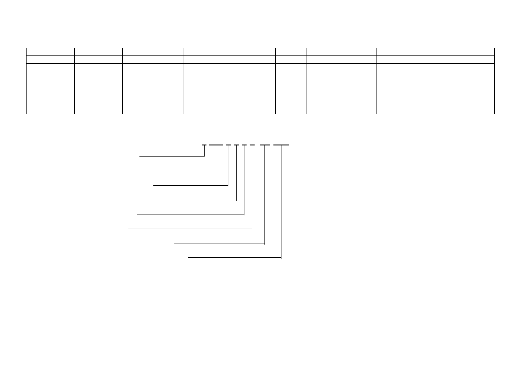
1.4 Compressor Specifications – R600a – 220 - 240 Volt
E372B E402B E406B E413T E440T
Make Embraco Embraco Embraco Embraco Embraco Embraco
Model EMB55CLC EMB66CLC VEMC9C EMB66CLC EMB66CLC EMB66CLC
Part number 207314P 207278P 207308P 207278P 207278P 207278P
Volts 220 - 240 220 - 240 220 - 240 220 - 240 220 - 240 220 - 240
Hertz 50 50 53 - 150 50 50 50
Input Watts 86 102 33 - 117 102 102 102
Output Watts 162 190 62 -210 190 190 190
Nominal BTU 553 648 213 - 715 648 648 648
Run current 0.4 amps 0.5 amps 0.28 - 0.86 amps 0.5 amps 0.5 amps 0.5 amps
Refrigerant type R600a R600a R600a R600a R600a R600a
Start Resistance 11.6 ohms 12.7 ohms 8.1 ohms 12.7 ohms 12.7 ohms 12.7 ohms
Run Resistance 21 ohms 15.9 ohms 8.1 ohms 15.9 ohms 15.9 ohms 15.9 ohms
Oil charge (cm3) 150 (Alquib/ISO5) 150 (Alquib/ISO5) 210 (Alquib/ISO5) 150 (Alquib/ISO5) 150 (Alquib/ISO5) 150 (Alquib/ISO5)
Relay PTC
Overload
Gas charge 50 Grams 50 Grams 50 Grams 55 Grams 52 Grams 52 Grams
Start Capacitor N/A N/A N/A N/A N/A N/A
Run Capacitor
Inverter N/A N/A 207309 N/A N/A N/A
EMB66QP2 20A
207292
4TM232KFBYY-53
207243
4µF
814809P
EMB66QP2 20A
207292
4TM232KFBYY-53
207243
4µF
814809P
E442B E521T E522B RF540A RF610A
Make Embraco Embraco Embraco Embraco Embraco Embraco Embraco
Model EGX80CLC VEMC9C EGX80CLC EGX90CLC VEMB11C VEMB11C EGX100CLC
Part number 207279P 207308P 207279P 207280P 207306P 207306P 207281P
Volts 220 - 240 220 - 240 220 - 240 220 - 240 220 - 240 220 - 240 220 - 240
Hertz 50 53 - 150 50 50 53.3 – 143.3 53.3 – 143.3 50
Input Watts 107 33 - 177 107 117 58 - 161 58 - 161 133
Output Watts 199 62 - 210 199 216 108 - 283 108 - 283 248
Nominal BTU 679 213 - 715 679 737 510 - 965 510 - 965 846
Run current 0.49 amps 0.28 - 0.86 amps 0.49 amps 0.85 amps 0.43 - 1.16 amps 0.43 - 1.16 amps 0.61 amps
Refrigerant type R600a R600a R600a R600a R600a R600a R600a
Start Resistance 22.45 ohms 8.1 ohms 22.45 ohms 22.45 ohms 8.1 ohms 8.1 ohms 17.6 ohms
Run Resistance 18.35 ohms 8.1 ohms 18.35 ohms 18.35 ohms 8.1 ohms 8.1 ohms 17.3 ohms
Oil charge (cm3) 280 (Alquib/ISO5) 210 (Alquib/ISO5) 280 (Alquib/ISO5) 280 (Alquib/ISO5) 210 (Alquib/ISO5) 210 (Alquib/ISO5) 280 (Alquib/ISO5)
Relay PTC
Overload
Gas charge 55 Grams 50 Grams 60 Grams 60 Grams 55 Grams 62 Grams 70 Grams
Start Capacitor N/A N/A N/A N/A N/A N/A N/A
Run Capacitor
Inverter N/A 207309 N/A N/A 207307 207307 N/A
PTH7M220MD3
207080
4TM189NFBYY-53
209890
4µF
814809P
N/A
N/A
N/A
N/A
N/A
N/A
PTH7M220MD3
207080
4TM189NFBYY-53
209890
4µF
814809P
EMB66QP2 20A
207292
4TM232KFBYY-53
207243
4µF
814809P
PTH7M220MD3
207080
4TM189NFBYY-53
209890
5µF
814812P
EMB66QP2 20A
207292
4TM232KFBYY-53
207243
4µF
814809P
N/A
N/A
N/A
N/A
N/A N/A
EMB66QP2 20A
207292
4TM232KFBYY-53
207243
4µF
814809P
PTH7M220MD3
207080
4TM283KFBYY-53
207154
5µF
814812P
12
Page 13
1.5 Compressor Specifications – R134a – 110 - 115 Volt
Make Embraco Embraco Embraco
Model EGZS70HLP EGZS70HLP VEGY6H
Part number 207206P 207206P 819652P
Volts 115 115 115
Hertz 60 60 53.3 - 150
Input Watts 116 116 55.7 - 177
Output Watts 204 204 97 - 283
Nominal BTU 695 695 330 - 965
Run current 1.04 amps 1.04 amps 0.8 - 2.23 amps
Refrigerant type R134a R134a R134a
Start Resistance 6.94 ohms 6.94 ohms 6.4 ohms
Run Resistance 4.88 ohms 4.88 ohms 6.4 ohms
Oil charge (cm3) 280 (Ester) 280 (Ester) 430 (14.54 oz) (Ester)
Relay PTC
Overload
Gas charge 140 Grams (4.9 oz) 120 Grams (4.2 oz) 180 Grams (6.3 oz)
Start Capacitor N/A N/A N/A
Run Capacitor N/A N/A N/A
Inverter N/A N/A 207214
E402B E415H RF540A/RF610A
7M4RMD3
207068
4TM319NFBYY
207205
7M4RMD3
207068
4TM319NFBYY
207205
N/A
N/A
321144
13
Page 14
321144
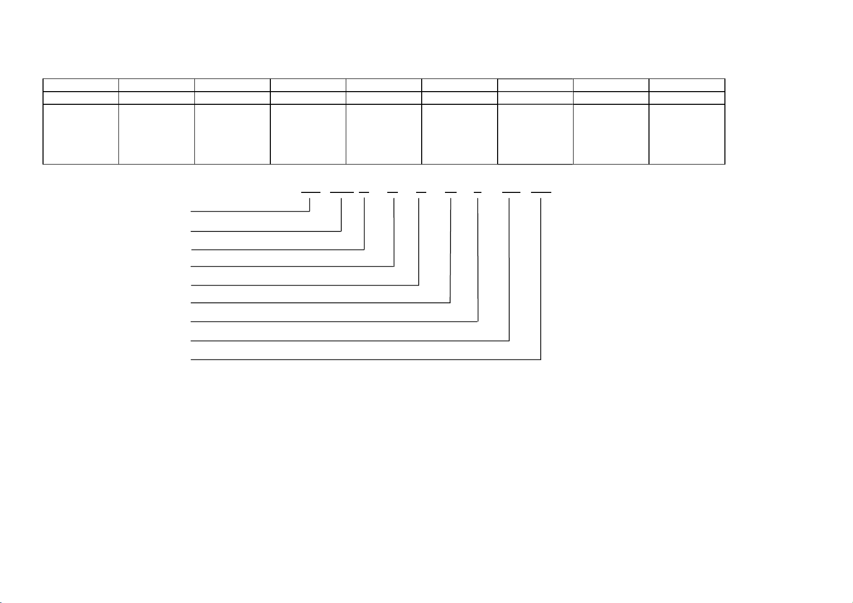
1.6 Model Number Identification – 635 / 680 / 790
1 2 3 4 5 6 7 8
E 402 B R E C FP WW
Type of
refrigeration
system
E = Electronic
Example:
E Electronic
402 Litres
B Bottom freezer
R Right hand hinged
E Elegance
C Series
FP Fisher & Paykel brand
WW White cabinet, white doors
Approximate
capacity of
cabinet in
litres
402 = 402 litres
Freezer location
T = Top freezer
B = Bottom freezer
H = Humidity drawer
Door hinging
R = Right hand
L = Left hand
Style
D = Designer
E = Elegance
I = Inox
M = Iridium
T = Tasman
E402BREC FP WW
Series Brand
FP = Fisher & Paykel
Colour of the cabinet and doors
WW = White cabinet / white doors
SA = Sandstone cabinet / sandstone
doors
SM = Silver cabinet / matt stainless doors
SX = Silver cabinet / brushed stainless
doors
14
Page 15
1.7 Model Number Identification – 900
1 2 3 4 5 6 7 8 9
RF 610 A D U M 2 FP SG
Product Type Capacity of
cabinet in
Litres
610 = 610
litres
RF Refrigerator
610 Litres/Cubic feet
A French Door
D Designer Handle
U Ice & Water
M Iridium
2 Iteration
FP Fisher & Paykel
SG Singapore
French
Doors
Designer
Ice & Water Colour
Handles
RF 610 A D U M 2 FP SG
321144
Iteration Brand Market
M = Iridium
X = S/S
Ezkleen
15
Page 16
321144
2 SERVICING REQUIREMENTS
2.1 Specialised Service Tools
For the servicing of this product, specialised tools are needed.
2.1.1 Static Strap
To be used as ESD protection when replacing any of the electronic boards.
2.1.2 Interface Light Pen Mk 2
Used in conjunction with a diagnostic programme on a laptop computer to retrieve and download data from
the electronic power/control module.
2.2 Health & Safety
2.2.1 Good Work Practices
1. Take care while removing all plastic components, especially when cold.
2. Leave the product clean and tidy when service work is completed.
3. Extreme heat in cabinets will cause plastic deterioration or distortion and thermal fuses in the
evaporator to go open circuit (be careful with heat guns).
2.2.2 Environmental Health And Safety
When servicing products, consider health and safety issues and requirements that must be adhered to at all
times. Specific safety issues are:
1. Electrical safety.
2. Electrostatic discharge.
3. Mixing of foam insulation.
4. Vapours while brazing.
5. Reclaiming of refrigerant.
2.2.3 Good Practice And Safety
1. Take care when removing or servicing all electrical components to avoid electrical shock or short
circuit conditions.
2. Take care when removing plastic components at low temperatures as breakages can occur with these
components.
3. Extreme heating of plastic components can cause distortion of those parts being heated.
4. Avoid overheating temperature sensitive devices such as the element thermal fuses and cabinet
sensors.
5. Avoid using solvents and citrus-based cleaners on all plastic parts. We advise only warm soapy water
be used.
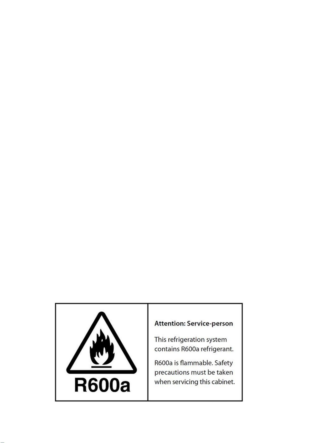
CAUTION – R600a REFRIGERANT (ISOBUTANE)
Some models of refrigerators contain R600a refrigerant within the sealed in system. This refrigerant is
flammable. All care must be taken when servicing these products. Vent well before brazing. Avoid any
open flames or ignition source.
16
Page 17
321144
3 INSTALLATION INSTRUCTIONS
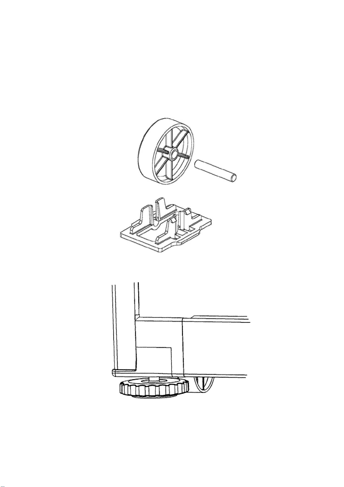
3.1 Levelling
The word 'level' is somewhat of a misnomer, as a 'spirit level' need not be used to set the appliance level. It
is preferable to have the appliance level in appearance where both doors will close with the aid of the door
closing cams. It is also important that the appliance sits solidly on the floor.
• Front and rear rollers are fitted ex factory. These are not adjustable.
• Cabinet levelling can be done by adjustment of the front levelling feet fitted ex factory. Refer to
Diagram
• Weight should be lifted off cabinet for ease of adjustment.
3.1B).
Diagram
Rear Roller
Diagram
Front Roller and Levelling Wheel
3.1A
3.1B
17
Page 18

321144
3.2 Door Hinging (Tasman Models Only)
The product leaves the factory hinged right hand or left hand. The door hinging can be changed by
obtaining a door hinge conversion kit appropriate for the cabinet being converted. There are a number of
kits changing the door hinging from RH to LH or from LH to RH. They also include two door B & T models,
single door models and “H” models in the 635, 680 and 790 cabinet widths, along with handle colours of
white and silver. Inox and Elegance models will require a complete door change.
3.3 Air Space Requirements
On all refrigerators and freezers it is important that an air gap is left around the product:
50mm (2 inches) clearance at the top.
20mm (¾ inch) clearance on each side.
3.4 Temperature Adjustment
Refer BASIC OPERATIONS in Section 4.23.
18
Page 19

321144
4 THEORY OF OPERATION
4.1 Terms
CABINET WRAPPER
Pre-painted steel.
LINER
A one-piece vacuum formed ABS liner with a plug-in divider
DIVIDER PARTITION
Injected moulding of HIPS, with two outer injected moulded housings, and an insulated ducted moulded
polystyrene inner core.
FAN MOTORS
DC 12 volt brushless variable speed fan motors for air circulation in both the FC and PC compartments.
EVAPORATOR
Aluminium fin on tube type mounted vertically on the back wall of the FC.
SUCTION and CAPILLARY LINE
Foamed into the back of the cabinet with all joints of the evaporator having been joined by induction brazing
in the FC.
POWER/CONTROL MODULE
Contains the microprocessor that controls all functions of the refrigerator and gathers data from the sensors.
This module also contains support circuitry to switch the various outputs.
DISPLAY MODULE
Using signals from the power/control module, this module generates the LCD or LED display.
REED SENSORS
A reed switch encapsulated within a plastic housing, mounted on the cross and base rails behind a plastic
cover. A magnet housed just under the lower end cap of each door activates this sensor when the door is
closed.
TERMS
Within this manual the following terms are used:
PC = Provision compartment
FC = Freezer compartment
LOW AMBIENT HEATER
Two types are used. A PCB type used in the air duct of “T” models. A blanket wire type used in the divider
of “B” models.
19
Page 20
321144
4.2 Internal Air Flow
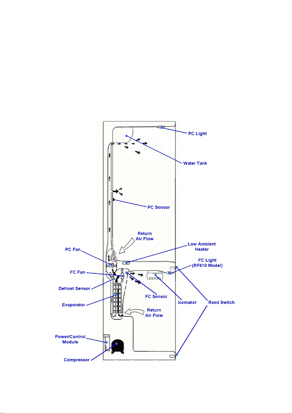
4.2.1 Ice & Water Models
The freezer fan draws air through the evaporator and into a duct in the rear wall of the freezer compartment.
This air exits through the fan grill at the top of the freezer compartment. The air behind the freezer coil cover
is also diverted through the divider partition to another fan, which supplies the cold air into the PC
compartment. The amount of air is controlled electronically by two sensors, which in turn regulate, through
the power/control module, the speed of both PC and FC fans to maintain selected temperatures in each
compartment.
Air from the PC returns to the FC evaporator by way of the return air duct, which is built into the divider
partition. This air is drawn across the evaporator by the FC fan motor to be recirculated again throughout
the PC/FC compartments.
Diagram
4.2
20
Page 21
321144
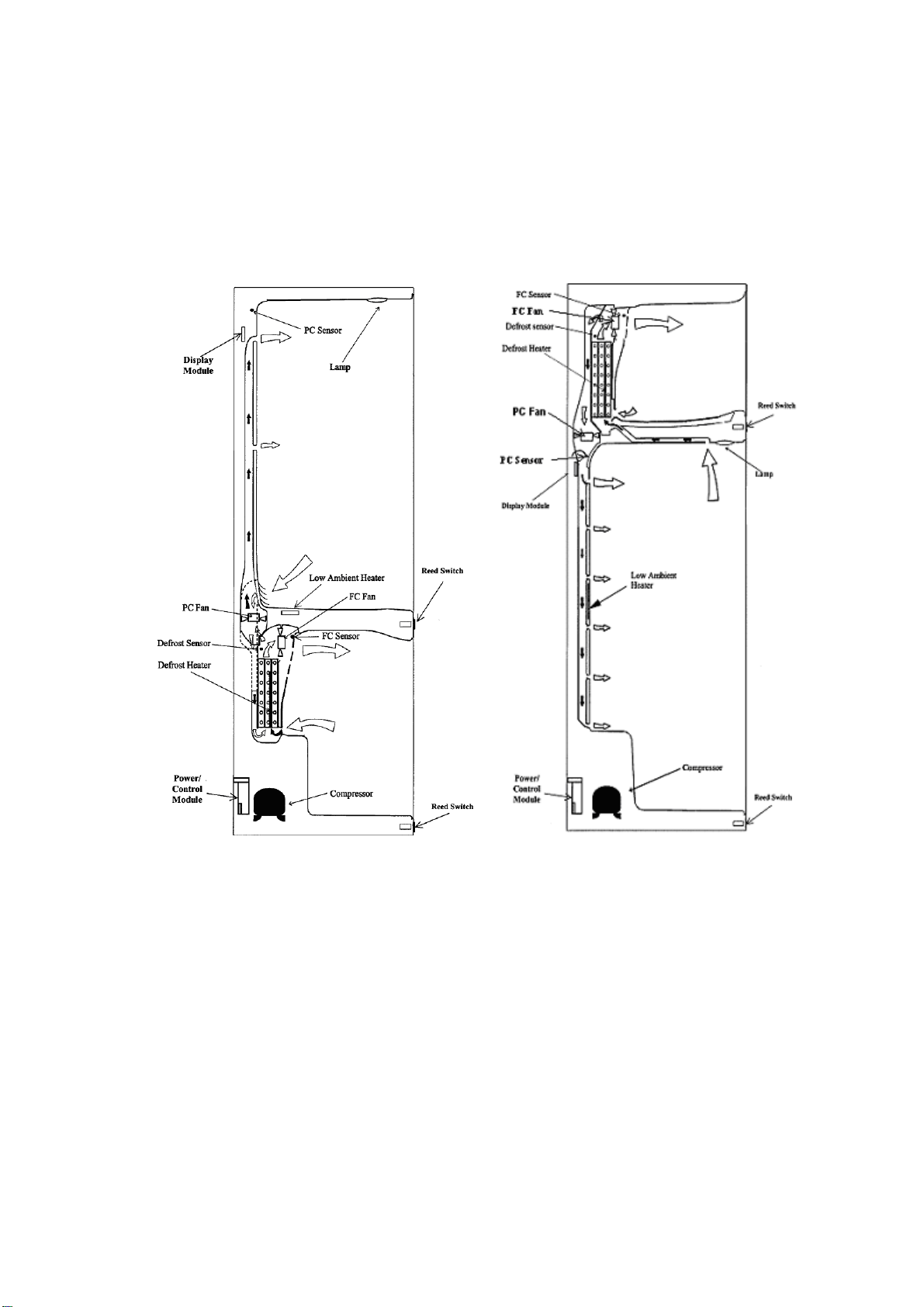
4.2.2 Non Ice & Water Models
The freezer fan draws air through the evaporator and into a duct in the rear wall of the freezer compartment.
This air exits through the fan grill at the top of the freezer compartment. The air behind the freezer coil cover
is also diverted through the divider partition to another fan, which supplies the cold air into the PC
compartment. The amount of air is controlled electronically by two sensors, which in turn regulate the speed
of both PC and FC fans to maintain selected temperatures in each compartment.
Air from the PC returns to the FC evaporator by way of the return air duct, which is built into the divider
partition. This air is drawn across the evaporator by the evaporator FC fan motor to be recirculated again
throughout the PC / FC compartments.
Diagram
“B” Model Active Smart
4.2.2A Diagram 4.2.2B
®
“T” Model Active Smart®
21
Page 22
321144
4.3 Defrost Cycle
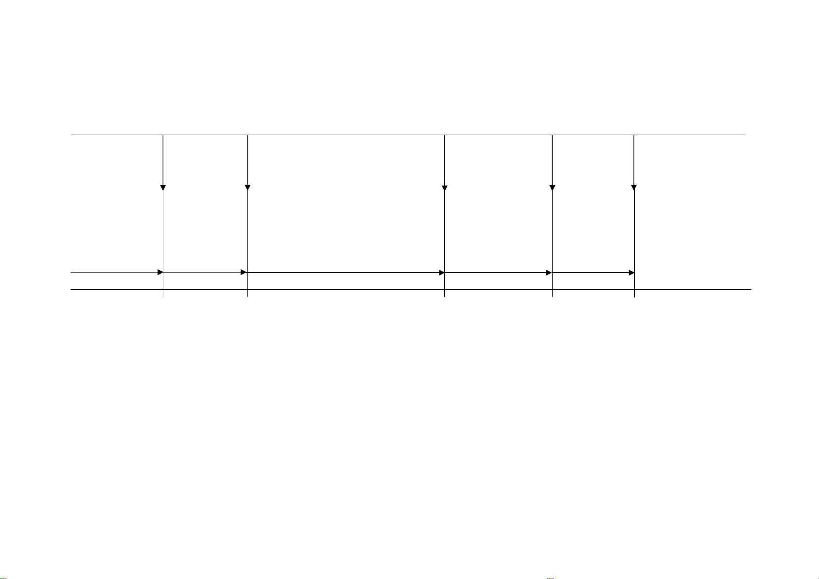
4.3.1 R134a System
The following table outlines the defrost cycle of an R134a refrigerant system Active Smart® refrigerator.
COMPRESSOR DEFROST ELEMENT DEFROST ELEMENT COMPRESSOR BOTH PC AND FC
TURNS OFF TURNS ON TURNS OFF TURNS ON FANS TURN ON
DEFROST TIME:
TARGET IS 18 MINUTES OR
SENSOR REACHES 8
2 MINUTES MAXIMUM IS 40 MINUTES 4 MINUTES 30 SECONDS
NORMAL RUN WARM UP DEFROST DRIP TIME DELAY BACK TO NORMAL RUN
If 40 minutes has elapsed, defrost
would be aborted if defrost sensor
has not reached 8
defrosts are aborted, Fault Code 2
is displayed.
O
C (46OF). If 2
O
C.
Diagram
4.3.1
22
Page 23
321144
play
4.3.2 R600a System
The following table outlines the defrost cycle of an R600a refrigerant system Active Smart refrigerator.
COMPRESSOR
TURNS OFF
DEFROST ELEMENT DEFROST ELEMENT COMPRESSOR
TURNS ON TURNS OFF TURNS ON
PC FAN PC FAN PC FAN FC FAN
TURNS ON TURNS OFF TURNS ON TURNS ON
DEFROST TIME:
TARGET IS 25 MINUTES OR
SENSOR REACHES 8
MAXIMUM IS 65 MINUTES 4 MINUTES 5 MINUTES 12.8 MINUTES
NORMAL RUN DEFROST DRIP TIME BACK TO NORMAL RUN
NOTE: The FC fan runs at a
If 65 minutes has elapsed,
defrost would be aborted if
defrost sensor has not
reached 8
are aborted, Fault Code 2 is
dis
O
C. If 2 defrosts
ed.
O
C.
lower speed than the
PC fan during these
12.8 minutes.
Diagram
4.3.2
23
Page 24
321144
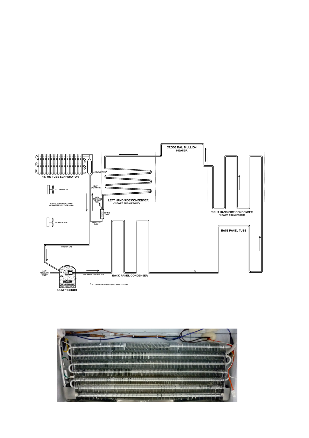
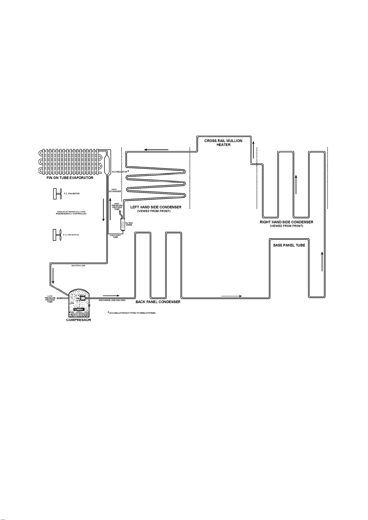
4.4 The Refrigeration Circuit
The compressor discharges high pressure, high temperature gas into the back panel condenser circuit first,
returning via the oil cooler in the compressor and entering the side condenser in the cabinet by way of the
base tube. This tube runs from the compressor compartment forward to the front bottom edge of the
cabinet, returning down the left hand side to be connected to the left hand side condenser coil.
A loop from this condenser coil forms the cross rail mullion on dual temperature cabinets. The condenser
then continues across the top front edge of the cabinet to form the right hand side condenser entering the
filter drier, which is mounted vertically in the unit compartment.
Now the high-pressure gas has been condensed, the liquid refrigerant flows through the capillary tube
entering the evaporator mounted in the freezer compartment. The liquid refrigerant then boils off due to the
low suction pressure applied to within the evaporator from the compressor. The heat-laden vapour is drawn
back to the compressor by way of the suction line to start the cycle all over again.
The above information relates to the cabinet, not the drawing below.
SINGLE EVAPORATOR TWIN FAN SYSTEM
Diagram
4.4
4.5 Evaporator
The evaporator on R134a models is of the Fin and Tube type with the expansion and suction inlet/outlet on
the left hand side. The defrost element is fitted to the left and right hand end plates of the evaporator and
clamped into position.
Diagram
24
4.5.1
Page 25
321144
The evaporator on R-600a models is of the Fin and Tube type with the expansion and suction inlet/outlet on
the left hand side. The defrost element is fitted to the right hand end plate of the evaporator and clamped
into position. The R-600a evaporator does not have an accumulator fitted. This is to reduce the risk of oil
slugging with the type of refrigerant used.
Diagram
4.5.2
4.6 Condensate Disposal
During the defrost cycle, which is electronically timed and controlled, live frost is melted off the evaporator by
means of heat from the defrost element. Condensate from the evaporator defrosting drops into a collection
trough, which has an outlet hole in the centre of the liner. A tube then allows the condensate to flow into a
water evaporation tray above the compressor.
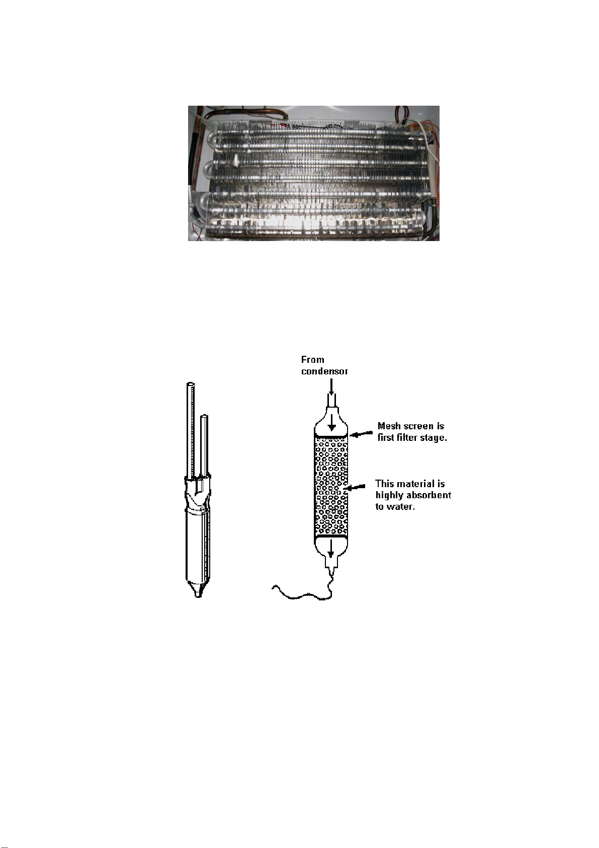
4.7 Filter Drier
Diagram 4.7
The filter drier or molecular sieve, as the name suggests, is both a filter and a drier. Whenever a system is
opened it is essential that the filter drier is replaced. ALWAYS ensure that replacement filter driers are kept
well sealed and airtight prior to being fitted to a system.
NOTE: When filter driers are replaced on systems being serviced, it is important that the filter drier is
either cut from the system or the desiccant is removed before heat is applied to the old filter drier.
Failure to do so will drive any moisture held in the desiccant back into the system.
ALWAYS mount vertically or as near to vertical as possible and use the correct desiccant to suit the
refrigerant being used.
XH7 or XH9 suits R-600a.
25
Page 26
321144
4.8 Internal Condenser
The internal condenser is made in three sections (refer circuit diagram below). One third of the condenser is
attached to the inside if the back panel, and the other parts are attached to the inside of the right and left
sides of the cabinet wrapper (as viewed from the back) all being foamed into place. It is very important, if
pressure testing the high side circuit, to split the condenser into its three sections to locate which section is
at fault. Always ease the back panel away from the cabinet slightly before pressure testing the internal pipe
work. This will prevent a pressure build-up within the cabinet should any leak be found internally in the foam
insulation. Such a leak could pressurise and damage the cabinet liner.
The back panel condenser comes as part of the back panel and should always be replaced as a complete
assembly if the back panel is ever removed. On fitting a new back panel assembly always replace the
mastic vapour-sealing compound before fitting the back panel into the triple fold of the cabinet.
Diagram 4.8
26
Page 27
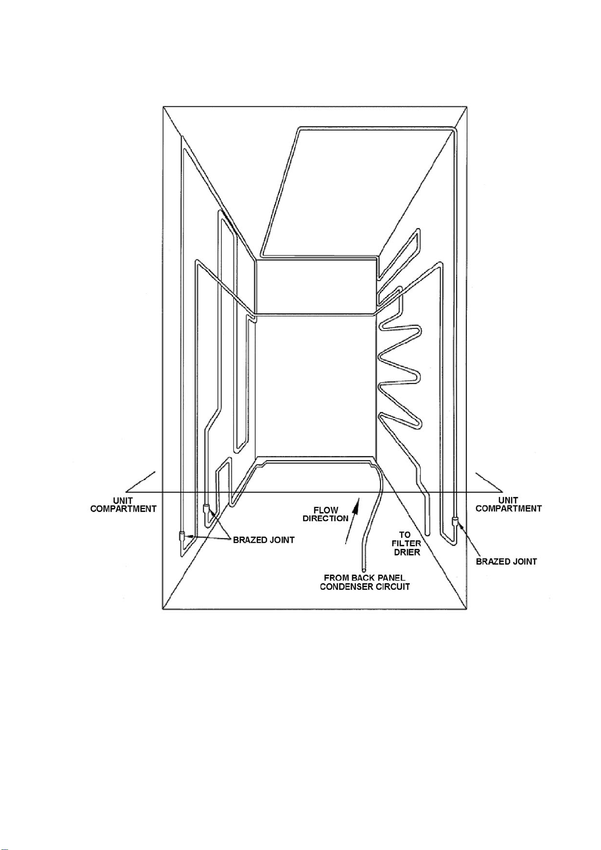
4.8.1 Condenser Lay Out 635 / 680 / 790 "T" Models
CONDENSER WITH TUBE CROSS RAIL
321144
BACK PANEL CIRCUIT REMOVED FOR CLARITY
ALL BRAZED CONDENSER JOINTS ARE EXTERNAL IN UNIT COMPARTMENT
Diagram
4.8.1
27
Page 28
321144
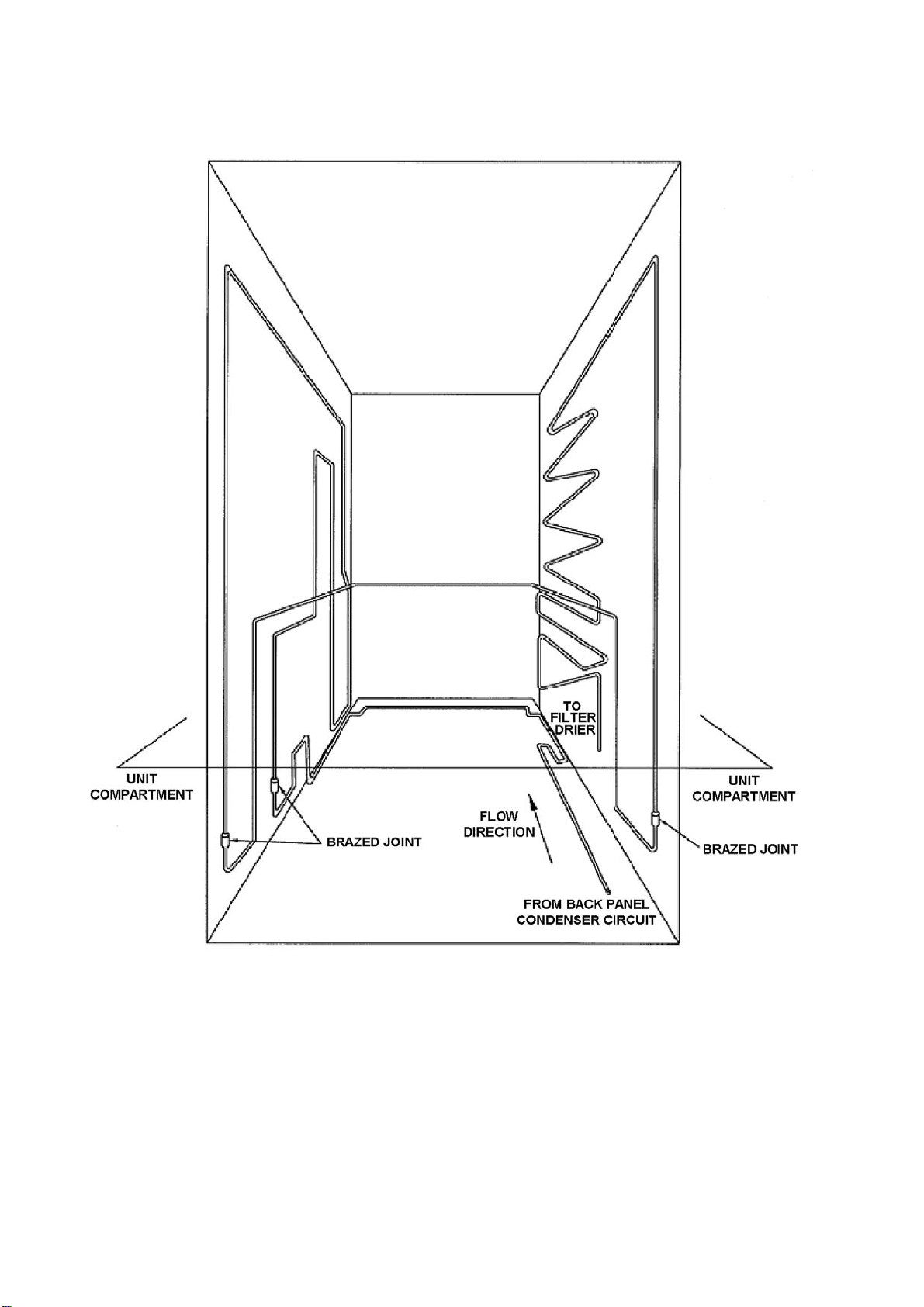
4.8.2 Condenser Lay Out 635 / 680 / 790 / 900 "B" Models
CONDENSER WITH TUBE CROSS RAIL
BACK PANEL CIRCUIT REMOVED FOR CLARITY
ALL BRAZED CONDENSER JOINTS ARE EXTERNAL IN UNIT COMPARTMENT
Diagram
4.8.2
28
Page 29
321144
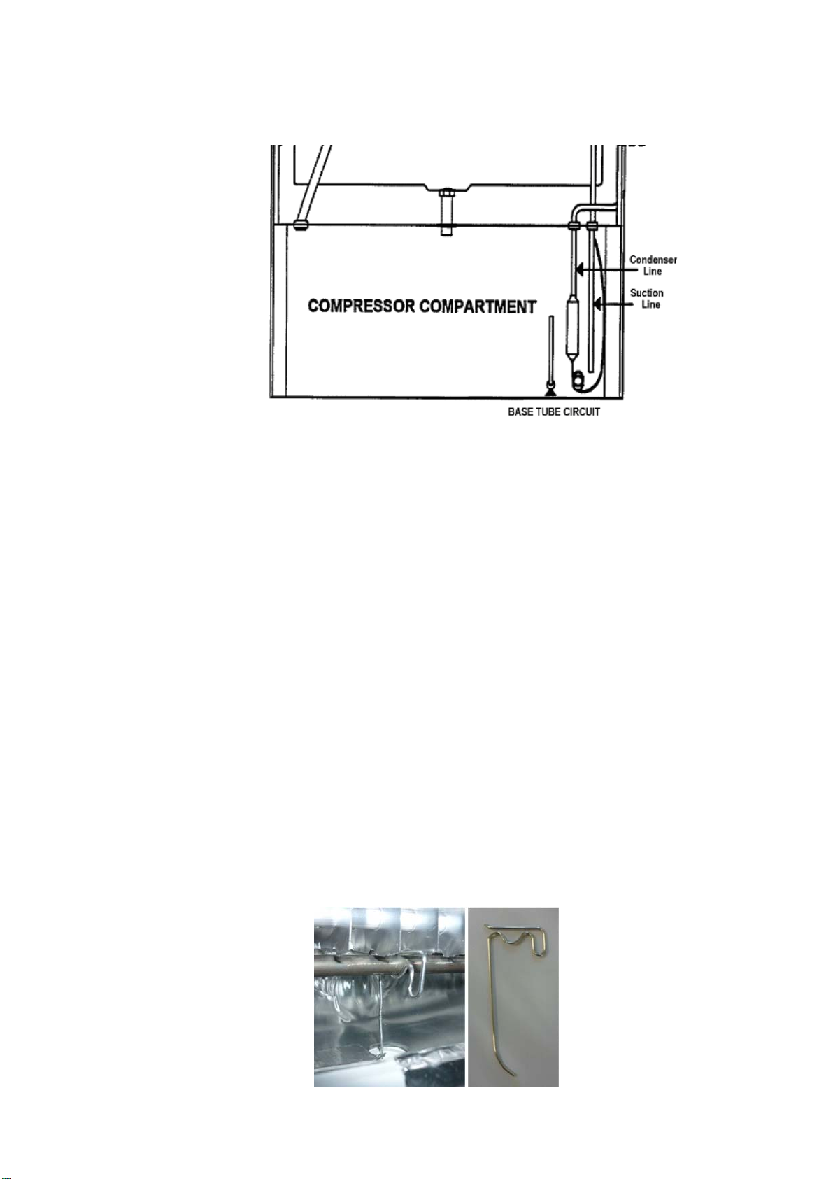
4.9 Compressor Compartment Layout
The diagrams below will assist in identifying the various pipes within the compressor compartment. They
should be read in conjunction with the full system diagram (refer to Diagram
4.4).
Diagram 4.9
4.10 Cross Rail
The cross rail contains part of the condenser copper tubing (mullion heater) providing heat to the gasket
area between the PC and FC compartments, preventing sweating of the gasket. Also mounted on the cross
rail is the Reed Sensor, under the plastic cover in the centre.
4.11 Door and Door Hinge
On the Designer models, the upper door hinge is concealed and cannot be seen with the door closed. The
upper door height is extended past the top of the cabinet to cover the hinge area.
4.12 Compressor
The compressor is turned on when cooling is required. It is switched by a Triac (solid state switching device)
on the power/control module.
4.13 Thermal Fuse
There are two thermal fuses mounted in the wiring harness of the defrost element, having a tripping
temperature of 72
assembly.
These fuses in both leads of the element protect the refrigerator from any over heating through failure of the
element itself or a triac failure in the power/control module. Both sides are protected in case phase and
neutral are reversed.
NOTE: Care should be taken if manually defrosting the evaporator if using heat guns, that the thermal fuses
are not over heated.
O
C. Once open circuit they cannot be reset. Replacement is part of the element heater
4.14 Drain Heater Wire
A drain heater wire is fitted to all cabinets except R134a B models. This drain heater helps to prevent the
drain tube from blocking with ice. The wire clips onto the double-pass defrost element, with the tail of the
heater wire in the drain tube, thus conducting heat from the defrost element into the drain tube area during
defrost.
Diagram
29
4.14
Page 30
321144
4.15 Divider Partition
This is moulded in two outer pieces and has an inner polystyrene moulded duct assembly that is wax coated.
This provides a barrier between the FC and PC compartments, also allowing return air from the PC to move
back to the FC evaporator in ‘T’ models. In both models it houses the PC fan motor. In ‘B’ models it houses
also the low ambient heater. The divider is fitted into the cabinet as an assembly and cannot be replaced.
“B” DIVIDER PARTITION
Diagram 4.15A
“T” DIVIDER PARTITION
Diagram 4.15B
30
Page 31

321144
4.16 LCD Display Panel
The ice & water models are fitted with an LCD display on the exterior of the PC door. This is the user
interface. Refer to Section
5 for further details of the display interface.
Diagram
4.16
4.17 Door Switches
“Reed” switches are used to detect the opening and closing of the doors. They are activated by two small
magnets that are built into the PC and FC doors. The reed switches are encapsulated within a plastic
housing, which is clipped under the plastic covers on the base and cross rails.
4.18 Defrost Heater
A heating element is used to defrost the ice accumulated on the evaporator. The defrost heating element
used on the evaporator is of an inconal folded type having both wiring terminations at one end. The defrosts
are adaptive to the usage and environment and are controlled by the power/control module and sensed by
the defrost sensor located on the evaporator chassis registering +8
element. Previous defrost history, the number of door openings, and the compressor run time are used to
determine the interval between defrosting. The typical time interval for defrosts is between 12 hours and 1
day. However it can be as short as 3 hours or as long as 70.8 hours depending on the usage and
environment.
O
C before terminating the defrost heater
R134a Evaporator Defrost Element
R600a Evaporator Defrost Element
Diagram
4.18
31
Page 32

321144
4.19 Low Ambient Heater
In low ambient temperatures, a 12 Volt, 7 Watt low power heater is used to keep the temperature in the
Provision compartment above freezing. The ambient heater is controlled by the power/control module,
which uses pulse width modulation (PWM) to run the heater at 58% to give 4.1 watts of heat. The ambient
heater is situated in the air duct of the “T” models and in the divider partition on “B” models. The element
has the purpose of warming the area if the ambient becomes too low, hence in the “B” models the element is
on when the compressor cycles off as the crispers could freeze. The low ambient heater in “T” models
operates when the percentage of compressor run time for the last four cycles drops below 30%. It switches
off when the percentage run time increases to above 35%. The heater will always be switched off during
defrosting. There may be less than 4 cycles in the calculation if a defrost has occurred or there were long
cycle times.
“T” MODEL
Diagram
4.19
4.20 PC / FC Fans
4.20.1 “B” Model Fan
There are two 12 Volt DC electrically commutated motors (ECMs). They provide the required cooling air
flow to both compartments. The motor speeds are controlled using a pulse width modulating (PWM)
technique. The power/control module controls the on/off of the compressor, and the fans. The speed of the
FC fan is set, and the speed of the PC fan is regulated using pulse width modulation.
The freezer compartment fan will always be set at the maximum FC fan speed, with the PC fan being
adjusted to meet the requirement of that compartment. We alter the speed of the FC fan under certain
loading conditions. Therefore the PC fan speed will be set at the average speed used from the previous
cycles under normal door openings and loading conditions.
When the compressor is turned on, provided the doors are closed both the fans will also be switched on
except immediately following a defrost cycle, where there is a delay of 5 minutes after the compressor has
started before the FC fan starts.
32
Page 33

321144
FC Fan (Viewed from front)
Diagram
“B” Model PC Fan (Viewed from PC side)
4.20.1
4.20.2 “T” Model PC Fan
The PC fan in the “T” model cabinets has an air shroud duct fitted to the base of the fan. This is to deflect
the airflow down the duct and prevent air leaks in the area of the top of the duct.
“T” Model PC Fan Fan in Position
NOTE: The same PC fan assembly is supplied as a spare part for both “B” and “T” models. This part
comes with the air shroud duct for use in “T” models. When the spare part is used in “B” models, the air
shroud duct should be discarded, as it is not used in “B” models.
Diagram
4.20.2
33
Page 34

321144
4.21 Interior Light
The interior light of this cabinet uses a LED mounted on a small PCB board located in the roof of the PC
(and FC in some models). The light fittings can be rectangle or oval.
On opening the door, the light has a soft start feature, increasing in brightness to a preset level. To prevent
overheating of the lens cover, the lamp is turned off after 5 minutes if the door is left open, and the module
will beep continuously indicating that the door has been left open.
“T” models have one LED on the PC board; “B” models have either two or three LEDs on the PC board.
The power/control module controls the light.
“T” Model PCB Board Board in Housing
“B” Model Board, Housing & Cover
Diagram
NOTE: It is important that the polarity to the LED lamp is correct, as it will not operate if transposed.
0
34
Page 35

321144
4.22 Thermistor Temperature Sensors
These sensors are used to monitor temperatures within the refrigerator. They are:
1. A defrost sensor mounted above the evaporator used to measure the temperature when in defrost.
2. An FC sensor mounted on the evaporator coil cover used to measure the temperature in FC.
3. A PC sensor mounted in the PC on the duct cover and used to sense the PC temperature.
4. On ice & water models, an ice tray sensor mounted on the bottom of the ice cube tray used to
measure the temperature of the ice tray.
5. On ice & water models, a water tank sensor mounted at the rear of the water tank used to measure
the temperature of the water tank.
Thermistor sensors are used for temperature measurement. Their electrical resistance changes as the
temperature changes. The table below lists some typical resistance values. The temperature can be read
using Diagnostic Mode as described in the Section
water models).
THERMISTOR SENSOR RESISTANCE TABLE
TEMPERATURE (°C)
-30.0 25.17
-25.0 19.43
-20.0 15.13
-15.0 11.88
-10.0 9.392
-5.0 7.481
0.0 6.000
5.0 4.844
10.0 3.935
15.0 3.217
20.0 2.644
25.0 2.186
30.0 1.817
35.0 1.518
40.0 1.274
45.0 1.075
50.0 0.9106
10.1.5 (ice & water models) or Section 10.2.3 (non-ice &
RESISTANCE
(K Ohms ±5%)
Diagram
4.22
35
Page 36

321144
4.23 Basic Operation
4.23.1 Temperature Adjustment – Ice & Water Models
To adjust Compartment Temperatures:
1. Use the MENU button to scroll to the TEMPERATURE screen on the LCD display.
2. Use the MENU button to select the compartment to change.
3. Use the UP or DOWN arrows to adjust the temperature. The temperature setting will be indicated on
the icon below.
Diagram
4.23.1
4.23.2 Temperature Adjustment – Non-Ice & Water Models
To adjust Compartment Temperatures:
1. Press the MODE button.
The provision compartment light on the refrigerator diagram will flash on and off. The temperature
indicator illustrated by a thermometer will show the temperature setting for this compartment.
2. The temperature can be altered by pressing the TEMPERATURE UP or TEMPERATURE DOWN
buttons. Fewer LED lights on the thermometer means a cooler temperature.
3. To adjust the freezer temperature press the MODE button again. The freezer temperature light will
flash on the refrigerator diagram.
4. The freezer temperature can be altered by pressing the appropriate TEMPERATURE UP or
TEMPERATURE DOWN buttons.
Successively pressing the MODE button will automatically select between the compartments. A return to the
provision compartment will be accompanied by a longer beep.
LEDs INDICATE APPROXIMATE TEMPERATURE
PC
FC
+10
+8
+6
+4
+2
0
Diagram
Temperatures shown are average temperatures. One degree C incremental temperature adjustment is
indicated by the “half” lights that illuminate as the temperature up / down button is pressed.
4.23.2
-12.5
-14.0
-15.5
-17.0
-18.5
-20.0
36
Page 37

321144
5 ELECTRONICS SECTION
5.1 Diagrammatic Overview Function Description
The electronic system consists of several parts:
Power/control module, display module, compressor, defrost heater, low ambient heater, door flapper heater,
produce compartment fan, freezer compartment fan, light, temperature sensors, icemaker sensors,
solenoids and door sensors.
The purpose of the power/control module is to turn on the compressor, which cools the evaporator, then to
use the fans to efficiently cool the compartments. Both fans turn on with the compressor. The freezer
compartment (FC) fan is kept at a constant speed while the produce compartment (PC) fan is regulated to
provide the balanced cooling for both compartments. The function of the microprocessor in the
power/control module is to provide independence of both compartments to their set temperatures, although
the environment of one compartment effects the other as they are linked by the ducts as can seen by the
internal air flow of the cabinet. (Refer to diagrams
ELECTRONIC FUNCTIONAL SCHEMATIC
4.2, 4.2.2A and 4.2.2B).
Diagram
5.1
37
Page 38

321144
5.2 Control and Peripheral Functions
The control system consists of the power/control module located in the unit compartment of the refrigerator,
the slave display module located either in the back of the produce compartment or, in the case of ice and
water models, on the outside of the door, and various sensors and actuators controlled by the power/control
module. The function and brief description of each of these units is defined below (refer to Electronic
Functional Schematic – Diagram
5.1).
5.3 Power/Control Module
There are two types of power/control modules used on these Active Smart® cabinets, one for the non-ice &
water cabinets and the other for those cabinets having the ice & water feature.
NOTE: While the two types of modules are not interchangeable, the ice & water module can be used on a
non-ice and water model.
This module is the electronic brain and control centre of the refrigerator. It contains a microprocessor,
support circuitry and switching devices. The power/control module controls the Provision Compartment (PC)
and Freezer Compartment (FC) temperatures by sensing the temperature and door state and operating the
compressor and fans accordingly. This module also houses the alarm beeper.
The speed of the fans is controlled by pulse width modulation (PWM). The power/control module controls
the motor speed by driving them with short pulses. These pulses vary in duration to change the speed of the
motor. The longer the pulses, the faster the motor turns, and vice versa.
The micro controller in the power/control module uses its internal memory for control; its ROM (Read Only
Memory), for program and fixed constant storage including tables, the RAM (Random Access Memory) for
variable storage and access. It uses an external Electrically Erasable Programmable Read Only Memory (E
2 PROM) for storage of variables and history data which is retained even when the power is turned off.
The power/control module contains a special type of memory device call an E 2 PROM. The information on
the fridge operation, faults and diagnostic information is stored in this memory. They include the
temperature setting, the history of FC, PC temperatures (approx 18 hours), defrost history (the last 12
defrosts) and fault history. This will help the service person find and remedy the cause of failure. All this
memory will be retained even when the fridge is disconnected from mains power supply.
Compressor Start Delay
All Active Smart
the compressor is off and compartments warm up above their respective switch (turn on) temperatures, and
the doors are open, the compressor will not switch on until one minute after the doors are closed. However,
the compressor will start after 90 seconds irrespective of whether the doors are open or not. (Primarily
introduced for Orthodox Jewish compliance to ensure there is no link between door opening and compressor
starting.)
The piezo beeper is used to signal prolonged door opening and other fault conditions:
1. The PC door alarm sounds if the door is left open for 90 seconds and the FC door alarm sounds if
door is left open after 60 seconds. Both PC and FC alarm will sound every 30 seconds until the door
is closed.
2. If the doors are left open longer than 5 minutes, the alarm will sound continuously and the PC light will
turn off. The alarm will stop with the closing of the door. The light is only reactivated by closing and
opening the door.
3. On non-ice & water models, all electronic faults, when detected, will sound the alarm and the LED’s on
the display module will flash indicating the fault code. The pressing of any button will cancel the alarm
but the fault code will remain until the cabinet has been serviced.
4. On ice & water models, a spanner symbol and LCD fault code will appear automatically if there is a
fault in the temperature measuring system, defrost system, icemaker, fans or low ambient heater.
When the PC door is opened, an alarm will sound. The number of beeps also indicates the fault code.
Pressing any of the control buttons can deactivate this alarm.
®
products will not start the compressor until one minute after both doors are closed, i.e. if
38
Page 39

®
There are two types of power/control modules used on these Active Smart
water cabinets and the other for those cabinets having the ice & water feature.
cabinets, one for non-ice &
321144
Non-Ice & Water Module Ice & Water Module
Diagram
5.3
5.4 Display Module
On the non-ice & water models, this module contains the user interface. It is controlled via a 5-wire
communications interface from the power/control module.
The user interface of push button switches and Light Emitting Diode (LED) display on the display module
printed circuit board is used to input and display the required set temperatures for the refrigerator
compartments.
The user interface is positioned at the right hand side of the fresh food compartment (PC). The interface
automatically displays the current temperature setting for the PC compartment. This is shown as a series of
LED lights on a thermometer symbol. To adjust the temperature of the PC, simply press the
TEMPERATURE UP or TEMPERATURE DOWN buttons to the appropriate setting (refer to Section
Press the MODE button on the left-hand side of the interface to select the FC compartment setting. The
indicator light will flash for 8 seconds to show a new compartment has been selected. Press the up or down
buttons to adjust the temperature as necessary.
Further presses of the MODE button will toggle between the PC and FC compartments.
Non-Ice & Water Display Module
4.23.2).
Diagram
39
5.4
Page 40

321144
6 VARIABLE CAPACITY COMPRESSOR
Some Active Smart® refrigerators are fitted with variable capacity compressors (VCC) depending on the
model and market. The compressor is turned on when cooling is required and is switched by the
power/control module sending a low voltage frequency signal to the inverter.
The VCC improves energy efficiency and maintains a more stable temperature in both the provision
compartment and the freezer compartment. The compressor windings are wired in a 3 phase star formation
with the resistance between any two pins being the same (6.4 ohms).
6.1 Variable Capacity Compressor Control Overview
The power/control module on VCC product is identical to that on non-VCC product. The power/control
module senses if it is connected to a VCC compressor and uses the appropriate algorithm.
The compressor can operate at speeds between 1590 and 4300 rpm inclusive. On the Fisher & Paykel
product we operate the compressor at a select number of different speeds between 1590 and 4300 rpm to
reduce the variation in sound produced by the compressor. An electronic module/inverter connected
between the power/control module and the compressor controls the speed. This it does by supplying a
modulated DC 3 phase supply to the compressor. Warning: Permanent damage will occur if the
compressor is directly connected to the AC supply line.
The power/control module monitors, amongst other things, the refrigerator compartment temperatures (via
thermistors) and the defrost cycle, and from this information sends signals to the electronic module/inverter
to determine compressor speeds.
Whenever the compressor starts, it is run at 2200 rpm for 2.5 seconds to establish lubrication, and is then
run at 1590 rpm for a further 27 seconds before changing to any other higher speed as requested by the
power/control module. This is to provide a softer start before the compressor potentially ramps up to some
higher speed.
Whenever the refrigerator is plugged in/turned on, and/or after a defrost, in the first cooling cycle the control
will run the compressor, after its initial start procedure, at its maximum speed, which is 4300 rpm. The
compressor will stay at its maximum speed until both compartments have reached their cut-out temperature,
at which point the compressor will switch off and the refrigerator goes into the warm-up cycle.
In the subsequent cooling cycles, the algorithm will vary the compressor speed according to the amount of
cooling required to achieve an average temperature in each compartment (as measured by the thermistors),
equal to the compartment set temperatures with a 1 hour run-time.
In low ambient, where the heat load and/or cabinet usage is low, the compressor will be likely to run at its
minimum speed (1590rpm), and switch off more frequently than once every hour, similar to most non-VCC
product.
When the compressor is running at slow speeds, the evaporator may not be fully flooded, but this is normal.
6.2 Built-in Electronic Protections (Within the Module/Inverter)
6.2.1 Compressor Start-up
In case any anomaly occurs during compressor starting, the control will wait 6 seconds before repeating the
start-up. If the compressor doesn’t start after 12 trials, the control will wait 8 minutes before repeating the
start-up procedure (this condition may be when pressures are not equalised between suction and discharge
sides in the refrigeration system, eg; after an interruption in the mains supply).
6.2.2 Overload Detection and Protection
The control can detect an overload condition by monitoring the current consumed by the compressor. If
overload is detected, the control reduces the current by reducing the speed of the compressor until the
overload disappears, when the speed will return to the required value.
If the overload increases, the control will continue to decrease the current until the minimum speed of 1590
rpm may be reached, at which point the compressor may “stall”, and the control will return to the start-up
procedure.
40
Page 41

321144
6.2.3 Power Limitation (Temperature Protection)
The control limits the power supplied to the compressor to 200 watts to keep all electrical components below
a safe operating limit. The power is limited in the same way as the current in the overload protection.
6.2.4 Short Circuit Protection
In a case where a short circuit occurs, (eg; motor winding damage, connection faults etc), the same current
limiting control is actuated to reduce further damage. In the case of a major failure, a fuse within the inverter
will break the current supplied to the control. This fuse cannot be replaced in servicing.
6.3 VCC Module/Inverter Identification
The module/inverter has an identification label giving the following information:
Inverter Version
Frequency:
50 – 60 Hz
Voltage:
11 = 115-127V
24 = 220-240V
VCC3
Electronic board version
11
A = Stand alone version box
F = Attached version box
56
XX
A
XX
Cable configuration
6.4 Fault Finding
6.4.1 High Voltage Power Supply Circuit
Whenever power is supplied to the refrigerator, there should always be mains voltage (230V or 110V as
supplied to the appliance by the household supply) in the high voltage harness between the power/control
module and the VCC module/inverter. Live testing of the inverter is NOT recommended. Check the
resistance of the compressor; check the continuity of the harness from the power/control module. If there is
continuity through the harness, replace the power/control module.
Ω Ω
VC COMPRESSOR FUSITE PINS
The later Active Smart
fault code to assist in the diagnostics of both the compressor and the inverter. It uses one single LED lamp
to convey, by means of flashes and the interval between flashes, the fact that the inverter is operating as it
should be or, if there is a fault, the current fault.
®
cabinets fitted with VCC use a new type of inverter (VCC-3 inverter) having a LED
Ω
41
Page 42

321144
6.5 VCC-3 Inverter With Diagnostic Function
This function has been added to the new generation of VCC inverter in order to help Service Technicians
diagnose faults.
6.5.1 Diagnostic Procedures
Diagnostic codes for VCC-3 inverter.
Through a translucent front cover, the VCC-3 inverter flashes a green LED to indicate a fault due to inverter failure,
compressor failure or lack of signal from the power/control module.
The LED flashes every 0.5 seconds inside a flash cycle, and each flash lasts 125 milliseconds.
Flashing Cycles:
Flash Code 1: 1 cycle every 15 seconds (1 flash every 15 seconds).
Flash Code 2: 2 cycles every 5 seconds (2 flashes every 5 seconds).
Flash Code 3: 3 cycles every 5 seconds (3 flashes every 5 seconds).
Flash Code 4: 4 cycles every 5 seconds (4 flashes every 5 seconds).
1 Flash - No failure detected.
2 Flashes - No signal from power/control module.
3 Flashes - Inverter failure.
4 Flashes - Compressor failure.
Figure 1 – Label on the VCC-3 inverter box Figure 2 – LED position on
the inverter box
Code Compressor
1 Flash
(every 15
seconds)
2 Flashes
(every 5
seconds)
3 Flashes
(every 5
seconds)
VCC-3 Diagnostic Codes
Probable Root Causes Service Action
Status
ON
OFF No signal from
OFF No signal from
OFF Compressor / inverter cable
No Fault Detected.
All OK with the inverter.
power/controller module.
- No power to power/control
module?
power/controller module.
interrupted (open circuit).
- Inverter damaged?
- Compressor winding open
circuit?
Check other refrigerator components in
case the system is not refrigerating.
Unplug VCC from the power supply and
wait 2 minutes.
Reconnect the VCC to the power supply
and wait for 12 minutes.
Check frequency cable connection.
Check the power to the power/control
module.
If the frequency cable connection and
power/control module are OK:
Replace the inverter.
Check inverter/compressor cable is
connected.
Check compressor winding resistance
across all three terminals of the
compressor fusite.
If the winding resistances are with in
specification and both inverter &
compressor cables are OK:
Replace the inverter.
42
Page 43

321144
Code Compressor
Probable Root Causes Service Action
Status
4 Flashes
(every 5
seconds)
OFF Compressor damaged /
system damaged.
Check compressor input power.
Check compressor winding resistance
across all three terminals of the
compressor fusite.
Check for earth leakage (current)
between the fusite pins and frame shell
of the compressor.
If these resistances or leakage are out
of specification:
Replace the compressor.
If the winding resistance is within
specification:
Check the inverter and compressor
cabling for open circuit.
Unplug the VCC from the power supply
and wait 2 minutes.
Reconnect the VCC to the power supply
and wait for 12 minutes.
If the inverter still shows 4 flashes code
and the compressor is OFF:
Replace the compressor.
LED OFF
(No LED
on)
OFF - No Input power signal.
- Inverter damaged.
Check the input power signal (230
volts).
If there is no signal:
Check the input power connection from
the power/control module.
If the voltage is within specification:
Unplug the VCC from the power supply
and wait 2 minutes.
Reconnect the VCC to the power supply
and wait for 12 minutes.
If the inverter has no LED showing and
the compressor is OFF:
Replace the inverter.
If the inverter has no LED showing and
the compressor is ON:
The diagnostic function of the inverter is
not working properly.
NOTE
• Before replacing the inverter or the compressor, check that there is no fault in the refrigeration system,
for example excessive head pressure on the high side, system over charged with refrigerant, blocked
capillary tube, etc.
• After each Service Action has been carried out, follow the next inverter LED fault indication.
43
Page 44

321144
6.5.2 Testing The VCC3 Inverter (With Diagnostic Function)
With the aid of a multi-meter, a number of points can be tested on the inverter while it is in a running state.
To carry out these tests the probes on the meter need to be sharp and have fine points. The inputs to the
inverter and the output can be checked.
44
Page 45

321144
Step 1 – Check the compressor windings resistance.
• With the refrigerator disconnected from the power supply, remove the compressor cover and unplug the fusite
terminal connection from the compressor.
• Select the Ohms range on the multi-meter and measure the resistance of all three windings. The
resistance should be the same across all three windings. Refer to winding resistances in compressor
specifications, Sections
• Check for leakage to ground from the windings within the compressor.
• Reconnect the fusite plug to the compressor and refit the compressor cover.
1.3, 1.4 and 1.5.
Ω
Ω Ω
Step 2 – Check the input voltage to the inverter.
• Remove the protective terminal cover from the inverter, reconnect the appliance to the power supply and
set the compressor running.
• Select the multi-meter to measure AC volts. With the probes measure the input voltage as shown at the
two terminals indicated or at the input harness edge connector.
A normal cabinet with no fault:
• Will measure mains voltage (110volts or 230volts) AC input into the inverter.
• The compressor will be running (this can be felt by placing a hand on the compressor shell).
• The LED on the inverter board will be flashing once every 15 seconds as all is normal.
AC input neutral/phase
OR
At the back of the edge
connector
45
Page 46

321144
Step 3 – Check the input frequency of the inverter.
• Switch the multi-meter to the frequency range (if it has one). The frequency input into the Inverter from
the power controller can be measured.
• There are two terminals alongside the edge connector that this measurement can be taken from in the
inverter. How fast the compressor is running will depend on how cold the PC & FC are. Depending on
the compressor and the speed it is running at at the time the reading is taken, the frequency will vary
between about 53Hz and 177 Hz.
• If unable to obtain a frequency reading from the power controller to the inverter, suspect the fault to be in
the power controller.
Meter switched to
Frequency Range (Hz)
Output Voltage
The measurement of an output voltage using a multimeter/voltmeter will not give a valid reading in a no load state,
because once the inverter is unable to "sense" the motor inductance on its output it will cease to operate.
The best method would be to use a current probe connected to an oscilloscope and measure one of the
output phases (blue, black or brown wires) from the inverter, while the inverter is still connected to the
compressor.
While it is appreciated that oscilloscopes and current probes are not commonly available to service
technicians, it is not a valid test to even try to measure the output voltage, and that is one of the reasons why
we have introduced this type of inverter with the built-in LED diagnostic feature.
46
Page 47

p
Compressor system fault suspected.
Disconnect power from the
appliance.
321144
Equipment Required
• Multimeter with
resistance () scale
and frequency (Hz)
scale.
Measure compressor winding
resistance between phases
Megger test between compressor
windings and compressor case.
Is insulation
between
windings and
case OK?
Yes
Measure VCC Signal and VCC
Mains harnesses for continuity and
inspect connectors for damage.
No
Are winding
resistances
OK?
(Refer Section 1
for compressor
specifications).
Yes
Compressor windings
damaged. Replace
compressor with new part.
• Insulation tester
(“megger”).
• Spare VCC Inverter.
No
Note: A damaged
compressor could cause
damage to the inverter
module. If the compressor
windings are damaged, the
inverter may need to be
replaced as well.
Are wires
continuous
and
connectors
undamaged?
Yes
With the refrigerator plugged in and
running, unplug the VCC Signal
harness and measure the frequency
of the signal.
Is signal
between
50Hz and
150Hz?
Yes
Suspect inverter module.
Replace inverter module
with new
art and test.
No
No
Harness damaged.
Replace harness with new
part.
Suspect power/control
module. Replace
power/control module with
new part and test.
Note: A damaged harness
could cause damage to the
inverter module. If the
harness wires have shorted
to each other or to the
refrigerator chassis, the
inverter may need to be
replaced as well.
Note: Damage to the
power/control module
which leaves all other
functions of the refrigerator
working correctly but the
compressor not running is
unlikely, but not impossible.
Please double-check that
there is no fault in the
inverter, compressor or
wiring before replacing the
power/control module.
47
Page 48

321144
7 DISPLAY INTERFACE – ICE & WATER
MODELS
MENU
DOWN
Menu
The MENU button allows the user to scroll through the main menu options (Chill, Temperature,
Ice and Settings)
Arrow Buttons
The ARROW buttons are used to scroll through the settings of each function.
Lock
The LOCK button enables and disables the water dispenser and all the buttons.
.
7.1 Display Functional Schematic
Inputs Outputs
Display Harness →
Tact Switches →
Display Module
UP
LOCK
→ Water Solenoid
→ Comms
→ LEDS
→ LCD DISPLAY
48
Page 49

7.2 Display Interface Features
• Icemaker on/off.
• Bottle chill mode – 10, 15, 20, 25, 30 minute timer with alarm.
• Freezer chill mode – nominated freeze time at lower temperature set point.
• Water dispensing.
• Sabbath mode enable/disable.
• Key silent mode enable/disable.
• Dispenser lock.
• Key lock.
• Filter replacement alert.
• Fault alert.
• Diagnostics.
• Temperature set points.
7.3 Features
7.3.1 Icemaker On/Off
This mode turns the icemaker on or off.
To access the ice mode, press the MENU button until ICE is highlighted.
Then use an ARROW button to scroll to the icemaker ON or OFF.
321144
7.3.2 Freezer Chill Mode
Freezer chill is a function that rapidly freezes food in the FC by
temporarily dropping the freezer to its coldest temperature set point for a
12-hour period.
To access, use the MENU button to scroll to FREEZER, then use the up
or down button to get fast freeze.
To deactivate manually, use the MENU button and scroll to FREEZER.
Press the DOWN button until the icon disappears.
7.3.3 Bottle Chill Mode
Bottle Chill allows the customer to put a bottle in the freezer for a
designated amount of time. When that amount of time has elapsed an
alarm will sound telling the customer to take the bottle out of the FC. The
freezer automatically changes to its lowest set point.
The times are 10, 15, 20, 25 and 30 minutes.
To activate this mode, use the MENU button to scroll to FREEZER, then
use the UP button until this icon appears. Use the UP button to select the
time in minutes. Once selected, the alarm countdown will commence.
7.3.4 Water Dispensing
This icon will animate when the water is being dispensed.
49
Page 50

321144
7.3.5 Sabbath Mode
7.3.6 Key Silent Mode
When in this mode, the alarms are deactivated and the interior light
and back light on the display will not come on. The interior fan will
not turn off when the door is opened.
When in this mode, the beeper does not operate when the buttons
on the keypad are pressed. NOTE: Faults, bottle chill, and the door
will still alarm when the refrigerator is set in Key Silent mode.
When this icon is displayed, it indicates the product is in Key Silent
mode.
To activate or deactivate, hold the MENU button for four (4)
seconds.
7.3.7 Dispenser Lock
This mode disables the water dispensing pad and prevents water
from being dispensed.
To activate this mode, press the LOCK button for 2 seconds.
7.3.8 Key Lock
This mode disables all the buttons.
To activate this mode, press the LOCK button for 4 seconds.
7.3.9 Filter Replacement Alert
This icon will appear when the water filter needs changing. The
filter needs replacing every 2800 Litres or 6 months. This will flash
when dispensing water.
To deactivate the warning, press the LOCK and UP buttons
simultaneously for 4 seconds.
50
Page 51

321144
7.4 Key Presses
To activate any mode, certain combinations of key presses are required.
The key-presses are as follows. Key presses used by the service technician are those shown shaded.
Version 2 LCD Display
Function Key Presses Action Press Time
Dispenser Lock
Lock
On/Off Hold down for 2 seconds
Key Lock
Diagnostic Mode Menu + Up
Manually Forced
Defrost
Sabbath Mode Lock + Menu + Down
Lock
+
Menu + Down
+
+ +
Disable Filter Alarm Menu + Up + Lock
+ +
Show Off Mode Menu + Down + Up
+ +
Filter Reset Lock + Up
+
Manually Force
Icemaker Harvest
Lock + Down + Up
+ +
On/Off Hold down for 4 seconds
On Hold down for 4 seconds
On Hold down for 4 seconds
On/Off Hold down for 4 seconds
On/Off Hold down for 4 seconds
On/Off Hold down for 4 seconds
Reset Hold down for 4 seconds
Activates
once
Hold down for 4 seconds
7.5 Temperature Settings
PC Setting
0.0OC 0.5OC 1.0OC 1.5OC 2.0OC 3.0OC 4.0OC 5.0OC 6.0OC 7.0OC 8.0OC
32OF 32.9OF 33.8OF 34.7OF 35.6OF 37.4OF 39.2OF 41OF 42.8OF 44.6OF 46.4OF
Colder Warmer
FC Setting
-21.0OC -20.0OC -19.5OC -18.5OC -18.0OC -17.5OC -17.0OC -16.5OC -15.5OC -15OC-14.0OC
-5.8OF -4.0OF -3.1OF -1.3OF -0.4OF 0.5OF 1.4OF 2.3OF 4.1OF 5OF 6.8OF
Colder Warmer
Default factory settings are +3
compartment.
NOTE: Crowbar setting for the PC is -4
are average temperatures.
O
C (37.4OF) for the provision compartment and -18OC (-0.4OF) for the freezer
O
C (24.8OF) and for the FC is -26OC (-14.8OF). Temperatures shown
51
Page 52

321144
8 ICEMAKER
8.1 Ice Production
The icemaker comes out of the factory defaulted to off. To turn the icemaker on, press the MENU button to
scroll until the ICE option has been scrolled to.
Press the UP or DOWN buttons to turn the icemaker on or off. When the cubes are frozen, the icemaker
motor will turn the ice cube tray and twist the tray causing the ice cubes to dislodge and fall out of the tray.
The tray will then return to its normal position and refill with water.
NOTE: If the FC is above -10
around, the icemaker will not operate.
8.2 Information About The Icemaker
• The icemaker moulds in these later cabinets
have 30% larger ice block moulds in the tray.
The tray can be identified by a number of
dimples in the middle of the side edge.
• The water fill time has been increased to 5.7 seconds to allow the tray to fill. This has been achieved by
the use of 16-watt inlet water valves, thus increasing the flow rate to both the water dispenser and the
icemaker unit.
• The solenoid valves are not interchangeable with those used on earlier model cabinets.
• The temperature of the FC needs to reach below -10
operate.
• When first switched on, the icemaker carries out a harvest with no water in the ice tray.
• Once the ice tray resumes its normal position, the water will fill the tray. At this stage it will calculate the
amount of time taken to do a cycle, and then flips. After this point it will run normally, calculating the
amount of time for each batch. The rate of production will depend on the temperature of the freezer.
NOTE: If the temperature is above -10
dispense.
• The cubes will be ejected from the mould into the ice bin. It is suggested that the ice cubes are levelled
with the ice scoop occasionally for maximum storage.
• The large and small freezer bins can be rotated if a large amount of ice is required.
To manually force a harvest.
Press the DOWN, UP and LOCK buttons together and hold for 4 seconds. The icemaker will rotate and
empty the contents of the ice tray, then return to its normal position. The ice tray will then fill with water.
NOTE:
• A forced harvest will operate without the product being down to temperature. If the harvest does not
work, the sensor may be not connected or may be open circuit. The icemaker sensor must be in circuit
for a forced harvest to work.
• When forcing a harvest of the icemaker, the bin must be in place for the harvest to occur.
O
C (14OF) or the ice bin is full, or has been removed, or fitted the wrong way
O
C (14OF) before the icemaker commences to
O
C (14OF), the ice/water tray will sit in this position and will not turn to
8.3 Ice Bin Full Sequence
When the ice bin is full, the icemaker starts a sequence of testing to ensure ice harvest can continue. If the
icemaker senses the bin is full, the motor resumes its normal position. Twenty minutes later, the testing
sequence commences until such time as the ice level is reduced by usage. The testing sequence happens
every 20 minutes.
Bin in position
Bin lever – senses if
there is a bin in position
or not.
If there is no bin, lever
will be in the down
position as shown.
52
Page 53

Bin full of Ice
321144
Lever sensing if ice bin is
full.
If bin is not full, icemaker
continues rotation to eject
ice.
8.4 Safety First
• When first placed into operation, discard the first bin of ice, as this will remove any impurities that may
have been in the water system.
• Do the same after vacations or extended periods when ice is not used.
• Ice cubes, when not used, will become cloudy, will shrink, and will taste stale. The ice bin will need to
be emptied and cleaned periodically.
• Avoid contact with moving parts of the ejector mechanism.
• Do not place fingers on the automatic ice making mechanism while the refrigerator is turned on.
8.5 Icemaker Fill Tube Heater
There is a heater located under the fill tube nozzle to prevent the fill tube from freezing. It is connected in
series with the low ambient heater.
8.6 Pressure Limiting Valve
The pressure limiting valve must be fitted between the water supply tap and the inlet hose to the refrigerator
to limit the pressure of the water supply. It must be fitted a minimum of 250mm (10 inches) from the tap to
prevent water hammer.
The valve has an outlet pressure of 600Kpa. The flow direction is marked by an arrow on the side of the
valve.
Diagram
8.6
8.7 Water Inlet Valves
The water inlet valves are rated at 16 watts and have a flow rate of 2 litres (0.5 gallon) per minute. Both
coils are coloured red. The earlier water inlet valves were coloured blue and rated at 10 watts. The16-watt
valve is not interchangeable with the older 10-watt valves.
Diagram
8.7
53
Page 54

321144
8.8 Noises
The introduction of ice & water into Active Smart® products introduced some unfamiliar noises, which are
normal. The noises are difficult to hear and may not be heard during the day, but during the night they may
sound louder.
Cracking Noise
The ice cracking is due to the ice tray being twisted to loosen the ice cubes in the ice tray.
Humming
There will be a low humming noise when the ice tray motor/gearbox rotates the tray to flip the ice cubes from
the tray.
Clunking Noise
Ice falling into the ice bin may initially make a noise that will lessen with subsequent harvests. The reason
for this is that initially there is no ice in the bin, but as the bin fills with ice the noise lessens.
Water Filling
After the ice tray empties and returns to its normal position, the water valve opens to fill the tray. The noise
will be a hissing or water running noise. How often this noise occurs will be dependent on the time the water
takes to freeze, form into ice blocks and then harvest into the ice bin.
8.9 Ice & Water Common Complaints
The following are common complaints/problems/concerns regarding ice and water, which may or may not
have occurred. Explanation for these faults is given for the serviceman to better deal with customers having
concerns.
Sublimation
When ice is not being used on a continual basis, cold dry air from the evaporator passes over the ice,
causing the ice to dehydrate (evaporate, moisture is removed) and the ice will slowly disappear.
Ice Sticking Together
If the FC door is left open for an extended period or the ice bin is removed and allowed to warm up, the
customer may find the ice cubes sticking together in the bin to form a large block.
Where a large block of ice is formed, the block will need to be removed to start the ice making process
again.
Another reason for large blocks of ice can be due to water leaking from the fill tube onto the ice tray and
overflowing the mould, check for leaking diaphragm in the water inlet valve.
Discolouration / Metallic Taste
Where the water or ice cubes are discoloured, they should not be used. If the water is a greenish-blue
colour the reason for this happening is copper oxide. This is not a common fault but may happen where the
water supply to the house is in a copper pipe but for whatever reason the pipe is not earthed. To overcome
this problem, the pipe work should be earth bonded to the earth of the house.
Bad Taste
Any fresh food, which is not sealed or wrapped when placed into the freezer, may contaminate the ice with
the taste of the unwrapped foodstuff. The ice will need to be thrown out and the ice-making process started
again. The customer must be advised to wrap all foodstuffs.
Ice Appears Cloudy
This problem occurs when air or air bubbles are in the water, which normally happens in the early stages
and will disappear with use.
Particles In Ice And / Or Water
This is normally due to a new filter where carbon dust in the new filter needs to be flushed out of the system.
The particles are harmless and safe for consumption; however, customers are advised to flush the system of
three (3) litres of water at every filter replacement (refer to Use and Care manual).
54
Page 55

321144
9 WATER DISPENSER
9.1 Installation Precautions / Warning
• DO NOT use with water that is microbiologically unsafe or of unknown quality without adequate
disinfection before or after the system. (WARNING – connect to potable water supply only.)
• DO NOT install on line pressures above 827 kPa (119 psi) or below 150kPa (22 psi).
• DO NOT use on hot water supply (38
• DO NOT cut any length of water tube shorter than 500mm (20 inches).
• DO NOT install near electrical wires or water pipes that will be in the path of drilling when selecting the
location of the filter system.
• DO NOT mount the filter in such a position that it will be struck by other items, such as wastebaskets, etc.
• DO NOT install the filter or any water tubing in direct sunlight, as prolonged exposure to light can weaken
plastic components.
• DO NOT install the filter in a location that is susceptible to freezing temperatures as damage to the filter
housing could occur.
• DO NOT screw the filter to the refrigerator.
• DO NOT install the filter or any water tubing in high temperature areas e.g. in a ceiling cavity.
• AVOID contamination of pipes during installation.
• DO NOT use copper tubing. The plastic tubing supplied should always be used.
• DO NOT continuously dispense water for longer than 2 minutes.
IMPORTANT
• All connections must be checked for leaks.
• If unsure of connection process and/or leaks, then contact your local plumber to install and check the
system for you.
• Ensure that the 6mm (¼”) tubing is routed away from sharp objects, sharp corners (beware of kinking
tube as this will stop water flow), clear of the refrigerator unit compartment and not in a location where it
can be squashed.
• Ensure that all push-fit connections are firmly pushed into place. The tube should push in 20mm (¾”)
before reaching the stop.
• If the tubing is removed at any point, re-cut the end and re-insert. The tubing must be fully inserted to
avoid leaks.
• To remove the tube from connection points, turn off the isolating tap, then push in the collet and gently
pull the tubing at the same time.
O
C [100OF] maximum).
9.2 Pressure Dispensing Pad
This pad is located at the rear of the dispensing area and is used to dispense water. Water can be
dispensed by pressing the dispenser pad. The display will light up and the water fill icon will appear when
the water is dispensed.
The dispenser will not operate while the PC door is open.
9.3 Initial Use
Press the glass or container into the pressure-dispensing pad.
Note: Pressing very hard against the water dispensing pad will NOT make the water dispenser operate any
faster or produce greater quantities of water.
Initially allow approximately a one-minute delay from when the pressure-dispensing pad is pushed until the
water is dispensed. While the tank is filling, no water sign will appear.
Dispense at least 8 to 10 litres (8 to 10 quarts) of water through the system, stopping intermittently to ensure
that air in the tank is flushed out. Failure to do so will result in excessive dripping from the dispenser.
9.4 Water Filter and Cartridge
The product is supplied with a water filter and cartridge. It is recommended that the filter be mounted in a
vertical position. Where the filter is positioned is up to the customer.
The replacement icon will appear and blink when the filter needs to be replaced. This is approximately every
6 months.
55
Page 56

321144
9.5 Changing The Water Filter
• Turn water off. It is also recommended that the pressure is released by dispensing water with the
tap off.
• Grasp and firmly twist the cartridge in an anticlockwise direction (to the left when installed in the
recommended orientation).
• Pull the cartridge away from the filter head (down when installed in the recommended orientation).
• Discard the old filter.
• Remove the protective cap on the spigot on the head of the new cartridge.
• Push the cartridge upwards towards the head while rotating it in a clockwise direction (to the right
when installed in the recommended orientation).
• Reset the filter icon on the display (this will be set to remind the customer the filter is due to be
replaced).
Diagram
9.5
9.6 To Reset The Filter Icon
• Press the UP and LOCK buttons for 4 seconds to reset the filter monitor.
Note: Do not reset the monitor before the filter is changed, or monitoring will be inaccurate.
9.7 To Disable The Filter Alarm
Disable the alarm if no filter is to be fitted.
• Press and hold the MENU, UP and LOCK buttons for 4 seconds to turn this feature on/off.
56
Page 57

321144
10 DIAGNOSTICS
10.1 Ice & Water Models
A spanner symbol and LCD fault code will appear automatically if there is a fault in the temperature
measuring system, defrost system, icemaker, fans or low ambient heater. (Refer to the diagram below.)
When the PC door is opened, an alarm will sound. The number of beeps also indicates the fault code.
Pressing any of the control buttons can deactivate these alarms.
Example: When a fault develops, the LCD fault code appears, together with the spanner (wrench) symbol.
After rectifying the problem, the fault code and spanner will disappear. Faults are only rectified when that
feature is used. So in the case of a defrost fault, the code will remain until a defrost is initiated and it is
successful.
10.1.1 Fault Codes
Fault Code 1
Reason: On the last power up, the power module failed self test.
Primary Action: Replace power module.
Fault Code 2
Reason: The previous 2 defrosts were aborted after 40 minutes.
Primary Action: Check defrost element assembly in the FC. If faulty, replace.
Fault Code 3
Reason: The resistance of all the temperature sensors are outside the normal range (> 45K
Ohms).
Primary Action: Check the 6-way RAST connector at the power module.
Secondary Action: Re-terminate the 6-way RAST connector.
Tertiary Action: Replace the power module.
Fault Code 4
Reason: The resistance of all the temperature sensors are outside the normal range (< 660
Ohms).
Primary Action: Check the 6-way RAST connector at the power module.
Secondary Action: Re-terminate the 6-way RAST connector.
Tertiary Action: Replace the power module.
Fault Code 5
Reason: The resistance of the FC sensor is outside the normal range
(> 45K Ohms).
Primary Action: Check the sensor connection at the power module.
Secondary Action: Replace the sensor.
Fault Code 6
Reason: The resistance of the FC sensor is outside the normal range
(<660 Ohms).
Primary Action: Check the sensor connection at the power module.
Secondary Action: Replace the sensor.
Fault Code 7
Reason: The resistance of the Evaporator sensor is outside the normal range
(> 45K Ohms).
Primary Action: Check the sensor connection at the power module.
Secondary Action: Replace the sensor.
57
Page 58

321144
Fault Code 8
Reason: The resistance of the Evaporator sensor is outside the normal range
(<660 Ohms).
Primary Action: Check the sensor connection at the power module.
Secondary Action: Replace the sensor.
Fault Code 9
Reason: The resistance of the PC sensor is outside the normal range
(> 45K Ohms).
Primary Action: Check the sensor connection at the power module.
Secondary Action: Replace the sensor.
Fault Code 10
Reason: The resistance of the PC sensor is outside the normal range
(< 660 Ohms).
Primary Action: Check the sensor connection at the power module.
Secondary Action: Replace the sensor.
Fault Code 11
Reason: The current measured for the ambient heater, PC fan and FC fan is lower than
expected.
Primary Action: Check the 6-way fan/LAH RAST connector at the power module.
Secondary Action: Re-terminate the 6-way fan/LAH RAST connector.
Tertiary Action: Replace power/control module.
Fault Code 12
Reason: The current measured for the ambient heater, PC fan and FC fan is higher than
expected.
Primary Action: Check the 6-way fan/LAH RAST connector at the power module.
Secondary Action: Re-terminate the 6-way fan/LAH RAST connector.
Tertiary Action: Replace the power/control module.
Fault Code 13
Reason: The low ambient heater is drawing less current than expected. Either the heater or
wiring is open circuit or the heater is faulty.
Primary Action: Check the wiring and connections at both the heater and the power module.
Secondary Action: Check the low ambient heater resistance. If not within limits, replace.
Fault Code 14
Reason: The low ambient heater is drawing more current than expected. Either there is a
short in the heater, or the heater is faulty.
Primary Action: Check the wiring and connections at both the heater and the power module.
Secondary Action: Check the low ambient heater resistance. If not within limits, replace.
Fault Code 15
Reason: The PC fan is drawing less current than is expected. Either the wiring is open
circuit or the fan is faulty.
Primary Action: Check the PC fan wiring and connections at both the fan and the power module.
Secondary Action: Check the fan. If faulty, replace.
Fault Code 16
Reason: The PC fan is drawing more current than is expected. Either the wiring is shorted
or the fan is faulty.
Primary Action: Check the PC fan wiring and connections at both the fan and the power module.
Secondary Action: Check the fan. If faulty, replace.
Fault Code 17
Reason: The FC fan is drawing less current than is expected. Either the wiring is open
circuit or the fan is faulty.
Primary Action: Check the FC fan wiring and connections at both the fan and the power module.
Secondary Action: Check the fan. If faulty, replace.
58
Page 59

321144
Fault Code 18
Reason: The FC fan is drawing more current than is expected. Either the wiring is shorted
or the fan is faulty.
Primary Action: Check the FC fan wiring and connections at both the fan and the power module.
Secondary Action: Check the fan. If faulty, replace.
Fault Code 19 Reserved.
Fault Code 20
Reason: The flapper heater current is low.
Primary Action: Check the Molex connections for the flapper heater.
Secondary Action: Check the resistance of the heater. If open circuit, replace the heater.
Fault Code 21
Reason: The flapper heater current is high.
Primary action: Check for short circuit of the heater. If faulty, replace the heater.
Fault Code 22
Reason: The resistance of the PC sensor 2 is outside the normal range (> 45K Ohms). PC2
sensor cold.
Primary Action: Check the connection at the module. Check the resistance of the sensor.
Secondary Action: Replace the sensor.
Fault Code 23
Reason: The resistance of the PC sensor 2 is outside the normal range (< 660 Ohms).
PC 2 sensor hot.
Primary Action: Check the connection of the sensor at the module. Check the resistance of the
sensor.
Secondary Action: Replace the sensor.
Fault Code 24
Reason: The resistance of the ice tray sensor is outside the normal range (> 45K Ohms).
Sensor cold.
Primary Action: Check the connections of the sensor at the module. Check the resistance of the
sensor.
Secondary Action: Replace the sensor.
Fault Code 25
Reason: The resistance of the ice tray sensor is outside normal range (< 660 Ohms).
Sensor hot.
Primary Action: Check the connections of the sensor at the module. Check the resistance of the
sensor.
Secondary Action: Replace the sensor.
Fault Code 26
Reason: The icemaker motor timed out.
Primary Action: The icemaker gearbox is not returning to the start position and ends signal to
controller.
Secondary Action: Check the gearbox, and if faulty, replace.
Fault Code 27
Reason: The icemaker motor current is high.
Primary Action: Check the motor for an obstruction. Check the wiring at both the icemaker
gearbox and the power module.
Secondary Action: Clear for an obstruction. Test the motor operations. Check the gearbox motor
resistance. If not within limits, replace motor.
Fault Code 28
Reason: The icemaker solenoid current is high.
Primary Action: Check the connections to the solenoid. Check the resistance of the solenoid.
Secondary Action: Correct loose connections. Replace the solenoid if faulty.
59
Page 60

321144
Fault Code 29
Reason: the icemaker solenoid current is low.
Primary Action: Check the connection to the solenoid. Check the resistance of the solenoid.
Secondary Action: Correct loose connections at the module or the water valve. Replace the solenoid
if open circuit.
Fault Code 40
Reason: Icemaker solenoid transistor 1 short circuit. A transistor on the controller that
drives the icemaker solenoid has failed. This could be as a result of a fault in the
solenoid.
Primary Action: Check the solenoid resistance. If not within limits, replace the solenoid. Check the
wiring and connections at the solenoid and the module. If OK, replace the
power/control module.
Fault Code 41
Reason: Icemaker solenoid transistor 2 short circuit.
Primary Action: Check the solenoid resistance. If not within limits, replace the solenoid. Check the
wiring and connections at the solenoid and the module. If OK, replace the
power/control module.
Fault Code 42
Reason: Icemaker fill tube heater short circuit. (No audio alarm for this fault.)
Primary Action: Check the heater resistance. If not within limits, replace the heater. Refer to
Section
11.1.10 for details.
Fault Code 43
Reason: Icemaker fill tube heater open circuit. (No audio alarm for this fault.)
Primary Action: Check the heater resistance. If not within limits, replace the heater. Refer to
Section
11.1.10 for details.
DISPLAY FAULTS
If a fault has occurred relating to the display board, the fault code will show on the LCD display just like any
other fault.
NOTE: There will be no alarm/beeping if these faults occur.
Code Fault
F30 No display signal received (shorted or broken wire).
F31 No display signal received (shorted or broken wire) clock or data line.
60
Page 61

321144
10.1.2 Testing Icemaker Sensor
The icemaker sensor is located on the bottom of the ice cube tray. The testing is carried out at the power
module.
Icemaker sensor located under insulated pad.
Sensor Insulation.
• Disconnect the refrigerator from the power supply.
• Remove the power module from the product.
• Test the two white wires marked “0V” and “Ice Sensor” on the controller.
• Testing of the sensor resistance should be in a known stable temperature, such as a glass of water
full of ice cubes. Refer to sensor resistance table (refer to Section
4.22).
10.1.3 Testing Icemaker Motor
Testing of the icemaker motor is carried out at the power module.
NOTE: Before any testing is carried out, ensure the product has an ice bin in place and the icemaker arm is
in the down position.
Procedure:
• Disconnect the refrigerator from the power supply.
• Remove the power module to expose connectors.
• Remove the connector marked Icemaker from the module.
• Check the resistance of the motor between pins 5 and 6 – resistance should be 35Ω +/- 5%.
• Check the tact switch continuity between pins 4 and 7 – the switch should be closed.
NOTE: To identify pin numbering, Pins 10 and 11 are White wires
Tact switch continuity –
Pins 4 & 7
Motor - Pins 5 & 6
If the icemaker sensor needs to be replaced, refer to Section
61
Pins 10 & 11
11.1.4.
Page 62

321144
The alternative method of testing the icemaker unit is to use a 9-volt battery plus battery terminal and a multi
meter. The meter probes should be placed into the back of the icemaker 4 way socket onto the yellow and
blue wires. Check the continuity of the circuit to the tact switch in the ice mould tray. The switch should be
closed.
By applying a 9 volt DC supply across the white and red wires of the plug to the icemaker motor, it is
possible to drive the ice mould tray forward to a full twist of the tray and the tact switch will close again.
Note:
• 9-volt battery positive to the red wire to go forward.
• 9-volt battery positive to the white wire to go backwards.
Checking the tact switch Advancing the motor
10.1.4 Testing Water Valve
The water valves are located in the compressor unit compartment.
• Disconnect the refrigerator from the power supply.
• Remove the connector from the valve.
• Resistance of the water valves is 14 ± 5% (blue coils) and 10 ± 5% (red coils).
When testing for voltage at the ice or water valve:
• Disconnect the refrigerator from the power supply.
• Remove the connector from the water valve.
• Place the meter probes into the connector of the valve that is faulty (ice valve or water dispenser
valve).
• Reconnect the refrigerator to the power supply.
• Place a glass into the dispenser to operate the valve (for water dispenser valve only).
• Place the product into a forced harvest (for icemaker only).
The voltage at the connector (once disconnected from the valve) should be 12 volts DC. Care should be
taken not to damage the connector or wiring.
62
Page 63

321144
10.1.5 Diagnostic Modes
To enter diagnostic modes, press and hold the MENU button, then press the UP button for 4 seconds. The
PC sensor temperature will be displayed on the LCD as shown in Diagram A. The actual temperature of the
PC is shown.
NOTE 1: All temperatures shown on display are in degrees Celsius.
NOTE 2: The door alarms do not operate when the appliance is in diagnostic mode.
PC Sensor Temperature
NOTE: 4.0 shown on display, indicates the temperature of the PC sensor is 4.0
Diagram A
PC Sensor Temperature
FC Sensor Temperature
Press the UP button once more – FC sensor temperature.
NOTE: 12.0 min shown indicates the temperature of the FC sensor is -12
Diagram B
O
C (39.2OF).
O
C (10.4OF).
FC Sensor Temperature
Defrost Sensor Temperature
Press the UP button once more – Defrost sensor temperature.
NOTE: 18.0 min shown indicates the temperature of the Defrost sensor is -18
Diagram C
Defrost Sensor Temperature
O
C (0.4OF).
63
Page 64

321144
Input/Output Status
Press the UP button once more – Input/Output status.
IO shown indicates the product is in input/output status. The LCDs that are highlighted indicate what
components are on (refer to Section
10.1.6).
NOTE: When the PC door is opened, the backlight will turn off. The LCD for the FC or PC door will come
on when either door is opened.
The IO shown stands for Input/Output, not a temperature.
Diagram D
Input/Output Status
PC2 Sensor Temperature
Press the UP button once more – PC2 sensor. This sensor is attached to the water tank.
NOTE: 5.0 shown indicates the temperature of the PC2 sensor is 5
O
C (41OF).
Diagram E
PC Sensor 2
Icemaker Sensor Temperature
Press the UP button once more – Icemaker sensor.
NOTE: 12.0 min shown indicates the temperature of the Icemaker sensor is -12
Diagram F
Icemaker Sensor
Fault History
Press the UP button once more – Fault History.
H O will be showing.
Diagram G
O
C (10.4OF).
Fault History
To exit the diagnostic mode, press the MENU button. If not terminated manually, the diagnostic mode will
time out and go back to default display after 5 minutes.
64
Page 65

321144
10.1.6 Input / Output Status
To enter input / output status:
• Press and hold the MENU button, then press the UP button for 4 seconds. This enters the Diagnostic
mode.
• Press the UP button three times. The current input /output status will be displayed.
• If a device is on or a door is open, the respective LCD will be on.
• Return to normal operation by pressing the MENU button.
• NOTE: Only the first 6 LCD’s are used. The last 5 are not used.
Input/Output Status
Example.
NOTE: In I/O mode the illumination of the LCD will turn off if either PC doors are opened.
Compressor on.
Defrost heater on.
FC fan on when door
is closed.
The Compressor is on.
The FC fan is on.
The PC fan is on.
Upper door open.
Lower drawer open
PC Fan on.
Low Ambient heater on.
Light on.
10.1.7 Fault History
The Fault History will indicate the last fault that occurred with the product. However, this will only be
displayed for a periods of 4 days, after which it can only be accessed through a download. It will also
indicate if there are any further faults with the display board. If an icemaker display fault has occurred, these
will be indicated by fault codes F40 or F41 on the LCD Display.
NOTE: This is fault history and may not necessarily be a current fault.
10.1.8 To Manually Force A Defrost
While pressing and holding the MENU button, press the DOWN button for 4 seconds.
NOTE: The defrost cycle will not start if the defrost sensor is above +8
The defrost cycle follows a predefined sequence. Refer to Section
O
C.
4.3 for details of the defrost cycle.
10.1.9 LCD Display
When the PC door is opened, the backlight of the display will turn off and the functions will not operate i.e.:
the water dispenser will not work and temperature setting etc. cannot be altered.
However, if the door is left open for 5 minutes, the interior light will turn off and the alarm will sound. At this
point the display will start working and all functions will be operative.
65
Page 66

321144
10.1.10 To Manually Force The Icemaker
Press LOCK button first, then press the DOWN and UP buttons and hold all three buttons for 4 seconds.
This will activate the icemaker.
NOTE: If the bins are removed to observe the icemaker operation, the icemaker will start to rotate.
However, if the bin lever device is in a down position, the icemaker will not rotate. The lever-lock needs to
be either removed or pushed backwards for the icemaker to complete a full rotation.
Bin lever in down position. When in this position,
the icemaker will not rotate/harvest.
10.1.11 Data Download
To place the product into download mode, press and hold the MENU button, then press the UP button for
four seconds, then press the DOWN button.
Once the product is in a download mode, either of the flashing LEDs either side of the dispenser pad switch
can be used. Place the download pen towards the LED and start the download. The display will have the
letters “dl”, signifying the product is in a download mode.
66
Page 67

321144
10.2 Non-Ice & Water Models
10.2.1 Fault Codes
If a fault should develop in the temperature measurement system, defrost system, fans or low ambient
heater, a fault code will be shown automatically on the display and the fault audio alarm will sound. At the
same time, the bottom LED will flash red alternately with the fault LED(s). When any control button is
pressed, the audio alarm is turned off although the display will continue to be “flashed” instead of the normal
“back-lit” display.
The refrigerator goes through a sequence of tests whenever it is turned on at the power supply or whenever
the door is closed while it is on. It takes 20 seconds to complete the test sequence, and opening a door will
interrupt it. If, for example, there is a fault with the fans/low ambient heater connector at the power/control
module (it may be unplugged), and a door is opened as soon as the fault audio alarm sounds, the fault code
shown will be code 13 (low ambient heater drawing less current than expected). This is because the low
ambient heater is the first item tested and so the refrigerator will fault for this but carry on with more tests. If
the doors are left closed until the tests are completed (after 20 seconds), the fault code shown will be code
11 (the current measured for the ambient heater, PC fan and FC fan is lower than expected). It is therefore
recommended that if the fault audio alarm sounds as soon as the refrigerator is turned on, or as soon as the
doors are closed, the service technician should wait for 20 seconds before opening the door to check the
fault code. This will allow the refrigerator to complete the sequence of tests and will ensure that the fault
code displayed is the correct one.
To reset the audio alarm, disconnect the refrigerator from the power supply for a few seconds. If this is not
done, the audio alarm will automatically reset after 72 hours.
Fault codes will be in a binary code and the LEDs that flash will have the following binary values:
32
64
Mode
To determine the value of the displayed fault code, add up the values of the LEDs that are flashing (ignore
the flashing red LED). The faults and their respective fault code that can be checked and serviced in the
field are as follows:
Fault Code: 1
Reason: On the last power up, the power/control module failed its self-test.
Primary Action: Replace the power/control module.
Fault Code: 2
Reason: The previous 2 defrosts were aborted after 60 minutes.
Primary Action: Check the defrost heater assembly in the FC. If faulty, replace.
Secondary Action: Check the power/control module is supplying mains voltage (230V or 110V as
appropriate) to the heater during defrost. If not, replace the power/control module.
Fault Code: 3
Reason: The resistance of all the temperature sensors is outside the normal range
(> 45K Ohms).
Primary Action: Check the 6-way RAST connector at the power/control module.
Secondary Action: Re-terminate the 6-way RAST connector.
Tertiary Action: Replace the power/control module.
12
16
8
4
2
1
Temperature Up
Temperature Down
67
Page 68

321144
Fault Code: 4
Reason: The resistance of all the temperature sensors are outside the normal range
(< 660 Ohms).
Primary Action: Check the 6-way RAST connector at the power/control module.
Secondary Action: Re-terminate the 6-way RAST connector.
Tertiary Action: Replace the power/control module.
Fault Code: 5
Reason: The resistance of the FC sensor is outside the normal range (> 45K Ohms).
Primary Action: Check the sensor connection at the power/control module.
Secondary Action: Replace the sensor.
Fault Code: 6
Reason: The resistance of the FC sensor is outside the normal range (< 660 Ohms).
Primary Action: Check the sensor connection at the power/control module.
Secondary Action: Replace the sensor.
Fault Code: 7
Reason: The resistance of the evaporator sensor is outside the normal range (> 45K Ohms).
Primary Action: Check the sensor connection at the power/control module.
Secondary Action: Replace the sensor.
Fault Code: 8
Reason: The resistance of the evaporator sensor is outside the normal range (< 660 Ohms).
Primary Action: Check the sensor connection at the power/control module.
Secondary Action: Replace the sensor.
Fault Code: 9
Reason: The resistance of the PC sensor is outside the normal range (> 45K Ohms).
Primary Action: Check the sensor connection at the power/control module.
Secondary Action: Replace the sensor.
Fault Code: 10
Reason: The resistance of the PC sensor is outside the normal range (< 660 Ohms).
Primary Action: Check the sensor connection at the power/control module.
Secondary Action: Replace the sensor.
Fault Code: 11
Reason: The current measured for the ambient heater, PC fan and FC fan is lower than
expected.
Primary Action: Check the 6-way fan/LAH RAST connector at the power/control module.
Secondary Action: Re-terminate the 6-way fan/LAH RAST connector.
Tertiary Action: Replace the power/control module.
Fault Code: 12
Reason: The current measured for the ambient heater, PC fan and FC fan is higher than
expected.
Primary Action: Check the 6-way fan/LAH RAST connector at the power/control module.
Secondary Action: Re-terminate the 6-way fan/LAH RAST connector.
Tertiary Action: Replace the power/control module.
Fault Code: 13
Reason: The low ambient heater is drawing less current than expected. Either the heater or
wiring is open circuit or the heater is faulty.
Primary Action: Check the wiring and connections at both the heater and the power/control module.
Secondary Action: Check the ambient heater resistance. If not within limits, replace.
68
Page 69

321144
Fault Code: 14
Reason: The low ambient heater is drawing more current than expected. Either there is a
short in the heater or wiring, or the heater is faulty.
Primary Action: Check the wiring and connections at both the heater and the power/control module.
Secondary Action: Check the ambient heater resistance. If not within limits, replace.
Fault Code: 15
Reason: The PC fan is drawing less current than expected. Either the wiring is open circuit or
the fan is faulty.
Primary Action: Check the PC fan wiring and connections at both the fan and the power/control
module.
Secondary Action: Check the fan. If faulty, replace.
Fault Code: 16
Reason: The PC fan is drawing more current than expected. Either the wiring is shorted or
the fan is faulty.
Primary Action: Check the PC fan wiring and connections at both the fan and the power/control
module.
Secondary Action: Check the fan. If faulty, replace.
Fault Code: 17
Reason: The FC fan is drawing less current than expected. Either the wiring is open circuit or
the fan is faulty.
Primary Action: Check the FC fan wiring and connections at both the fan and the power/control
module.
Secondary Action: Check the fan. If faulty, replace.
Fault Code: 18
Reason: The FC fan is drawing more current than expected. Either the wiring is shorted or
the fan is faulty.
Primary Action: Check the FC fan wiring and connections at both the fan and the power/control
module.
Secondary Action: Check the fan. If faulty, replace.
Example Fault Code: 8 + 4 + 1 = 13
13 = Low Ambient Heater Open Circuit
69
Page 70

321144
10.2.2 Diagnostic Mode For Service
To Select The Diagnostic Mode:
Press and hold the MODE button, then press the TEMPERATURE UP button.
The LEDs indicate the PC sensor temperature. The current PC sensor temperature is displayed in a code
form (refer Section
Return to normal operation by pressing the MODE button.
CAUTION: In reading temperatures there is a need to enter the required mode when the door is first
opened, as all temperature readings are only sensor temperature/air temperatures and these will change
rapidly with the increase in air temperature as soon as the door is opened.
When in diagnostic mode, press the TEMPERATURE UP button.
1 time = FC sensor temperature. The current FC sensor temperature is displayed in a code form
(refer Section
2 times = Defrost sensor temperature. The current defrost sensor temperature is displayed in a code
form (refer Section
3 times = Inputs/outputs status (refer Section
To exit the diagnostic mode, press the MODE button. If not terminated manually, diagnostic mode will time
out and go back to default display after 5 minutes.
NOTE: The door alarms do not operate when the appliance is in diagnostic mode.
10.2.3).
10.2.3).
10.2.3).
10.2.4).
10.2.3 Sensor Temperature Conversion
To obtain the temperature of either compartment sensor or defrost sensor:
1. Enter the diagnostic mode (refer Section
2. Add up the binary number indicated by the LED light pattern (refer diagram below).
3. Subtract 40 from the result to get the temperature.
10.2.2) and scroll to the appropriate sensor temperature.
16
32
8
4
2
1
0.5
70
Page 71

Example:
321144
Add up the number corresponding to each LED that is on:
0.5 + 4 + 8 + 32 = 44.5
Subtract 40 from the result
44.5 - 40 = 4.5
Hence the temperature is 4.5
o
C
o
C.
10.2.4 Input / Output Status
The Input/Output Status menu displays what devices (e.g. light, PC door, FC door, compressor, etc) are
currently running or turned on.
To enter the menu, the steps are:
1a. Press and hold the MODE button (a short beep will sound).
1b. Whilst still holding the MODE button, briefly press the TEMPERATURE UP button (a short beep will
sound). This enters diagnostic mode.
Steps 1a and 1b need to be completed within 8 seconds.
2. Press the TEMPERATURE UP button 3 times.
The respective LED turns on when a device is running, as shown below.
Upper door open
PC fan on
Lower door open
3. Return to normal operation by pressing the MODE button.
71
Low ambient heater on
Light on
FC fan on
Defrost heater on
Compressor on
Page 72

321144
10.2.5 Data Download
To retrieve information from the power/control module, one of the following is required:
• A Light Pen (part number 425930) and a Cassiopeia Smart Tool.
• A Light Pen (part number 425930) and a laptop computer with the Fisher & Paykel Smart Tool
diagnostic program loaded.
The steps to download data are:
1a. Press and hold the MODE button (a short beep will sound).
1b. Whilst still holding the MODE button, briefly press the TEMPERATURE UP button (a short beep will
sound). This enters diagnostic mode.
Steps 1a and 1b need to be completed within 8 seconds.
2. Press the TEMPERATURE DOWN button once; this enters data download mode.
A red LED turns on and should be visible on the display.
3. Place the Light Pen over the top of the red LED until downloading is complete.
4. Return to normal operation by pressing the MODE button.
If additional help or information is required, please refer to the instructions provided with the Smart Tool, or
ask your Technical Representative.
10.2.6 To Manually Force A Defrost
To manually force a defrost, the steps are:
1a. Press and hold the MODE button (a short beep will sound).
1b. Whilst still holding the MODE button, briefly press the TEMPERATURE DOWN button (a long beep
will sound).
Steps 1a and 1b need to be completed within 8 seconds.
1c. Repeat step 1b and the cabinet will go directly into defrost mode. If the compressor is running, it will
be heard to stop.
NOTE: If the MODE and TEMPERATURE DOWN buttons are pressed only once, the forced defrost will not
occur when the compressor cycles off.
2. To check if the appliance is in defrost mode, repeat step 1a and 1b.
If a long beep sounds, then the defrost cycle has started.
3. To exit manual defrost mode, turn the refrigerator off at the power supply, and then while pressing the
MODE button, switch the refrigerator on again at the power supply. If this is not done, the refrigerator
will automatically exit from the manual defrost mode when the defrost is completed.
NOTE: The defrost cycle will not start if the defrost sensor is above +8
(or cut-out) temperature for the defrost.
The defrost cycle follows a predefined sequence. Refer to Section
O
C (46OF) as this is the termination
4.3 for details of the defrost cycle.
10.2.7 Show Room Mode
Enter the diagnostic mode (press MODE and TEMPERATURE UP buttons together) then hold the
TEMPERATURE UP button only for 3 seconds. The Show Room Mode will be entered, which turns off the
normal system control leaving only the PC light operating with no door alarms. There will be a “long” beep
and while the doors are opened the LED display will go through an attention grabbing sequence unless
buttons are pressed, at which time the display will respond as normal. 8 seconds after the last button press
the display sequence will continue. The interior light will switch off after 5 minutes and can only be reactivated by closing and opening the PC door. The mode may be exited by switching off the appliance at the
power supply.
72
Page 73

321144
10.2.8 Special Option Mode (Israel)
The Active Smart® refrigerator is fitted with a special option mode, should the customer wish to disconnect
the operation of the interior lights and the alarm.
To enter this mode the customer is required to have both the PC and FC doors open, and to push and hold
the compartment select MODE button on the display board for 10 seconds.
When the cabinet is in this special option mode the following will not operate:
The interior light will not turn on when the PC door is opened.
There will be no set temperature lights (LEDs) displayed on the display module.
The door alarm will be disconnected and will not sound even if the doors were to be left open.
NOTE: When in the special option mode, the PC icon will be illuminated, indicating that the appliance is in
this mode.
The customer may exit this mode at anytime by pushing and holding the compartment select MODE button
for 10 seconds. If not exited manually, the refrigerator will automatically exit this mode after 80 hours.
NOTE: When in the special option mode, the Active Smart
mentioned above. In normal operation, the set temperature LEDs and interior light will be seen when the PC
door is opened.
®
will operate as normal apart from the items
73
Page 74

321144
10.3 Problem Solving Checklist
Problem Possible Causes What to do.
Icemaker makes
unfamiliar sounds or
seems too loud.
Automatic Icemaker
does not work
Bin is in the wrong way or no bin at
Water supply turned off or not
Freezer compartment not working. Icemaker will not operate if temperature of
Water pressure too low. Check water pressure.
Water line/squashed. Check water lines for kinks/ squashed.
Fill tube heater faulty. Check fill tube heater (refer to Section
Filter clogged. Water filter may need replacing.
Ice cubes have odour
/taste
Interior of freezer needs cleaning. Ice storage bin needs to be emptied and
Poor taste from incoming water. Filter may need changing.
Slow ice cube freezing Door may have been left ajar. Check door closing to identify any potential
Freezer compartment too warm. Check PC and FC settings.
Water has poor
taste/odour
Water dispenser does
not work and/or
icon flashing.
Supply line may be blocked. On first
Filter may be blocked and needs
Dispenser lock activated.
Water frozen in tank. Check the setting of the PC and FC and
Water in first glass is
warm
Tank capacity used recently. Allow water time to cool.
Filter warning
icon is flashing
Wet ice/ice clumping Low water pressure. Check pressure-reducing valve.
Filter blocked. Replace filter.
Normal icemaker operation. Refer to normal operating noises (Section
8.8).
Icemaker has not been switched
on.
all.
connected.
Unsealed packages may be
transmitting odour/taste.
Refrigerator not used for extended
period.
Water supply turned off or not
connected.
installation there may be air in the
water system.
replacing.
Water dispenser not used for
extended periods.
Filter needs replacing. Replace filter as soon as possible.
Switch on icemaker.
Place bin so scoop is on the right hand
side.
Ice bin sits directly under icemaker on top
left hand side of freezer.
Connect to water supply or turn water on.
O
FC is above -10ºC (14
diagnostics and rectify.
11.1.10).
Old cubes need to be discarded.
Ensure food packaging is sealed.
washed.
Refrigerator requires cleaning.
If no filter has been installed, filter may
need to be installed.
causes (gasket sticking, door closing hook).
Check temperature of FC and download if
required for any potential reasons for poor
temperatures (e.g. excessive usage).
Dispense 3 litres of water so fresh water
supply is replenished.
Press dispenser for 2 minutes to remove
trapped air from water line and to fill the
water system.
Check supply for kinks or leaks.
To remove air, run a litre or a quart of water
through the dispenser.
Replace filter
Hold down the LOCK button for 2 seconds.
increase if necessary.
Check download to review excessive usage
and cycle of compressor.
Allow 24 hours for water to cool to set
temperature.
Check for low pressure.
F). Refer
74
Page 75

321144
11 ICEMAKER & WATER DISPENSER SERVICE
PROCEDURES
Safety Considerations
CAUTION
ALL TERMINALS AND INTERNAL PARTS SHOULD BE TREATED AS LIVE.
ALL SERVICING SHOULD BE CARRIED OUT WITH THE REFRIGERATOR
DISCONNECTED FROM THE POWER SUPPLY.
11.1 Component Replacement
11.1.1 Icemaker PCB Replacement
• The icemaker PCB is fitted to the outside of the power/control module.
• Disconnect the refrigerator from the power supply.
• Remove the power/control module from the unit compartment.
• Using a flat bladed screwdriver, lever the PCB cover from the power/control module.
NOTE: Care should be taken, as too much pressure may cause the clip on the cover to break.
• Remove the RAST connector from the icemaker PCB and remove the PCB.
• Refit in reverse order.
11.1.2 Icemaker Unit Removal
• Disconnect the refrigerator from the power supply.
• Remove all baskets/trays from the freezer.
• Remove left hand side rail supports.
• Remove the clip and insulation pad holding the icemaker sensor to the bottom of the ice tray.
• Remove the sensor from under the icemaker tray.
• Place fingers at the rear of the icemaker and with a brisk downward motion pull the icemaker from the
roof of the freezer.
NOTE: Both front and rear clips should have dislodged. If only the rear clip has dislodged, place fingers in
the front of the icemaker and once again briskly pull the icemaker down.
• Disconnect the icemaker harness.
11.1.3 Refitting Icemaker
• Refit the sensor to the underneath of the icemaker tray.
• Refit the wiring connector.
• Place the harness into the groove on the edge of the body of the icemaker.
• Locate the clips and align the icemaker to the clips.
• With an upward pressure, re-clip the icemaker.
NOTE: If either front or rear clips do not re-clip, further pressure will need to be exercised to re-clip the
icemaker.
11.1.4 Icemaker Temperature Sensor Replacement
• Remove the icemaker (refer to Section 11.1.2).
• The sensor wires are to be cut as close to the sensor as possible. Strip the wires back 10mm (
inch) on the new sensor and on the wiring in the cabinet to allow the wires to be soldered or crimped
together.
• Place heat shrink onto both wires of the sensor.
• Solder the wires, slide the heat shrink over the joints and heat the heat shrink.
3
/8
11.1.5 Water Valve Replacement
• Ensure the water is turned off at the supply tap.
• Disconnect the refrigerator from the power supply.
• Pull the product away from the wall to access the rear of the product.
• To remove the water tube from the water valve, push the inner part of the clip inwards and hold down
while pulling the tube from the valve. Drain the water (approximately 1½ litres) into a container.
• Remove the RAST connector from the water valve.
• Remove the two screws holding the valve to the back wall of the unit compartment.
• Refit in reverse order.
75
Page 76

321144
11.1.6 Display Module Replacement
The display module is located on the front of the door.
To remove the module:
Step 1
Disconnect the refrigerator from the power supply.
Push the tabs upwards and gently pull the panel
forward once the tabs release.
A small screwdriver or key may need to be used to
dislodge the tabs from the housing.
Step 2
Two locating pins on the base of the front panel hold
the housing at the bottom.
NOTE: The housing cannot be removed, as wiring
looms prevent its removal.
Locating pins
Step 3
Disconnect the RAST connectors from the module.
Pull the two bottom tabs forward.
Remove the module.
Step 4
Refit in reverse order.
Ensure the wiring is placed and clipped into the
correct position.
Ensure the water hose is in the correct position prior
to clipping the panel into position.
If necessary, replace the water hose between the
door hinge and the dispenser.
76
Page 77

321144
11.1.7 Water Dispenser Pad Replacement
Remove the display module (refer to Section 11.1.6).
To remove the pad, lift the sensor pad upward.
To refit the sensor pad, ensure the retaining clip is
as shown.
11.1.8 Removing Water Tank
Located behind a cover above the PC duct cover.
• Turn the water off at the source.
• Remove all shelves.
• Remove the PC duct cover.
• Remove the PC sensor from the PC duct cover.
• Unclip the water reservoir cover from the cabinet liner.
• The reservoir is removed by sliding a flat bladed plastic putty knife or spatula on top of the tank, and with
a folding motion of the spatula, lever the tank lip from the LH side to the RH side until the clip is lifted from
the liner and the tank is removed.
Diagram A – tank in position.
Diagram B Fit a spatula on the
RH side of the lip and move to the
RH side until unclipped.
Diagram A
• Remove the water tubes from the tank.
Diagram B
Hoses are accessible once the tank is removed.
77
Page 78

321144
11.1.9 Refitting Water Tank
• Place the bottom section of the tank onto the protrusion on the PC liner (refer Diagrams C and D).
Diagram C Diagram D
• Push the tank towards the rear of the liner until the top lip is clipped into position.
• Refit the cover (as per Diagram E).
Diagram E
• Fit the duct insulation and duct cover.
• Fit the PC sensor into the PC cover.
• Replace shelves and crisper.
• Turn the water on and flush out the system until all the air has been removed from the water tank
11.1.10 Replacing Icemaker Fill Tube Heater
Fault
Symptoms
Checks
Explanations
Actions
Tools Required
Icemaker fill tube heater faulty.
Icemaker not going / no ice / fill tube frozen.
Force a harvest using diagnostics mode (refer to Section 10.1.10). If tray will not flip /
water will not enter ice moulds, this indicates a fault.
Ensure icemaker is on before doing a product download. Smart Tool download (refer to
Section
10.2.5) will indicate a fault code:
• 42 = icemaker current high = short circuit.
• 43 = icemaker current low = open circuit.
Test the heater resistance at the power/control module terminal.
(The heater is the pink wire plugged into “door heater” slot at the bottom of
power/control module.) Resistance should be approx 120 Ohms. Open or short circuit
indicates a fault.
In French Door cabinets produced between 20
th
December 2011 and 20th March 2012,
the power/control module had a fail safe feature built into the software should the Mk2
icemaker fill tube heater fail. This prevented the icemaker harvesting and calling for
water should the fill tube heater go open circuit.
On these cabinets, where the icemaker fails to harvest, check for an open circuit fill
tube heater. Since 20
th
March 2012, this feature has been removed from the software.
Spare parts power/control modules, if fitted, do not have this feature in the software.
Replace icemaker fill tube heater with spares kit, part number 821689P.
This kit contains:
• Replacement heater Stainless spring clip
• 3M Insulation Displacement Terminals Aluminium foil tape
• Instruction sheet
• Screwdrivers
• Long-nosed pliers
78
Page 79

Heater Replacement Instructions:
Step 1
Disconnect the refrigerator from the power supply.
Remove the icemaker assembly to expose ice
spout (refer to Section
11.1.2).
The icemaker heater can just be seen beneath the
spout (arrowed).
Step 2
Using long-nosed pliers, grip the end of the heater
and pull forwards. The heater is taped to the
spout, so may require a little force before it will
come loose.
Step 3
Pull the heater out of its pocket to expose the pink
harness. There is surplus harness.
321144
Step 4
Cut the faulty heater from the harness, but make
sure to allow sufficient wire on the cabinet side to
splice in the new heater.
Check the resistance of the heater to ensure this is
the faulty part, not the harness.
Step 5
Use two of the 3M Insulation Displacement
terminals to splice the replacement heater onto the
harness. There is no polarity to check.
Ensure that the wires are fully inserted into the
terminals before squeezing the connection closed.
79
Page 80

321144
Step 6
Insert the heater back into the pocket with the wires
sticking out backwards.
Step 7
Insert the stainless spring clip under the heater to
ensure contact between the heater and the ice
tube. The bottom loop clips onto the liner plastic,
leaving the double fold above it.
Loop the wires and connectors around the spout.
Step 8
Ensure the wires are well clear of the water outlet
around the spout. Tape the wires against plastic
surfaces in the spout recess to ensure they
cannot fall into the path of the water. This is
important to ensure there is no water splashing,
icing up, or ice cube tainting.
Side view of the finished repair.
Step 9
Check the heater resistance at the module
connection to ensure the heater has been
successfully repaired.
The icemaker assembly can now be reassembled
and the power restored. Check the icemaker
operates as normal by forcing a harvest (refer to
Section
10.1.10).
80
Page 81

11.1.11 Replacing PC Door On Ice & Water Models
11.1.11.1 Designer Doors
• Turn the power off to the refrigerator.
• Turn off the water (if connected).
• Remove the display module and unclip the
harness from the display (refer to Section
• Disconnect the water tube from the check valve.
• With the door in the open position, remove the
hinge cover.
NOTE: Removing the hinge cover will allow a
screwdriver to be used to remove the hinge cover
trim without damaging the hinge cover.
• With a flat bladed screwdriver, and using the
hinge bracket as a lever, gently lever the centre
of the hinge cover trim upwards, ensuring that it is
raised evenly.
11.1.6).
1. Lift cover
321144
2. Pull forward
• Lift the hinge cover trim from the door.
• Close the door.
• Unplug the wiring harness edge connector and remove the three hinge bracket mounting screws.
• Rotate the hinge bracket and lift clear.
• Unclip the water tube and harness from the guide
assembly, noting its layout for refitting.
81
Page 82

321144
Scre
r
• Remove the harness guide arm from the door.
NOTE: The guide arm is locked into the door hinge bush by means of a key on the arm itself. The door
hinge bush can be removed by removing the single screw that holds it to the door cap.
w
Key
• Withdraw the tube from the door conduit.
• Fit the harness to the bullet supplied with the
replacement door and tape the harness to the
bullet.
NOTE: This is required to pull the harness through
the conduit.
• Ease the bullet into the conduit and draw the
harness out of the door.
Once the harness is removed from the door, the door can be removed from the cabinet.
• Using the bullet as mentioned above, place the
RAST connector and hose as shown.
Bullet
• Feed the harness and hose through the door
conduit.
82
Connecto
Page 83

• Transfer the check valve, together with the tube
from the check valve to the dispenser nozzle, to
the new door.
• Reconnect the hose at the check valve. This
valve maintains a positive pressure in the water
tank and water discharge system.
NOTE: The hose may need to be trimmed on the
end to prevent leaks.
Ensure that the hose is clipped into position
correctly.
321144
• Refit the LCD housing, ensuring that the wiring
harness is firmly in place and is not preventing
the housing from closing.
• Refit the hinge bush and guide arm.
NOTE: The tape mark on the bottom of harness
guide arm gives the correct amount of wire length
under the hinge cover to couple to the edge
connector. The lay of the harness in relationship
to the water tube is important to prevent fatigue of
the wiring harness. The wiring harness should
have the same loop length as the water tube and
sit underneath the tube.
• Refit the hinge bracket and the wiring harness
edge connector.
• Check that the door is even and sealing correctly
all around.
• Refit the water tube and harness to the guide
assembly.
• Refit the cabinet hinge cover.
• Refit the hinge cover trim to the top of the door as
shown, applying even pressure to the clips when
re-assembling otherwise they may break.
83
Page 84

321144
11.1.11.2 Classic Doors
• Turn the power off to the refrigerator.
• Turn off the water (if connected).
• Remove the hinge cover.
• Disconnect the RAST connector.
• Remove the top hinge bracket.
• Remove the screw from the door.
• Remove the hose and wiring harness from the
guide.
• Turn the guide 90 degrees to the door and lift to
remove it from the door.
• Remove the hose from the door conduit.
• Fit the harness to the bullet supplied with the
replacement door and tape the harness to the
bullet.
NOTE: This is required to pull the harness through
the conduit.
84
Page 85

• Ease the bullet into the conduit and draw the
r
harness out of the door.
• Once the harness is removed from the door, the door can be removed from the cabinet.
• Fit the new door to the cabinet.
• From the harness RAST connector, measure 300
mm (11¾ inches) and place a mark on the
harness.
321144
• The mark on the harness is to be placed in the
middle of the guide.
• Push the hose through the guide until the hose
equals the same length of the harness.
NOTE: By connecting the harness, it makes the
measuring easier.
• Using the bullet, place the RAST connector and
hose as shown.
Bullet
Connecto
85
Page 86

321144
yway
• Feed the harness and hose through the door
conduit.
• Reconnect the hose at the dispenser nozzle.
NOTE: The hose may need to be trimmed on the
end to prevent leaks.
Ensure that the hose is clipped into position
correctly.
• Refit the LCD housing, ensuring that the wiring
harness is firmly in place and is not preventing
the housing from closing.
• Refit the guide to the door, ensuring that the key
on the guide lines up with the key-way in the
door.
Ke
Key
86
Page 87

321144
• Refit the hinge bracket.
• Check that the door is even and sealing correctly
all around.
• Reconnect the RAST connector.
• Refit the hinge cover.
NOTE: If the original water tube is to be refitted, check the end of the tube for any damage, and if the tube
has small pieces of plastic protruding, cut 6 to 10 mm (¼ to
3
/8 inch) of tube from the end. This should be
carried out with a sharp bladed knife.
87
Page 88

321144
12 SERVICING PROCEDURES
12.1 Safety Considerations
CAUTION
ALL TERMINALS AND INTERNAL PARTS SHOULD BE
TREATED AS LIVE.
ALL SERVICING SHOULD BE CARRIED OUT WITH THE REFRIGERATOR
DISCONNECTED FROM THE POWER SUPPLY.
Before servicing this appliance, your body should be at the same voltage potential. An antistatic wrist
strap must be used when handling electronic components.
Printed circuit boards removed from the refrigerator for return to Fisher & Paykel must be protected from
possible electrostatic damage (ESD) while in transit by the use of the specialised packaging in which the
replacement was received.
ELECTROSTATIC DISCHARGE SENSITIVE DEVICES
Diagram
12.1
12.2 Electrical Safety Test
Whenever any part of the electrical circuit is serviced or disturbed in the course of carrying out service
adjustments or procedures, it is essential that an insulation and earth continuity test be carried out using a
two-scale megger. This is to be done with the appliance disconnected from power.
Insulation: At least 1 megohm
Earth Continuity: No greater than 0.5 ohm
NOTE: Electronic printed circuit boards can be damaged if meggered incorrectly as phase / earth or neutral
/ earth.
Therefore to carry out an insulation megger test where the appliance is fitted with a electronic printed circuit
board, short out both the phase and neutral conductors together at the 3 pin plug with one test lead of the
megger. Connect the other lead of the megger to the earth / cabinet of the refrigerator under test.
Earth continuity can be measured between the earth pin on the 3-pin plug and the cabinet of the refrigerator.
88
Page 89

321144
12.3 Doors and Door Gaskets
Integrally foamed doors with the outer door panel and inner door liner foamed as one unit are becoming
more common for manufacturers. This means that only the door gasket can be replaced as a separate part.
All replacement doors are supplied minus the door gasket. The door gasket is a replaceable part of the
door. It is held in place against the door liner by means of a moulding that locks the gasket in place once
pushed into it. There are no screws or retainers to remove or fit.
To Remove the Gasket
Pull on any section of the gasket to pull it away from the moulding.
To Replace the Gasket
Having removed the old gasket, lay the new gasket around the door gasket moulding. First fit all corners,
then push the remaining gasket into place around the door.
Diagram
12.3
12.4 Removal Of Power/Control Module
Located in the unit compartment on the right hand side and held in place by 2 self-tapping screws.
1. Disconnect the refrigerator from the power supply.
2. Remove both the mounting screws and the earth screw (on the green / yellow earth wire) on the
compressor mounting tray.
3. Pull the power/control module outwards to disengage the mounting lugs at the back of the module.
4. Remove all connectors along the top edge of the power/control module.
5. Remove the defrost connector (brown wires) and H-rail heater connector (if fitted, purple wires) from the
connector area on the side.
6. Remove the compressor connector (4 way connector) and gently pull the compressor cable from the
cable retention clips.
7. Refit in reverse order.
NOTE: It is important that the power/control module is clipped securely to the side of the unit compartment
and the copper earth spring clip is not damaged, as this maintains good earthing and provides a low
inductance path to the chassis for RF voltage. Check that the flat pins at the back of the module are
properly engaged with the lugs on the unit compartment when refitting.
89
Page 90

321144
12.4.1 Initialisation Of The Power/Control Module After Installation – Non-Ice & Water Models
The power/control module needs to know whether it is fitted into a “B” or “T” model upon installation because
it needs to turn on the interior light, and to identify the PC and FC compartments for the selected
temperature settings.
To initialise, the serviceperson must have the FC door closed, the PC door open and then press any of the
buttons on the user interface in the PC. This will initialise the module for the cabinet it is fitted into. Until
then, the interior light may not turn on, indicating that the power/control module has not been initialised.
If the power/control module is moved from one cabinet to another and the model option is wrong, the PC
light will turn on only when the FC door is opened. Initialise the power/control module as described in the
previous paragraph.
If the power/control module is not initialised, as may be the situation for a new service module, the lights will
not turn on. If the operator presses a button with both doors opened, the illegal raspberry audible feedback
will sound, indicating that the module is unable to be initialised. The service installation document, which is
included with the new service module, will give instructions on the initialisation of the module.
12.5 Freezer Bin, Runner and Air Deflector Removal - E402B
and E372B Models
1. Disconnect the refrigerator from the power supply.
2. Remove the top shelf by lifting the rear of the shelf to release it from its locked position and slide the
shelf forward.
3. Remove the limit stops from the top rear edge of the plastic bins and slide the bins out of the runners.
4. The runners must be in the fully retracted position. Twist and rotate the inner runner upwards to release
it from the outer runner.
5. Pull the inner runner forward, sliding out of the outer runner to remove.
6. To remove the outer runner, gently lever out the small lock clip with a small screwdriver.
7. Carefully slide the runner out of the FC liner.
8. Remove the air deflector by pushing in towards the centre to bow the deflector slightly. This will cause
the clip legs to disengage from the front cover and allow the deflector to be removed.
9. Refit in reverse order.
12.6 FC Bin Removal - 900 Models
1. Open the FC drawer and remove all ice and storage bins.
2. Remove the safety clip from the tray. (Refer photo
Remove safety clip from slide
to remove tray.
3. Remove the tray.
4. To remove the bin, pull it back towards the freezer.
5. Lift the front of the bin and turn the bin 90
6. Refit the bins in reverse order.
O
and remove from the FC.
12.6)
Photo 12.6
90
Page 91

321144
12.7 FC Drawer Removal - 900 Models
1. Remove all Ice and Storage Bins as in Section 12.6.
2. Push the locking tab on each of the FC bracket mount slides as shown in Photo
3. Once the tabs have been released, the FC drawer can be lifted up.
4. Locating tabs on the bracket mount slides need to be removed out of the slide to remove the FC
drawer.
Note: The anti-wracking device comes out with the drawer.
12.7
Push Locking Tab in to release bracket from slide. Locking Tab
Photo
12.7
12.7.1 Refitting Of The FC Drawer
1. There are two locating tabs on the drawer that are required to be fitted first. (Refer Photo 12.7.1)
Step 1
Step 2
2. Align the rear locating tab into the slot as shown in step 1.
3. Align the front locating tab into the slot as shown in step 2.
4. Fit the anti-wracking bar into the wracking pinion gear ready to fit to the drawer.
5. Both anti-wracking pinion gears need to be fitted simultaneously. (If this is not achieved, damage to the
gearing may occur or the drawer will not close correctly.) Refer Photo
Photo
12.7.1
12.7.1.1.
91
Page 92

321144
Photo
6. Place the anti-wracking pinion on an angle and slide both pinion gears into position on the slide.
7. Fit the locking tab into position as shown in Photo
12.7.1.1 Photo 12.7.1.2
12.7.1.2
12.8 PC Fan Motor - “T” Models
1. Disconnect the refrigerator from the power supply.
2. Remove all PC shelving.
3. Remove the bottom PC air duct cover.
4. Remove the polystyrene duct cover insulation.
5. Disconnect the low ambient heater.
6. Remove 1 screw from the top duct cover and unclip.
7. Unplug the PC fan motor plug.
8. Withdraw the fan downwards.
9. Refit in reverse order.
NOTE: When refitting the PC fan motor, ensure there is a loop in
the wiring harness between the fan motor and its housing.
12.9 PC Fan Motor - “B” Models
1. Disconnect the refrigerator from the power supply.
2. Remove all PC shelving.
3. Remove the duct grill in the PC.
4. Remove the PC duct cover and polystyrene insulation.
5. Using 2 fingers, withdraw the fan motor upwards. It is mounted horizontally in the divider partition.
6. With the motor out, this will expose a small multi plug and socket connection to the fan motor and wiring
harness. Unplug.
7. To refit back together, fit the wiring harness multi plug first into the pocket of the divider partition.
8. Using your 2 fingers, slip the motor back into the divider partition to fit horizontally.
NOTE: The back of the fan motor faces upwards.
9. Refit the duct covers and test.
12.10 Defrost Element Replacement
1. Disconnect the refrigerator from the power supply.
2. Remove all the bins from the freezer and remove the FC drawer (900 Models).
3. Remove the FC cover by removing two screws. Removal of the icemaker will make removal of the FC
cover easier (Ice & Water models). (Refer Removing Icemaker, Section
4. Remove the fan grille cover. This unclips with the aid of a small screwdriver.
5. Unplug the fan motor and remove the FC sensor.
6. Lift the evaporator upwards to clear the bottom of the liner drain and pull the bottom edge of the
evaporator forward.
7. Remove the cable ties from the thermal fuses.
8. Disconnect the element from the connector.
9. Remove the end deflectors from both ends of the evaporator.
10. Using long nose pliers, bend the aluminium tabs to remove the defrost element.
11. Remove the thermal fuses from the air deflectors.
12. Refit the element in reverse order.
11.1.2.)
12.11 Thermal Fuse
This is part of the element assembly and is to be replaced as part of the defrost heater element assembly.
Having a trip temperature of 72
O
C (161OF), they are not resettable.
92
Page 93

321144
12.12 Cross / Base Rail Door Switches
1. Disconnect the refrigerator from the power supply.
2. Remove the door switch cover (located in the centre of the cross and base rails).
3. Unclip the encapsulated reed switch from the housing.
4. Replacement of the switch is done by cutting the old switch from the wiring and soldering in a new
switch, making sure both connecting wires are not shorting but are insulated with heat shrink sleeving.
Take care not to leave too much excess wire, as the reed switch must be able to be fitted back in to the
housing.
5. Refit in reverse order.
12.13 Removal Of Display Module – Non-Ice & Water Models
1. Disconnect the refrigerator from the power supply.
2. Remove all PC shelving.
3. Remove the bottom PC air duct cover.
4. Remove the polystyrene duct cover insulation.
5. Disconnect the low ambient heater – “T” model only.
6. Remove 1 screw from the top duct cover and unclip – “T” model only.
7. Compress the clips on the display module and release it from the duct cover.
8. Remove the PC sensor from its location.
9. Unplug the 5 and 3 way edge connectors from the display module.
12.14 PC Sensor Replacement
1. Disconnect the refrigerator from the power supply.
2. Remove all PC shelving.
3. Remove the bottom PC air duct cover.
4. Remove the polystyrene duct cover insulation.
5. Disconnect the low ambient heater - “T” model only.
6. Remove 1 screw from the top duct cover and unclip - “T” model only.
7. Remove the PC sensor from its location.
8. Replacement of the new sensor is done by cutting the wiring back from the sensor end and soldering in
a new sensor, making sure both connecting wires are not shorting, but are insulated with heat shrink
sleeving.
9. Refit in reverse order.
12.15 FC Sensor Replacement- “T” and “B” Models
1. Disconnect the refrigerator from the power supply.
2. Prise out the fan shroud using a flat blade screwdriver at the bottom of the grill cover.
3. Unclip the FC fan motor.
4. Remove the FC fan motor plug connection.
5. Unclip the FC sensor and remove the evaporator coil cover.
6. Replacement of the new sensor is done by cutting the wiring back from the sensor end and soldering in
a new sensor, making sure both connecting wires are not shorting, but are insulated with heat shrink
sleeving.
7. Refit in reverse order.
12.16 FC Sensor Replacement - 900 Models
1. Disconnect the refrigerator from the power supply.
2. Remove all bins/trays from the freezer and remove the FC drawer.
3. Remove the FC cover by removing two screws. Removal of the icemaker will make removal of the FC
cover easier. (Refer Removing Icemaker, Section
5. Remove the fan grille cover. This unclips with the aid of a small screwdriver.
6. Move the FC cover to access the FC sensor. (Removal of the FC cover is not necessary.)
7. Cut the FC sensor as close as possible to the sensor.
8. Replacement of the new sensor is done by cutting the wire off the new sensor about 60mm (2¼ inches)
from the sensor, stripping the wire back about 10mm (
about 10mm (
wires are not shorting but are insulated with heat shrink sleeving.
9. Refit in reverse order.
3
/8 inch), and soldering the new sensor to the old wiring, making sure both connecting
11.1.2.)
3
/8 inch), stripping the old sensor wiring back
12.17 Icemaker Temperature Sensor Replacement
1. Remove the icemaker (refer to Section 11.1.2).
2. The sensor wires are to be cut as close to the sensor as possible. Strip the wires back 10mm (
on the new sensor and on the wiring in the cabinet to allow the wires to be soldered together.
3. Place heat shrink onto both wires of the sensor.
4. Solder the wires, slide the heat shrink over the joints and heat the heat shrink.
3
/8 inch)
93
Page 94

321144
12.18 Replacement Of Low Ambient Heater - “T” Model
1. Disconnect the refrigerator from the power supply.
2. Remove all PC shelving.
3. Remove the bottom PC air duct cover.
4. Remove the polystyrene duct cover insulation.
5. Disconnect the low ambient heater.
6. Refit in reverse manner.
12.19 Replacement Of Low Ambient Heater - “B” Models
This element is mounted in the floor of the divider and is not replaceable. If it should be found to be open
circuit, a replacement low ambient heater can be fitted to the air duct cover.
Should a failure occur, replace the heater with the following part: -
• Part Number: 883371 – Low Ambient Heater
The replacement heater should be attached to the air duct cover as shown in the diagram below and
connected to the harness plug along side the PC fan harness socket.
NOTE: Even though the element may not be used in high ambient areas, the electronics check to see that it
is in circuit every time it cycles the compressor, so it cannot be left disconnected.
Fitting the Low Ambient Heater (LAH)
The Low Ambient Heater is to be fitted horizontally onto the PC
Duct Cover.
1. Disconnect the refrigerator from the power supply.
2. Remove all PC shelving and crisper bins.
3. Remove the PC duct cover.
4. Disconnect the old LAH and cut the connector off the heater
section of the harness.
5. Remove the paper backing off the replacement heater and
place the heater 150mm (6 inches) from the base of the PC
duct cover as shown on left.
6. Connect the new LAH to the plug socket that the old one
was connected to.
7. Refit the duct cover; ensuring the wiring is not caught in the
cover.
8. Refit the shelving and crisper bins.
12.20 Replacement Of Low Ambient Heater - “B” Model (In Return Grill)
This element is mounted in the return grill of the divider. It is of the blanket wire type on an aluminium tape
stuck to the grill itself.
1. Disconnect the refrigerator from the power supply.
2. Remove all the PC shelving and crisper bins.
3. Remove the PC duct cover.
4. Remove the PC air return grill and unplug the element from the harness.
5. Peel off the old element and replace with the new.
6. Refit the return air grill and duct cover, ensuring the wiring is not caught in the cover.
7. Refit the shelving and crisper bins.
12.21 Interior LED Light Replacement
1. Disconnect the refrigerator from the power supply.
2. Remove the light cover. (This can be done by using a small screwdriver and levering the cover off the
front clips.)
3. The faulty LED PCB is removed by pulling the PCB out of the socket and disconnecting the edge
connector.
4. Connect the edge connector to the new LED PCB.
5. Push the LED PCB into position with the components facing downward.
NOTE: The PCB will not operate if fitted upside down.
6. Reconnect the refrigerator to the power supply.
7. Ensure that the light operates, then refit the light cover.
94
Page 95

12.22 Flapper Element Replacement
1. Disconnect the refrigerator from the power supply.
2. Open the left hand PC door to expose the flapper.
3. Remove the flapper spring. Refer Photo
a. Using a pair of long nose pliers, remove the top part of the spring from flapper.
b. Once removed, the spring can be left in position.
12.22.1.
321144
Photo
4. Remove the bottom end cap off the flapper. Refer Photo
Photo
5. Remove the top screws holding the top flapper hinge to the door liner. Refer Photo
Photo
6. Remove the flapper off the bottom hinge and turn over to expose the bottom of the flapper.
7. Slide the element forward. Note: The element is taped onto the steel insert and may offer some
resistance. Care should be taken not to damage the insert or the product. Refer Photo
12.22.1
12.22.2
Locking clips are to be pushed in to remove cap.
12.22.2
Second screw located in front of hinge.
12.22.3
Pull element enough to expose JST connector.
12.22.3
12.22.4
Photo
8. Disconnect the JST connector and remove the entire element.
9. Replacement and re-fitment of the element is in reverse order. Cautionary NOTE: Ensure the element
wiring is routed and/or is not under tension as it may cause early failure of the element. Refer Photo
12.22.5
12.22.4
95
Page 96

321144
Photo
12.22.5
96
Page 97

321144
12.23 Block/Edge Connectors
Should a connector need replacement, it is important that the wiring connections be kept in the correct order
to the connector. The wiring harness uses one colour of wire throughout all circuits. The circuit wiring
should be traced with the aid of a multimeter before a connection is made.
When wiring any DC voltage supply or components, it is important that the correct polarity be observed.
The following diagrams show all these connectors and their Fisher & Paykel part numbers.
JST PLUGS AND SOCKETS
TYPE DESCRIPTION PART NUMBER
JST PLUG
2 PIN
4 PIN
6 PIN
JST PIN TERMINAL
(Fits the plug above)
JST SOCKET TERMINAL
(Fits the socket above)
8 PIN
JST SOCKET
2 PIN
3 PIN
4 PIN
6 PIN
8 PIN
YLP-02V
YLP-04V
YLP-06V
YLP-08V
SYM-01T-P0.5A (26/20 AWG)
SYM-41T-P0.5A (20/16 AWG)
(There are two sizes of terminals
to suit the wire gauges)
YLR-02V
YLR-03V
YLR-04V
YLR-06V
YLR-08V
SYF-01T-PO.5A (26/20 AWG)
SYF-41T-PO.5A (20/16 AWG)
(There are two sizes of terminals
to suit the wire gauges)
819611
819612
819613
819614
819609P
819610P
(Sold as packet of 10)
819615
819616
819617
819618
819619
819607P
819608P
(Sold as packet of 10)
RETAINER
2 WAY
To make a connection on an edge connector, cut the wire end square and insert it into the correct location
on the edge connector itself. With the wire fully inserted, apply pressure to the terminal, which will lock the
wire and terminal together.
If possible, when replacing a connector the connections should be made one at a time. For example, first
cut the wire in pin 1 of the old connector and insert it into pin 1 on of the new connector. Push the pin fully
home to lock the wire in place, and then move on to pin 2.
Note that these connectors contain a wall between the cavities to ‘code’ or polarize the connector. This is
especially important in the case of the 4 and 6 way connectors in the power/control module. Also note that
the replacement connectors are un-coded (to reduce the number of spare parts required) and therefore care
must be taken that the connector is replaced in the correct socket. Check the wiring diagram and labelling
on the power/control module if unsure.
(Common to both plugs
3 WAY
and sockets)
YLS-02V
YLS-02V
819620
819621
97
Page 98

321144
STOCKO EDGE CONNECTORS
TYPE DESCRIPTION PART NUMBER
EDGE CONNECTOR
(Mains Cord)
(Defrost Heater)
(Run Capacitor)
EDGE CONNECTOR
(Compressor Cable)
EDGE CONNECTOR
(New edge connector
series with internal coding
– note the wall.)
3 WAY
5 WAY
6 WAY
9290-02-AB01-000-960
9290-02-BA01-000-960
9290-02-EE01-000-960
NOTE 1
9290-04-EF02-000-960
7234-003-500-450
7234-005-500-450
7234-006-500-450
NOTE 2
881588
881599
881600
881591
873251
881135
873247
NOTE 1: In the part names of these connectors, the -02- refers to it being a 2 way connector, and the AB01- (for example) refers to the coding of the connector.
NOTE 2: To minimize the number of spare parts that need to be carried, these new edge connectors with
internal coding can be replaced with their un-coded equivalents, the part numbers of which are shown
above. In the part names of these connectors, the -003- refers to it being a 3 way connector (for example).
98
Page 99

321144
12.24 Fan Cover Removal Tool (T Models Only)
The following illustration shows a tool that can be made in your workshop. This tool can be used to release
and remove the freezer compartment fan cover in the Active Smart
the tool can be made from a screwdriver with a shaft length of approximately 200mm (8 inches) long and 4.5
3
/16 inch) diameter.
mm (
B models are removed by grasping the bottom of the evaporator cover and pulling up and forward.
®
“T” model refrigerators. If preferable,
Diagram
12.24
12.25 Active Smart® PC/FC Fan Motor Tester
Testing a PC or FC fan motor with a multi meter is not possible, due to the electronics contained within the
motor. The simple way to test a fan motor is to apply a DC voltage with a 9-volt battery.
Parts required are:
Component
JST Plug 2 Pin 1 819611
JST Pin Terminal 2 819610
A 9-volt battery terminal connector obtainable from any electronic goods supply store.
A 9-volt battery
NOTE: When wiring the plugs, ensure that the polarity is correct, as the motors will not run if the polarity is
reversed.
Qty Part Number
99
Page 100

321144
Diagram
12.25
100
 Loading...