

Page 1
INTUITIVE ECO™
PHASE 7
Electronic Washing Machines
IWL16-US
Supplementary Manual to 517792A
517793A
Page 2

517793A - FEBRUARY 2005 REPRINT:
The specifications and servicing procedures outlined in this manual are subject to change without
notice.
The latest version is indicated by the reprint date and replaces any earlier editions.
2
Page 3
517793A
FISHER & PAYKEL
PHASE 7 INTUITIVE ECO™
ELECTRONIC WASHING MACHINE
Covering the following product codes
IWL16-US - 96203
Fisher & Paykel Appliances Inc
5800 Skylab Road,
Huntington Beach,
California,
CA92647, USA
Ph: 888 936 7872 (F&P),
Ph: 888 396 2665 (DCS)
3
Page 4

517793A
CONTENTS
1 SPECIFICATIONS.....................................................................................................................5
1.1 Dimensions ................................................................................................................
1.2 Maximum Capacity (Full Load) ..................................................................................
1.3 Water Consumption ...................................................................................................
1.4 Water Fill Temperature (Approximate Factory Settings)............................................
1.5 Wash Motor................................................................................................................
1.6 Pump Motor................................................................................................................
1.7 Water Valves..............................................................................................................
1.8 Thermistor ..................................................................................................................
1.9 Cabinet.......................................................................................................................
1.10 Lid ..............................................................................................................................
1.11 Top Deck....................................................................................................................
1.12 Inner Basket ...............................................................................................................
1.13 Outer Basket ..............................................................................................................
1.14 Console ......................................................................................................................
1.15 Agitator.......................................................................................................................
1.16 Fabric Softener Dispenser .........................................................................................
1.17 Electric Supply ...........................................................................................................
1.18 User Information.........................................................................................................
1.19 Lid Lock......................................................................................................................
1.20 Control Panel – Intuitive Eco......................................................................................
2 LID LOCK..................................................................................................................................
3 SIZE SETTING...........................................................................................................................
4 DIAGNOSTIC MODE.................................................................................................................
4.1 Data Display...............................................................................................................
4.2 Water Valve Test......................................................................................................
4.3 Drain Pump Test ......................................................................................................
4.4 Restart Feature ........................................................................................................
4.5 Recycle Feature .......................................................................................................
4.6 Hot Bowl Flag...........................................................................................................
5 FAULT CODES........................................................................................................................
6 WIRING DIAGRAM..................................................................................................................
7 REMOVAL OF DISPLAY MODULE........................................................................................
7.1 Components In Console Area ..................................................................................
7.2 Removal Of Display Module.....................................................................................
5
5
5
5
5
5
6
6
6
6
6
6
7
7
7
7
7
7
7
7
8
8
8
9
10
10
10
11
11
11
12
13
13
13
4
Page 5

517793A
1 SPECIFICATIONS
1.1 Dimensions
Height to lid
Open 55.5in – 56.6in / 1410mm – 1440mm
Closed 37.4in – 38.5 / 950mm – 980mm
Height to console 39.7in – 41.3in / 1010mm – 1050mm
Width 25.5in / 650mm
Depth 25.5in / 650mm
Inlet hose length 47.24in / 1200mm
Packed weight 143.3lb / 60.5kg
Unpacked weight 114.64lb / 52.0kg
Note: Exact height of the machine is dependent on how far the feet are inserted into the
base of the machine.
1.2 Maximum Capacity (Full Load)
Dry Weight 17.6lb / 7.5kg
1.3 Water Consumption
Fill (High) 23.7 gal / 90 liters
Spray & Deep Rinse 34.3 gal / 175 liters
Save Water 39.6 gal / 150 liters
Eco Rinse 27.7 gal / 105 liters
1 Deep Rinse 43.5 gal / 165 liters
2 Deep Rinse 56.79 gal / 215 liters
*Note: Approximate water consumption for a high water level load for each rinse option
offered.
1.4 Water Fill Temperature (Approximate Factory Settings)
Supply Water Fill Temp
Hot 140
Hot / Warm 122
Warm 104
Warm / Cold 95
Cold Plus 68
Cold Supply temperature
Recommended hot water inlet temperature 149
o
F / 60 oC
o
F / 50 oC
o
F / 40 oC
o
F / 35 oC
o
F / 20 oC
o
F / 65
o
C. (Max)
1.5 Wash Motor
Electronically commutated direct drive 3 Phase brushless DC Motor’ 36 Poles.
Motor Resistance per Phase 16Ω +/- 10% @ 68
o
F / 20 oC.
1.6 Pump Motor
Part Number Voltage Frequency Resistance
420325P 110V AC 60Hz 7Ω +/- 8% @ 68
Note: Thermal cut-out fitted
5
o
F / 20oC
Page 6

517793A
1.7 Water Valves
Supply Mode of Operation Voltage Resistance Flow Rate
Cold Digitally Operated 24V DC 64Ω @ 68
Hot Digitally Operated 24VDC 64Ω @ 68
Note: Flow rate will vary slightly depending on pressure.
Operating pressures: Maximum 150psi / 1034 kPa - Minimum 5psi / 34 kPa
Note: Pressures below 5psi / 34kPa can create seating problems with the internal
diaphragm of the valve, and may cause water to drip into the inner basket when the
machine is not in use.
o
F / 20oC 16 liters per minute
o
F / 20oC 10 liters per minute
1.8 Thermistor
NTC-type temperature sensor (Thermistor) Resistance 10,000Ω @ 77 oF / 25oC
1.9 Cabinet
Pre-painted steel
1.10 Lid
ABS plastic (co-injected)
1.11 Top Deck
Polypropylene
1.12 Inner Basket
Stainless steel: Grade 430T
Basket base and balance ring: Polypropylene
The inner bowl on the large machine has a
series of small bumps around the base of the
inner bowl. These bumps are designed to
improve wash performance by increasing load
turnover and movement.
Note: The inner bowl is backwardly
compatible with all earlier large machines.
Inner Basket Weight
Large 23.10lb +/- 9.7oz / 10.480kg +/- 275g
Inner basket speed
Fast Spin 1,000 RPM
Medium Spin 670 RPM
Slow Spin 300 RPM
Stir Speed 25 RPM
6
Page 7

517793A
1.13 Outer Basket
Aluminum insert over-moulded with polypropylene
1.14 Console
ABS plastic with ABS plastic insert for display module.
1.15 Agitator
Polypropylene
1.16 Fabric Softener Dispenser
Dosage 75cc
1.17 Electric Supply
Operating Voltage 110/120V AC 60Hz
Maximum Current 7.0 amps
1.18 User Information
User Guide 420900
Com[pact Disk 420353
1.19 Lid Lock
Resistance 63Ω +/- 10% @ 68oF / 20oC
Note: Normally low voltage, potentially 110V if harness is grounded on the cabinet!
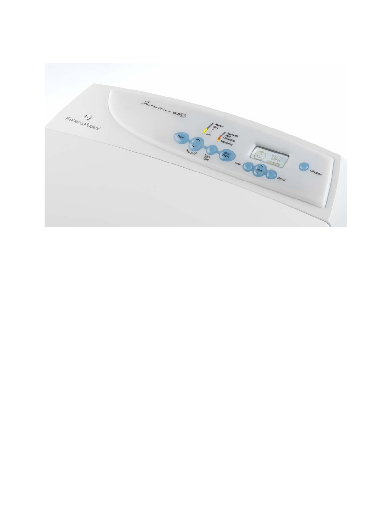
1.20 Control Panel – Intuitive Eco
7
Page 8

517793A
2 LID LOCK
The Phase 7 Intuitive Eco™ Washer uses the same lid lock
that is used on the Phase 6 series 11 & 12 machines. The
difference being is that the lid is now locked for the entire
cycle. A symbol of a padlock will be displayed on the when
the lid lock is activated. Once the spin has completed, the
lock will release and the lid can be opened. To open the lid
during the cycle the START/PAUSE button must be pressed,
the machine will come to a halt, and the padlock symbol will
disappear.
If the lid is left open, the machine will be unable to lock the lid
and the cycle will be halted. The machine will play a tune the
words “Please Close The Lid” will be displayed on the LCD
screen.
• If the lid-lock fails in the closed position, the locked lid can be forced upwards and out of the
lock. Note: This is the only time in which we would recommend doing this.
• If the harness is damaged, the complete lid lock assembly will need to be replaced.
If the power supply is cut during the spin cycle, the machine will keep the lid locked until the rotor
has ceased to turn (3 to 10 secs). Only then will it release the lock. The motor is acting like a
generator and allows the lock to stay energized under the bowls inertia.
The chart below shows the stages when the lid is locked.
In a brown out situation, the machine will restart at the start of whatever section of the cycle it was
on and continue the wash. The lid lock would then be reactivated if it happened to be on a spin
cycle.
3 SIZE SETTING
To set the size, turn the power on at the power
point and off at the console. Press and hold the
FABRIC CARE button, then press the POWER
button. This will present a set of options in the
LCD screen.
The LCD screen has within it a number of
options. Push the ADJUST button to highlight
650mm (L). Pushing the POWER button will
lock the “size” into the module’s memory.
4 DIAGNOSTIC MODE
The diagnostic mode incorporates both tests for the drain pump and the water valves, and also the
data display mode.
To enter the diagnostic mode, turn the power on at the power point and off at the console. Press
and hold the LIFECYCLES button and then the POWER button.
The machine will give 2 short beeps and the LCD screen will go blank. Then press OPTIONS for
data retrieval.
Note: Make sure that the buttons are released after the beeps, or the machine will turn itself
out of the diagnostic mode.
8
Page 9

517793A
4.1 Data Display
To enter the DATA DISPLAY screens, push the LIFECYCLES button again. This will enable the
out of balance switch to be tested, as well as giving access to the Detailed Fault Codes and User
Warning Faults. One of three displays will appear in the screen. Use the buttons on the bottom of
the display screen to toggle between these displays. Options, up or down.
The WARNING STATUS screen will display the
last USER WARNING FAULT that occurred and
will show at what part of the cycle it occurred.
The User Warning Faults are as follows:
• No Taps
• Overloaded
• Out Of Balance
• Over Suds or water still in the machine
during spin
• No Hot Water
• No Cold Water
• Agitate Overloaded
The MACHINE STATUS screen displays the
status of the diverter and the out of balance
switch. It also displays the size setting of the
machine, and the thermistor temperature.
HVDC is for on line testing in the factory.
Target temp is the temperature selected.
T is the actual temp of the inlet chamber water.
The FAULT STATUS screen will display a code
for the last fault that has occurred in the
machine. It will also display how many cycles
ago that the fault occurred, and at what part of
the cycle.
See Detailed Fault Codes for servicing tips.
Note: The fault code number can now be checked in the detail fault codes, to ascertain what
repairs may be necessary.
9
Page 10

517793A
4.2 Water Valve Test
When in diagnostic mode on IW machines, pressing the HOW DIRTY down button will turn the
Cold water valve on. Pressing the HOW DIRTY up button will turn the hot water valve on. You
need to hold the buttons down to keep the water entering the machine. This is also good to use
when installing machines as it takes the shock out of the fittings and seals and allows checking for
leaks on the inlet hoses, both machine end and tap or super-tub end.
Pressing each button once will activate the valve. To de-activate valve press the same button
again.
Caution: Do not leave the machine unattended when either or both valves are operating.
4.3 Drain Pump Test
When in diagnostic mode the FABRIC CARE button turns the drain pump on or off. This feature
can be helpful if the bowl is still full of water.
4.4 Restart Feature
The Restart feature on the Intuitive can be accessed when in diagnostic mode, pressing the
OPTIONS button will bring up the CONTROL OPTION screen. The LCD screen will display the
following:
The machine leaves the factory with the
RESTART set to the ON position (as shown
here), which is indicated in the screen by the
word RESTART highlighted. To turn the
RESTART feature OFF, push the HOME button.
This will remove the highlight from the word
RESTART. When the machine is being
serviced, it is more convenient to turn the
RESTART feature OFF. This will allow any fault
in the system to show up immediately.
With the RESTART feature on:
1. If a fault occurs in the machine, the diagnostic system will detect it. However, instead of
displaying a fault code immediately, the machine will try to RESTART.
2. If the fault was only of temporary nature, the machine will restart and finish the cycle.
3. If there is a continuous fault the machine will try to RESTART a number of times. This
process could take up to 8 minutes depending on the type of fault. After this, if the machine
still cannot restart, the fault code is displayed and the machine will beep continuously.
Whether or not the RESTART feature is on is indicated during normal use of the machine as
follows:
1. If none of the 5 green “HOW DIRTY” LED’s are on, the RESTART feature is on.
2. If the 5 green “HOW DIRTY” LED’s are flashing, the RESTART feature is off.
NOTE - This feature is designed as a service aid only and should be left ON in the customer’s
home. To return to normal operation, and to reset the RESTART feature to the factory setting,
switch the machine off at the wall or disconnect from the mains supply.
10
Page 11

517793A
4.5 Recycle Feature
In the Control Option mode (as for setting the RESTART feature), pushing the ADJUST button to
highlight the word RECYCLE will toggle this feature on and off. At the end of servicing, the
machine may require an extended test where the machine can be left to complete a number of
wash cycles. By turning on the RECYCLE feature the machine will continuously repeat the wash
cycle until the RECYCLE feature is turned off.
Whether or not the RECYCLE feature is on is indicated during normal use of the machine as
follows:
When the machine is first turned on:
1. If none of the FABRIC CARE LED’s are on, the recycle feature is off.
2. If all of the FABRIC CARE LED’s flash, the recycle feature is on.
NOTE: This feature is designed as a service aid only and should be OFF in the customer’s
home. To return to normal operation, and to return the recycle feature to the factory
setting, switch the machine off at the wall or disconnect from the mains supply.
4.6 Hot Bowl Flag
If the machine has been filled with the hot water
valve utilized (ie. warm or hot fill) and has not
had a cold rinse, the electronics will not allow
the machine to spin up to its full speed of 1000
RPM. It will only allow the spin speed to reach
700 RPM.
To remove this flag, enter the Control Option
mode and push the OPTIONS UP button to take
the black shading out of the box Hot Bowl Flag,
or put the machine through a complete final
rinse.
NOTE: The drain pump test, water valve test, restart, recycle and hot bowl flag features can
be accessed from any level in the diagnostic mode.
5 FAULT CODES
Fault codes for the Intuitive Eco™ washing machine are detailed in the master service manual, part
number 517792a.
11
Page 12

517793A
6 WIRING DIAGRAM
12
Page 13

517793A
7 REMOVAL OF DISPLAY MODULE
Note: Prior to carrying out any service procedures ensure that the power to the machine is
switched off.
7.1 Components In Console Area
(a) Remove the lid.
(b) Remove the two screws at the rear of the console securing the console to the top deck.
(c) Tilt the console forward.
7.2 Removal Of Display Module
(a) Disconnect the wiring harness from the
display module.
(b) Remove the 3 screws securing the display
module to the console
(c) Using a flat bladed screwdriver, push the
two top tabs that secure the display
module to the facia.
(d) When these tabs are clear, lift the right
hand end of the module and slide in the
direction shown.
Slide after clearing top tabs
13
Page 14

517793A
Notes
14
 Loading...