

Fisher & Paykel OS302US, OD302MNZ, OS302MNZ, OD302EU, OS302EU Service Manual
...
Model OD302 Model OS302
MODELS
OD302US OS302US
OD302MUS OS302MUS
OD302MNZ OS302MNZ
OD302EU OS302EU
546596A


Service Manual 546596A: 302 Series Titan Oven June 2005
Fisher & Paykel Appliances Ltd
78 Springs Road, East Tamaki, PO Box 58-732,
Greenmount,
Auckland, New Zealand
Ph: 09 273 0600, Fax: 09 273 0656
Fisher & Paykel Appliances Inc
5800 Skylab Road, Huntington Beach, California,
CA92647, USA
Ph: 888 936 7872 (F&P), Ph: 888 396 2665 (DCS)
Fisher & Paykel Customer Services Pty Ltd
A.C.N. 003 3335 171, 19 Enterprise Street, Cleveland,
QLD 4163
PO Box 798, Cleveland, QLD 4163
Ph: 07 3826 9100, Fax: 07 3826 9164
Fisher & Paykel Appliances Ltd UK
Pheasant Oak Barn, Hob Lane, Balsall Common,
Warwickshire, CV7 7GX, UK
Ph: 44 1676 531 770, Fax: 44 1676 531 771
Copyright Fisher & Paykel Ltd 2005. All Rights Reserved.
3
Manual 546596A – June 2005 Reprint: June 2005
The specifications and servicing procedures outlined in this manual are subject to change
without notice.
The latest version is indicated by the reprint date and letter and replaces any earlier editions.

Service Manual 546596A: 302 Series Titan Oven June 2005
4
Contents
1. SERVICING REQUIREMENTS......................................................................................................................................7
1.1 H
EALTH & SAFETY...........................................................................................................................................................7
1.1.1 Electrical Safety .....................................................................................................................................................7
1.1.2 Electrostatic Discharge..........................................................................................................................................7
1.1.3 Good Working Practices ........................................................................................................................................7
1.1.4 Insulation Test........................................................................................................................................................7
1.1.5 Sheet Metal Edges ..................................................................................................................................................7
1.2 S
PECIALISED TOOLS ......................................................................................................................................................... 8
1.2.1 Static Strap.............................................................................................................................................................8
1.2.2 Fisher & Paykel Smart Tool...................................................................................................................................8
2. TECHNICAL OVERVIEW...............................................................................................................................................9
2.1 O
VEN WEIGHTS ................................................................................................................................................................9
2.2 P
OWER RATING.................................................................................................................................................................9
2.3 O
VEN CAVITY DIMENSIONS..............................................................................................................................................9
2.4 L
OCATION OF SERIAL PLATE ............................................................................................................................................9
2.5 M
ODEL NUMBER ..............................................................................................................................................................9
2.6 S
ERIAL NUMBER .............................................................................................................................................................10
2.7 O
VEN CAVITY FAN (CONVECTION FAN) .........................................................................................................................11
2.8 C
OOLING FAN .................................................................................................................................................................11
2.9 A
CTIVE VENT FAN (EXHAUST FAN) ...............................................................................................................................12
2.10 O
UTER BROIL / GRILL ELEMENT.....................................................................................................................................12
2.11 I
NNER BROIL / GRILL ELEMENT......................................................................................................................................13
2.12 B
AKE ELEMENT ..............................................................................................................................................................13
2.13 F
AN ELEMENT.................................................................................................................................................................13
2.14 S
MOKE ELIMINATOR ELEMENT (CATALYTIC CONVERTER).............................................................................................14
2.15 T
HROAT ELEMENT ..........................................................................................................................................................14
2.16 T
EMPERATURE SENSOR...................................................................................................................................................14
2.17 H
ALOGEN BULBS ............................................................................................................................................................14
2.18 M
EAT PROBE & SOCKET................................................................................................................................................. 15
2.19 D
OOR LOCK MOTOR .......................................................................................................................................................15
2.20 T
EMPERATURE SWITCH MODULE....................................................................................................................................15
2.21 T
EMPERATURE L.C.D MODULE ......................................................................................................................................15
2.22 F
UNCTION SWITCH MODULE...........................................................................................................................................15
2.23 F
UNCTION L.C.D MODULE .............................................................................................................................................15
2.24 C
LOCK MODULE .............................................................................................................................................................16
2.25 P
OWER MODULE .............................................................................................................................................................16
2.26 P
OWER TRANSFORMER ...................................................................................................................................................16
2.27 C
OOLING FAN RESISTOR.................................................................................................................................................17
2.28 T
HERMAL LIMITERS........................................................................................................................................................ 17
2.29 I
SOLATING RELAY .......................................................................................................................................................... 19
2.30 XY-C
APACITOR ..............................................................................................................................................................19
2.31 M
ICRO SWITCHES ...........................................................................................................................................................19
2.32 S
ELF-CLEAN PYROLYTIC CYCLE.....................................................................................................................................20
2.33 O
VEN MODE ELEMENT AND FAN PROFILES ....................................................................................................................21
3. USE & CARE OF THE OVEN........................................................................................................................................22
3.1 S
ETTING THE CLOCK.......................................................................................................................................................22
3.2 O
VEN MODE DIAL AND DISPLAY....................................................................................................................................22
3.3 T
EMPERATURE DIAL AND DISPLAY ................................................................................................................................22
3.4 O
VEN MODES .................................................................................................................................................................22
3.5 A
CTIVE VENT AND COOLING FANS.................................................................................................................................23
3.6 M
INUTE TIMER ...............................................................................................................................................................24
3.7 S
ET AUTOMATIC / DELAYED TIME COOKING .................................................................................................................24
3.8 S
ET AUTOMATIC STOP COOKING....................................................................................................................................25
3.9 U
SER SELECT MODES .....................................................................................................................................................25
3.10 S
ABBATH MODE .............................................................................................................................................................25
3.11 T
EMPERATURE SCALE..................................................................................................................................................... 26

Service Manual 546596A: 302 Series Titan Oven June 2005
5
3.12 SHORT ALERT .................................................................................................................................................................26
3.13 T
IME MODE ....................................................................................................................................................................26
3.14 S
HOW CLOCK.................................................................................................................................................................. 26
3.15 L
ANGUAGE .....................................................................................................................................................................27
3.16 O
VEN RESET ...................................................................................................................................................................27
4. DIAGNOSTICS ................................................................................................................................................................28
4.1 E
NTERING THE SALES MODE & TECHNICIAN MODE.......................................................................................................28
4.2 E
XITING THE TECHNICIAN MODE....................................................................................................................................28
4.3 T
ECHNICIAN MODE NAVIGATION ...................................................................................................................................28
4.4 A
CCESSING TECHNICAL DATA LOG ................................................................................................................................30
4.5 T
ECHNICAL DATA LOG ...................................................................................................................................................30
5. FAULT DIAGNOSTICS.................................................................................................................................................. 31
5.1 SYMPTOM: O
VEN ELECTRICAL COMPONENTS ARE UNRESPONSIVE ..............................................................................31
5.2 SYMPTOM: C
ONTROL BUTTONS OR CLOCK DISPLAY NOT OPERATING CORRECTLY OR UNRESPONSIVE.......................32
5.3 SYMPTOM: T
EMPERATURE OR OVEN MODE SWITCH MODULE IS JAMMED OR LOOSE .................................................32
5.4 SYMPTOM: I
NCORRECT TEMPERATURE OR OVEN MODE DISPLAY AT CORRECT SWITCH POSITION ..............................32
5.5 SYMPTOM: F
AULTY TEMPERATURE OR OVEN MODE L.C.D. MODULES .....................................................................33
5.6 SYMPTOM: “DOORLOCK”
AND “PROBE” SHOWING FOR LOWER CAVITY (DOUBLE OVEN ONLY) ............................33
5.7 SYMPTOM: O
VEN UNDER COOKING ............................................................................................................................34
5.8 SYMPTOM: B
AKING BURNS ON THE TOP ......................................................................................................................34
5.9 SYMPTOM: B
AKING BURNS ON THE BOTTOM ...............................................................................................................35
5.10 SYMPTOM: O
VEN SEEMS TO BE FUNCTIONING NORMALLY BUT DOES NOT HEAT..........................................................35
5.11 SYMPTOM: O
VEN HEATS SLOWLY OR FAILS TO REACH PRESET TEMPERATURE ............................................................36
5.12 SYMPTOM: O
VEN LIGHTS DO NOT TURN ON / OFF.......................................................................................................36
5.13 SYMPTOM: F
AULT CODE F1 DISPLAYED IN TECH SELECT ONLY .................................................................................37
5.14 SYMPTOM: F
AULT CODE F2 DISPLAYED......................................................................................................................37
5.15 SYMPTOM: F
AULT CODE F3 DISPLAYED......................................................................................................................37
5.16 SYMPTOM: F
AULT CODE F4 DISPLAYED......................................................................................................................37
5.17 SYMPTOM: F
AULT CODE F5 DISPLAYED......................................................................................................................38
5.18 SYMPTOM: F
AULT CODE F7 DISPLAYED......................................................................................................................38
5.19 T
RACING COOLING FAN FAULTS.....................................................................................................................................38
5.20 T
RACING OVEN CAVITY FAN FAULTS...............................................................................................................................39
5.21 T
RACING OVEN LIGHT FAULTS ........................................................................................................................................39
5.22 T
RACING ELEMENT FAULTS.............................................................................................................................................40
5.23 T
RACING OVEN TEMPERATURE SENSOR FAULTS..............................................................................................................41
5.24 T
RACING THERMAL LIMITER FAULTS .............................................................................................................................. 41
5.25 T
RACING OVEN DOOR SWITCH AND DOOR LOCK SWITCH FAULTS ....................................................................................42
5.26 D
ETERMINING WHICH POWER MODULE IS FAULTY IN A DOUBLE OVEN (F4 OR F5 FAULT CODES) ..................................43
6. WIRING DIAGRAMS .....................................................................................................................................................44
6.1 D
OUBLE OVEN USA WIRING SCHEMATIC ......................................................................................................................44
6.2 S
INGLE OVEN USA WIRING SCHEMATIC........................................................................................................................45
6.3 D
OUBLE OVEN NZ / AUS WIRING SCHEMATIC .............................................................................................................46
6.4 S
INGLE OVEN NZ / AUS WIRING SCHEMATIC ...............................................................................................................47
6.5 D
OUBLE OVEN EU WIRING SCHEMATIC.........................................................................................................................48
6.6 S
INGLE OVEN EU WIRING SCHEMATIC ..........................................................................................................................49
7. SERVICE PROCEDURES ..............................................................................................................................................50
7.1 R
EMOVAL FROM JOINERY CAVITY..................................................................................................................................50
7.2 C
OMPONENTS IN CONTROL PANEL AREA .......................................................................................................................50
7.3 C
OMPONENTS IN BACK PANEL AREA..............................................................................................................................51
7.4 C
OMPONENTS IN SERVICE PANEL AREA .........................................................................................................................51
7.5 R
EASSEMBLY PROCEDURE..............................................................................................................................................51
7.6 F
UNCTION AND TEMPERATURE SWITCH MODULES.........................................................................................................52
7.7 F
UNCTION AND TEMPERATURE L.C.D. MODULES AND LENSES .....................................................................................52
7.8 C
LOCK MODULE OR BUTTONS ........................................................................................................................................53
7.9 P
OWER MODULE.............................................................................................................................................................54
7.10 P
OWER TRANSFORMER ...................................................................................................................................................57
7.11 T
HERMAL LIMITER..........................................................................................................................................................57
7.12 O
VEN TEMPERATURE SENSOR ........................................................................................................................................57
7.13 O
VEN LAMP GLASS AND BULB .......................................................................................................................................58
7.14 O
VEN LAMP ASSEMBLY ..................................................................................................................................................58

Service Manual 546596A: 302 Series Titan Oven June 2005
6
7.15 OVEN ELEMENTS ............................................................................................................................................................60
7.16 C
OOLING FAN .................................................................................................................................................................62
7.17 V
ENT FAN .......................................................................................................................................................................62
7.18 O
VEN CAVITY FAN .........................................................................................................................................................63
7.19 F
AN SHROUD...................................................................................................................................................................63
7.20 R
UNNERS ........................................................................................................................................................................64
7.21 O
VEN DOOR....................................................................................................................................................................64
7.22 O
VEN DOOR – DISASSEMBLY .........................................................................................................................................64
7.23 M
EAT PROBE SOCKET.....................................................................................................................................................67
7.24 O
VEN DOOR LOCK ASSEMBLY........................................................................................................................................68
7.25 C
OMPONENT LOCATION GUIDE.......................................................................................................................................69
Service Manual 546596A: 302 Series Titan Oven June 2005
7
1. Servicing Requirements
1.1 Health & Safety
Note: When servicing the Titan Aerotech oven, health and safety issues must be
considered at all times. Specific safety issues are listed below with their appropriate
icon. These are illustrated throughout the service information to remind service people of
the health and safety issues.
1.1.1 Electrical Safety
WARNING! TO AVOID ELECTRIC SHOCK!
Do not attempt to service this oven without suitable training and
qualifications.
Ensure the mains power has been disconnected before servicing any part of the oven. If
the power is required to be on for electrical fault finding, then extreme care should be
taken not to make contact with electrical components other than with testing probes.
Ensure the oven is turned off when removing any electrical component or connection.
1.1.2 Electrostatic Discharge
An anti-static strap is to be used as electrical static discharge (ESD)
protection when servicing electronic components.
1.1.3 Good Working Practices
Ensure the work areas are kept tidy and free of hazards while servicing the
oven. On completion of the servicing, ensure the oven and work areas are
left clean and tidy.
1.1.4 Insulation Test
Megger test to check insulation.
Warning Short together the phase and neutral terminals to avoid damaging
any electronic circuitry.
1.1.5 Sheet Metal Edges
When working around cut sheet metal edges use appropriate gloves or
protection to eliminate the chance of receiving a laceration.

Service Manual 546596A: 302 Series Titan Oven June 2005
8
1.2 Specialised Tools
1.2.1 Static Strap
The static strap is to be used as E.S.D. protection when replacing or handling electronic
components.
1.2.2 Fisher & Paykel Smart Tool
Handheld computer supplied in protective case with F&P diagnostics software and
service information loaded:
P/N 813140 (includes light pen P/N 425930).
Service Manual 546596A: 302 Series Titan Oven June 2005
9
2. Technical Overview
2.1 Oven Weights
OS302 Weight: 190 lbs. (86 Kg)
OD302 Weight: 340 lbs. (154 Kg)
2.2 Power Rating
Single Supply
Voltage
Rating Double Supply
Voltage
Rating
USA / Can
3wire 120/240v 5.1kW 3wire 120/240v 9.2kW
USA / Can
120/208v 3.9kW 120/208v 7kW
NZ / AUS
220/240v 4.7kW 220/240v 8.5kW
EU
220/240V 4.7kW 220/240V 7.6kW
2.3 Oven Cavity Dimensions
Width 24” (610mm)
Height 16” (405mm)
Depth 16” (405mm)
Cavity Volume 3.5 cu ft (0.1 m3)
2.4 Location of Serial Plate
The product serial plate is located on the left-hand side behind the grill, between the
control panel and the oven door (top oven door on dual oven models).
2.5 Model Number
The model number contains the following information:
OD30 2 M
Finish (M = Iridium)
Series
Product Width (inches)
Single or Double Oven
Product Type (Oven)

Service Manual 546596A: 302 Series Titan Oven June 2005
10
2.6 Serial Number
The serial number consists of three letters and six digits and contains the following
information:
Example:
MI M 123456
Sequential Serial Number
Manufacturing Plant Code
FISHERPAYKUL Code indicates month of manufacture
CUMBERLAND Code indicates year of manufacture
Cumberland Code
LetterCUMBERL AND
Year1234567890
Fisherpaykul Code
LetterFI SHERPAYKUL
Month123456789101112
Manufacturing Plant Code
A Laundry – Australia
F Refrigeration – New Zealand
M Range & Dishwasher
N Laundry – New Zealand
Q Refrigeration - Australia
In the example above, the appliance was manufactured in the second month of the third
year (2003) at the Range & Dishwasher plant.

Service Manual 546596A: 302 Series Titan Oven June 2005
11
2.7 Oven Cavity Fan (Convection Fan)
The oven cavity fan will turn on eight seconds after a mode is selected.
The fan should always operate when the fan element is on.
Operational Modes: True Aero
Aero Bake
Aero Pastry
Aero Broil / Grill
Roast (first 20 minutes only)
Warm
Bake (pre-heat assistance only)
Pastry Bake (pre-heat assistance only)
Voltage: 240
VAC
Wattage: 35 watts
Frequency: 60 HZ
2.8 Cooling Fan
The cooling fan will turn on as soon as the oven mode is moved from the ‘OFF ‘
position. It will turn off after eight seconds if a temperature isn’t selected.
The cooling fan will only turn off if the oven cavity has cooled below 300°F (150°C)
after use.
If the oven cavity temperature is above 550°F (290°C) the cooling fan will run at high
speed.
During the Self-Clean Cycle the cooling fan in the cavity being cleaned will run at high
speed, the other cavity will run on low (in a double oven).
NZ/AUS/EU U.S
Voltage: 230/240 VAC 115/120 VAC
Frequency: 50/60 HZ 60 HZ
Wattage: 60 watt 56 watt
Service Manual 546596A: 302 Series Titan Oven June 2005
12
Cooling Fan Speeds*
Oven Mode
Cooling Fan
Speed
Bake
Low
Low
Aero Bake
Low
Low
Warm
Low
Low
True Aero
Low
Low
Maxi Broil / Grill
Hi
Low
Broil / Grill
Hi
Low
Aero Broil / Grill
Hi
Low
Pastry Bake
Low
Low
Aero Pastry
Low
Low
Roast
(Aero Broil / Grill 1
st
20 min)
Hi
Low
Roast
(Bake for remainder)
Low
Low
Self-Clean Cycle
Hi
Low
*The top speed refers to single ovens or the
cavity being used in a double oven.
2.9 Active Vent Fan (Exhaust Fan)
The vent fan will operate for the first thirteen minutes of all oven modes except Warm
(does not operate) and Self-Clean Cycle, Broil / Grill modes (runs continuously).
Voltage: 230/240 VAC
Frequency: 50/60 HZ
Wattage: 18 watt
2.10 Outer Broil / Grill Element
The outer broil / grill element will turn on eight seconds after a mode is selected.
Operational Modes: Bake
Aero Bake
Warm
Maxi Broil / Grill
Aero Broil / Grill
Roast
Self-Clean
Voltage: 230/240 VAC
Wattage: 1500 watt

Service Manual 546596A: 302 Series Titan Oven June 2005
13
2.11 Inner Broil / Grill Element
The inner broil / grill element will turn on eight seconds after a mode is selected.
Operational Modes: Broil / Grill
Maxi Broil / Grill
Aero Broil / Grill
Roast (first 20 minutes only)
Self-Clean
Voltage: 230/240
VAC
Wattage: 2900 watt
2.12 Bake Element
The bake element is concealed under the cavity base and will turn on eight seconds after
a mode is selected.
Operational Modes: True Aero (pre-heat assistance only)
Bake
Aero Bake
Warm
Pastry Bake
Aero Pastry
Roast
Self-Clean
Voltage: 230/240
VAC
Wattage: 1500 watt
2.13 Fan Element
The fan element and oven fan will turn on eight seconds after a mode is selected.
Operational Modes: True Aero
Bake (pre-heat assistance only)
Aero Bake
Aero Pastry (pre-heat assistance only)
Pastry Bake (pre-heat assistance only)
Voltage: 230/240 VAC
Wattage: 2500 watt

Service Manual 546596A: 302 Series Titan Oven June 2005
14
2.14 Smoke Eliminator Element (Catalytic Converter)
(This is a non-serviceable part)
The smoke eliminator element is designed to neutralise gases produced during cooking.
Operational Modes: Broil / Grill
Aero Broil / Grill
Maxi Broil / Grill
Self clean
Bake
Aero Bake
Pastry Bake
Aero Pastry
Roast
True Aero
Voltage: 230/240 VAC
Wattage: 150 watt
2.15 Throat Element
(This is a non-serviceable part)
The throat element is designed to ensure all parts near the front of the oven cavity reach
the required temperatures during the Self-Clean Cycle.
Operational Modes: Self-Clean
Voltage: 230/240 VAC
Wattage: 540 watt
2.16 Temperature Sensor
Voltage: 5 VDC
Max current: 2 mA
Max ambient temp: 1000°F (540°C)
Resistance: 1080.2 ohms +/– 5.2 ohms at 70°F (21.11°C)
2.17 Halogen Bulbs
The oven cavity lights will come on when the door is opened or when an oven mode
is selected.
The lights will turn off when the door is closed (if no oven mode is selected) or if the
programmed oven cook time has finished.
There are three soft start halogen bulbs in each oven cavity.
Voltage: 12 VAC
Wattage: 20 watt

Service Manual 546596A: 302 Series Titan Oven June 2005
15
2.18 Meat Probe & Socket
Voltage: 5 VDC
Figure 2.18
2.19 Door Lock Motor
The door lock will only operate during the Self-Clean Cycle and is designed to stop the
oven door being opened when very high temperatures and potentially dangerous fumes
are produced in the oven cavity.
Voltage: 12
VDC
Duty cycle: On 2 sec Off 5 sec
Stall current: under 0.5 Amp
2.20 Temperature Switch Module
The temperature switch module controls the
temperature settings of the oven. It has a data link
to the clock module.
Current Draw: 72 mA
Figure 2.20
2.21 Temperature L.C.D Module
The temperature LCD module is controlled by the
clock module. It displays the temperature set by the
temperature switch module.
Current Draw: 72 mA
Figure 2.21
2.22 Function Switch Module
The function switch module sets the oven mode to
be used. It has a data link to the clock module.
Current Draw: 72 mA
Figure 2.22
2.23 Function L.C.D Module
The function LCD module is controlled by the clock
module. It displays the oven mode selected by the
function switch module.
Current Draw: 72 mA
Figure 2.23

Service Manual 546596A: 302 Series Titan Oven June 2005
16
2.24 Clock Module
The clock module contains a flash micro-controller that
controls all oven electrical components. Data can be
accessed from the micro-controller using the Fisher &
Paykel Smart Tool light pen or comms. connection.
Current Draw: 200 mA
Figure 2.24
2.25 Power Module
Figure 2.25
The power module is a Fisher & Paykel specific P.C.B. that drives oven lights, fans,
elements and lock motors. It also monitors the sensors and micro-switches and provides
power to the control panel.
Voltage: 12 VAC
2.26 Power Transformer
USA 12v/120v 60hz
NZ/AUS/EU 12v/240v 50hz

Service Manual 546596A: 302 Series Titan Oven June 2005
17
2.27 Cooling Fan Resistor
Power Rating: 50 watt
Resistance: 220 Ohms
Max Ambient Temp: 85°C (185°F)
2.28 Thermal Limiters
If a thermal limiter has tripped there will be no continuity across the contacts.
Limiter Locations for US/NZ/AUS Products
TL1
TL2
MTL
Figure 2.28a
Note: TL = Thermal Limiter
MTL = Microtemp limiter
Double ovens have thermal limiters 1,2 & 3
and a microtemp limiter.
Single ovens have thermal limiter 1 and a
microtemp limiter.
TL3
Figure 2.28b

Service Manual 546596A: 302 Series Titan Oven June 2005
18
Limiter Locations for EU Products
TL4
TL1
MTL
Figure 2.28c
Note: TL = Thermal Limiter
MTL = Microtemp thermal limiter
Double ovens have thermal limiters 1, 3, 4
& 5 and a microtemp limiter.
Single ovens have thermal limiters 1 & 4
and a microtemp limiter.
TL3
TL5
Figure 2.28d
MTL (Microtemp Limiter)
This is a non-resettable thermal limiter positioned to detect
electronics area over temperature caused by a cooling fan
failure. It will cut power to the power transformers,
disabling the oven when tripped.
Capacity Rating: 25 Amps at 240
VAC.
Trip Temperatures: 200°F (93°C)
Figure 2.28e
TL 1 & TL 2
These are non-resettable thermal limiters positioned to
detect the upper cooling fan failure on a double oven. They
will cut power to the oven elements when tripped.
Capacity Rating: 25 Amps at 240 VAC.
Trip Temperatures: 175°F (80°C)
Figure 2.28f
TL 3
This is a non-resettable thermal limiter positioned to detect lower cooling fan failure on a double
oven. It will cut power to the oven elements when tripped.
Capacity Rating: 25 Amps at 240 VAC.
Trip Temperatures: 230°F (110°C)

Service Manual 546596A: 302 Series Titan Oven June 2005
19
TL 4 (EU Products Only)
This is a resettable thermal limiter positioned to detect the
upper cooling fan failure on a double oven. It will cut power
to the oven elements when tripped.
Capacity Rating: 16 Amps at 250 VAC.
Trip Temperatures: 175°F (80°C)
Figure 2.28g
TL 5 (EU Products Only)
This is a resettable thermal limiter positioned to detect lower cooling fan failure.
It will cut power to the oven elements when tripped.
Capacity Rating: 16 Amps at 250 VAC.
Trip Temperatures: 230°F (110°C)
2.29 Isolating Relay
(Double Line Break Relay)
This relay switches the elements, cavity fan and vent
fan on the opposite side to the power module relay
switches.
It is only energised when an oven mode is selected.
Coil Voltage: 12 VDC
Coil Input: 1 watt
Figure 2.29
2.30 XY-Capacitor
This capacitor provides surge protection for the oven.
Voltage: 250 VAC
Class: X2Y2
Temp Range: -105 to 210°F (- 40 to 100°C)
2.31 Micro Switches
There are three micro switches in the door lock assembly.
Voltage 12 VDC

Service Manual 546596A: 302 Series Titan Oven June 2005
20
2.32 Self-Clean Pyrolytic Cycle
Duration: 3hrs
Pyro Temp: 925°F (500°C)
Heat-up time: 50 minutes approx.
Holding time: 100 minutes approx.
Cool-down time: 30 minutes
If a Self-Clean Cycle will not start, check that there are no meat probes inserted and that
the control knobs of the cavity not being cleaned (in a double oven) are in the ‘OFF’
position.
The oven self-clean mode operates by heating the oven to a temperature of
approximately 885°F (473°C). This burns off and breaks down soil and grease deposits.
The ash residue that remains can simply be removed from the cool oven with a damp
cloth or sponge. The self-clean cycle normally takes about three hours.
To start a Self-Clean Cycle
1. Turn the oven mode dial until ‘Self Clean’ appears in the display.
2. Select the maximum temperature using the temperature dial.
‘000’ will appear in the temperature display. This will change to when the
cycle begins.
‘Door Lock’ and ‘Clean’ will show in the clock display.
The door lock will automatically activate once the Self-Clean mode and maximum
temperature have been selected.
A countdown of minutes remaining will be shown in the clock display.
The Broil / Grill inner element, the throat element, the smoke eliminator element and the
vent fan operate during the Self-Clean Cycle. Additionally, during the first fifteen seconds
of each minute the bake element is on and during the third fifteen seconds of each
minute the Broil / Grill outer element is on.
The cooling fan for the cavity being cleaned will be on high speed. The cooling fan for
the other cavity will be on low speed.
During the Self-Clean Cycle in a double oven, the cavity not being cleaned cannot be
operated in any mode.
The oven heats to its cleaning temperature of 885°F (473°C) and maintains this
temperature until approximately 2½ hours into the cycle.
The elements then turn off and the cool down period commences. When the
temperature reduces to 356°F (180°C) the door will unlock and the ‘Door Lock’ display
will disappear from the clock display.
When the self-clean cycle has finished, ‘Clean’ and ‘00:00’ will flash in the clock display
until it is returned to manual operation. Press the PUSH TO CLEAR button and turn the
oven mode and temperature dials to the OFF position to do this.
At the completion of the self-clean cycle, there may be grey ash deposited on the inside
of the oven. The amount of ash is dependent on the amount of soil in the oven before
cleaning. To remove the ash, wait until the oven has completely cooled. The bulk of the
ash is easily removed with a small brush or dry cloth, then wiped over with a damp cloth.
The self-clean mode can be cancelled at any time by turning the oven dials to ‘OFF’.
‘Clean End’ will appear in the oven mode display but if the oven temperature has already
reached 482°F (250°C) the door lock will remain activated until the oven cools to 356°F
(180°C).

Service Manual 546596A: 302 Series Titan Oven June 2005
21
2.33 Oven Mode Element and Fan Profiles
If the oven door is opened during use the oven fan and elements will turn off until it is
closed again.
Oven
Mode
Name
Oven
Fan
Cool
Fan
Speed
Vent
Fan
Broil/Grill
Outer
Element
Broil/Grill
Inner
Element
Bake
Element
Fan
Element
Throat
Element
Smoke
Elim.
Bake
(on for
pre-heat
only)
Low
Low
(on for first
13 mins)
ON ON
(on for pre-
heat only)
ON
Aero
Bake
ON
Low
Low
(on for first
13 mins)
ON ON ON ON
Warm ON
Low
Low
ON ON
True
Aero
ON
Low
Low
(on for first
13 mins)
(on for pre-
heat only)
ON ON
Maxi
Broil/Grill
OFF
Hi
Low
ON ON ON ON
Broil/Grill OFF
Hi
Low
ON ON ON
Aero
Broil/Grill
ON
Hi
Low
ON ON ON ON
Pastry
Bake
(on for
pre-heat
only)
Low
Low
(on for first
13 mins)
ON
(on for pre-
heat only)
ON
Aero
Pastry
ON
Low
Low
(on for first
13 mins)
ON
(on for pre-
heat only)
ON
Roast
(Aero
Broil/Grill 1
st
20Min)
ON
Hi
Low
(on for first
13 mins)
ON
(on for first
20 mins)
ON
Roast
(Bake for
remainder)
OFF
Low
Low
(on for first
13 mins)
ON ON ON
Heating Profile for Self-Clean Pyrolitic Cycle
Self Clean
(0-15sec)
OFF
Hi
Low
ON ON ON ON ON
(15-30sec)
OFF
Hi
Low
ON ON ON ON
(30-45sec)
OFF
Hi
Low
ON ON ON ON ON
(45-60sec)
OFF
Hi
Low
ON ON ON ON
Service Manual 546596A: 302 Series Titan Oven June 2005
22
3. Use & Care of the oven
3.1 Setting the Clock
The clock has a default 12 hour display and a minute timer function. ‘AM 12:00’ will show
and the colon will flash when the oven has been turned on at the wall. While the colon is
flashing, rotate the PUSH TO CLEAR knob until the correct time of day is displayed.
Press CLOCK or wait 8 seconds until the colon stops flashing to adopt the time that has
been set.
3.2 Oven Mode Dial and Display
This is turned to select the desired oven mode. When the mode is set the lights and
cooling fan will come on.
3.3 Temperature Dial and Display
This is turned to select the desired temperature.
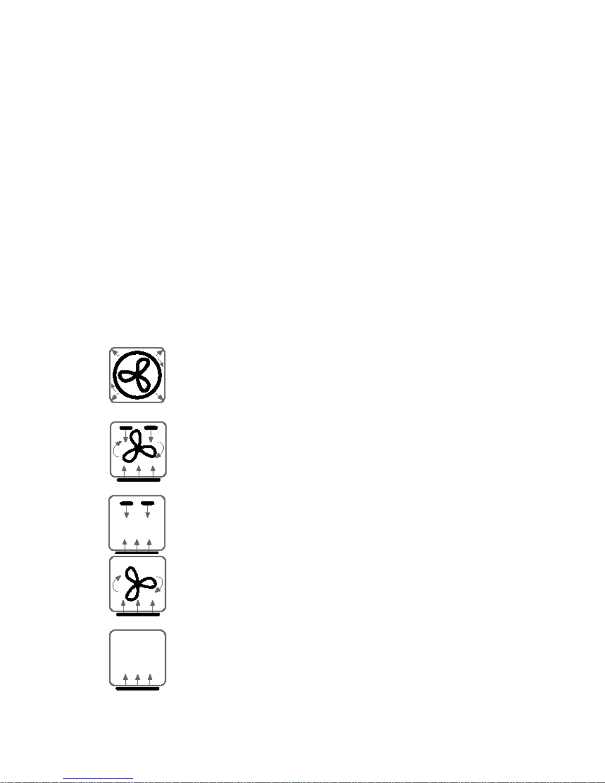
3.4 Oven Modes
The oven has 9 cooking modes plus Warm and Self Clean. These use different
combinations of elements and the oven fan as follows:
• True Aero. A concealed heating element surrounding the fan in
the rear of the oven heats air, which is then blown into the oven
cavity.
• Aero Bake. The oven fan circulates hot air from the upper outer
and the bake elements.
• Bake. Heat comes from the upper outer and the bake elements.
• Aero Pastry. Heat comes from the bake element and is
circulated throughout the oven cavity by the oven fan.
• Pastry Bake. Uses the heat from the bake element only.
 Loading...