

Page 1

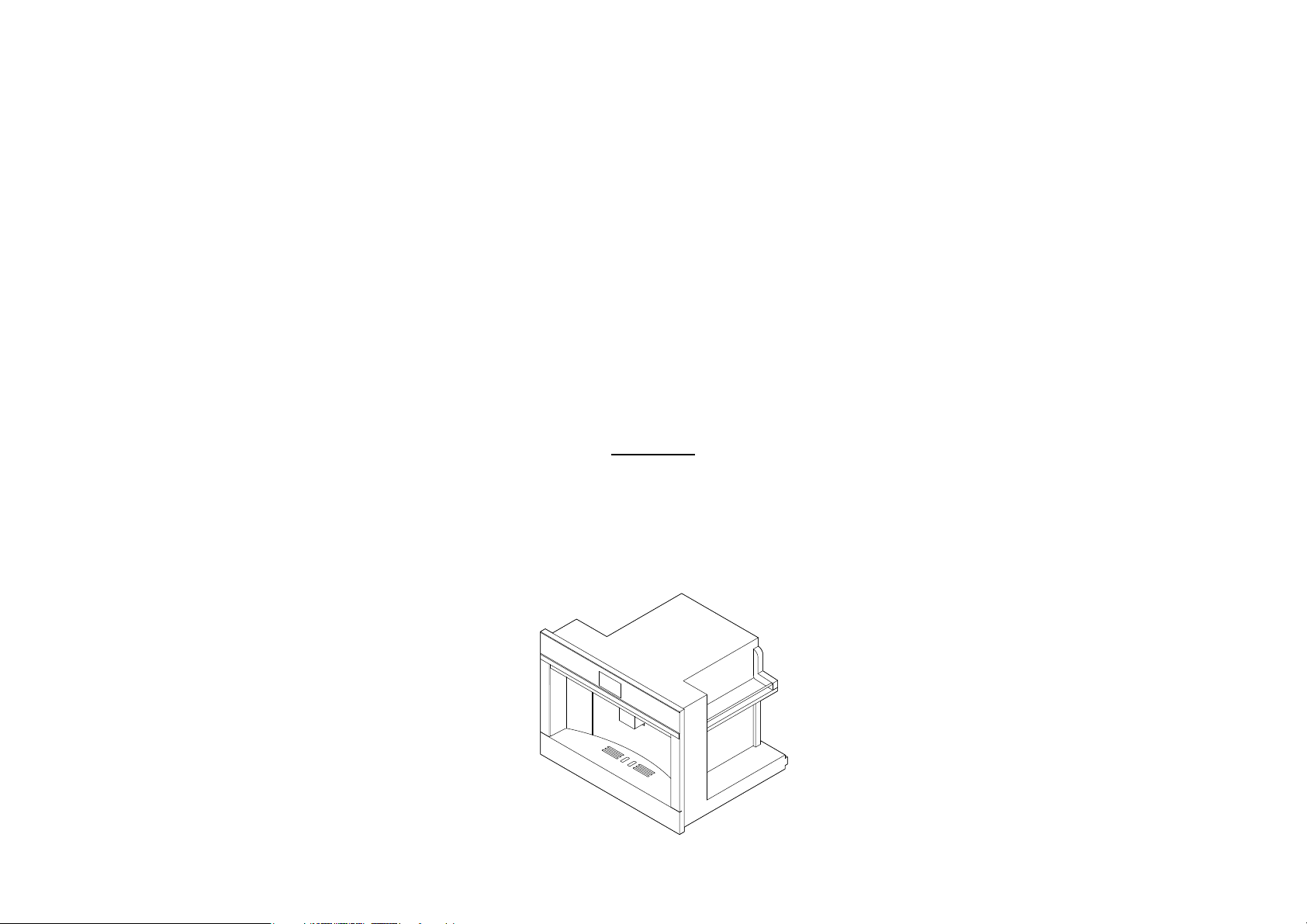
COMPANION PRODUCTS
Co ee Maker EB60
Steam Oven OS60
Microwave Oven OM60
models
INSTALLATION GUIDE
NZ AU GB IE
Page 2

CONTENTS
Coffee maker 13
1 Safety and warnings 1
2 Parts supplied 2
3 Prior to installation 3
4 After installation 3
5 Product dimensions 4
6A Cabinetry dimensions
(460mm high cavity) 5
6B Cabinetry dimensions
(480mm cavity trim kit) 6
7 Installation instructions 7
8 Final checklist 8
Steam oven 9
1 Safety and warnings 10
2 Parts supplied 11
3 Prior to installation 11
4 After installation 12
5 Product dimensions 13
6A Cabinetry dimensions
(460mm high cavity) 14
6B Cabinetry dimensions
(480mm cavity trim kit) 15
7 Installation instructions 15
8 Final checklist 16
Microwave oven 17
1 Safety and warnings 18
2 Prior to installation 19
3 After installation 19
4 Product dimensions 20
5A Cabinetry dimensions
(460mm high cavity) 21
5B Cabinetry dimensions
(480mm cavity trim kit) 22
6 Electrical hook-up 23
7 Secure the oven to the cabinetry 23
8 Final checklist 24
IMPORTANT!
SAVE THESE INSTRUCTIONS
The models shown in this user guide may not be available in all markets and are subject to change at any time. For current details about model and specification availability in your country,
please go to our website fisherpaykel.com or contact your local Fisher & Paykel dealer.
Page 3
COFFEE MAKER
EB60 models
Page 4
1SAFETY AND WARNINGS
IMPORTANT SAFETY INSTRUCTIONS!
Installation
WARNING!
Cut Hazard
Take care – some edges are sharp.
Failure to use caution could result in injury or cuts.
Checking for transport damage
After removing the packaging, make sure the product is complete and undamaged and that all
accessories are present. Do not use the appliance if it is visibly damaged. Contact Customer Care.
IMPORTANT!
●
Installation must be performed by a qualified professional in compliance with legislation
in force in the country of installation.
●
Never install the appliance in rooms where the temperature may drop to 0°C or lower.
●
This appliance can be installed over a built-in oven if the latter is fitted with a cooling fan
at the rear (maximum microwave power: 3 kW).
●
Ensure the appliance is fully secured. Failure to do so may result in an unstable product,
which may cause damage or injury.
●
Connect to a properly rated, protected and sized power supply circuit to avoid electrical overload.
●
Make sure that the power supply cord is located so that it will not be stepped on, tripped
over or otherwise subject to damage or stress.
Connecting the appliance
This appliance should be connected to a circuit which incorporates an isolation switch providing
full disconnection from the power supply.
DANGER!
●
Check that the mains power supply voltage corresponds to the value indicated on the rating
plate on the bottom of the appliance.
●
Connect the appliance to an efficiently earthed and correctly installed socket with a minimum
current rating of 10A only.
●
If the power socket does not match the plug on the appliance, have the socket replaced
with a suitable type by a qualified professional.
●
To comply with safety directives, an omnipolar switch with a minimum contact distance
of 3mm must be installed.
●
Do not use multiple sockets or extensions.
●
Safety cutout devices must be included in the mains power supply in compliance with
the installation regulations in the country concerned.
●
This appliance conforms to EC Regulation 1935/2004 on materials and articles intended
to come into contact with food.
MAINTENANCE
●
Do not repair or replace any part of the appliance or attempt any servicing unless
specifically recommended in this user guide.
●
We recommend that you contact Customer Care to arrange service. See your ‘Service
and warranty’ booklet for contact details.
●
To prevent damage to the appliance do not use alkaline cleaning agents when cleaning,
use a soft cloth and a mild detergent.
●
If the plug or power cable is damaged, it must be replaced by an authorised technical
only to avoid all risk.
●
Appliances with removable cord: avoid splashes of water on the power cord connector
or socket at the back of the appliance.
●
Do not place weight onto the coffee machine when it is out of the cabinet.
●
Do not rest containers with liquids or inflammable or corrosive materials on top of
the appliance.
●
Do not rest large objects which could obstruct movement or unstable objects on
the appliance.
●
Never turn off the machine during descaling.
●
The first time you use the appliance, or if it is not used for more than three or four days, rinse
all removable accessories which may come into contact with water or milk with hot water.
●
If the appliance is not used for more than three or four days, prior to re-using the
appliance, rinse the water circuit as described in this manual.
●
You should diligently carry out automatic cleaning and guided maintenance when
prompted by the appliance through the display as described in this manual.
●
Choking hazard. The appliance might contain small parts. Some of those small partsmight
be required to get disassembled during cleaning and maintenance operations.
●
Handle with care and keep small parts out of reach of children.
●
Cleaning and user maintenance shall not be made by children without supervision.
Disposal
The appliance must not be disposed of with household waste, but taken to an authorised
waste separation and recycling centre.
Operational
●
Customise the water hardness as soon as possible following the instructions in the
‘Water hardness’ section.
●
Keep hands clear of the coffee spout when in operation. The temperature of liquid that
flows from the spout could result in burns.
●
During the rinse cycle hot water flows from the spout. Please keep hands clear of the
spout to avoid the risk of burns.
●
This appliance produces hot water and steam may form while it is in operation.
●
Models with glass surfaces: do not use the appliance if the surface is cracked.
●
Do not use the appliance when it is out the cabinet. Make sure the appliance is turned off
before extracting it. The only exception is adjusting the coffee mill which must be done
with the machine extracted (see section ‘Adjusting the coffee mill’).
Note: use original or manufacturer recommended accessories and spare parts only.
IMPORTANT!
SAVE THESE INSTRUCTIONS
The models shown in this installation guide may not be available in all markets and are subject to change at any time. For current details about model and specification availability in your country,
please go to our website fisherpaykel.com or contact your local Fisher & Paykel dealer.
2|COFFEE MAKER INSTALLATION GUIDE
Page 5
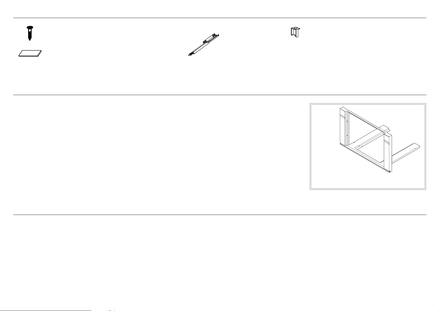
2PARTS SUPPLIED
Screws
Rails (2)
(7)
Spacers
(4) for side
(4) for bottom
3PRIOR TO INSTALLATION
●
The countertop and coffee maker cavity are square and level, and are the required dimensions.
●
The installation will comply with all clearance requirements and applicable standards and regulations.
●
The isolating switch will be easily accessible to the customer with the coffee maker installed.
●
The electrician provides sufficient free length of power supply cable to reach from the bottom rear of the cavity
to at least 1.5m in front of the bottom edge of the opening.
●
The cable may enter the cavity from the side, top or bottom, but top entry must be at the rear of the cavity.
●
The coffee maker connection socket (if fitted) is outside the cavity if the oven is flush to the rear wall.
●
The coffee maker will rest on a surface that can support its weight.
●
The height from the floor suits the customer.
●
You consult local building authorities and by-laws if in doubt regarding installation.
IMPORTANT!
Some environmental factors and cooking habits can cause condensation in and around the coffee maker during use.
To protect surrounding cabinetry from possible damage caused by frequent or excessive condensation, we recommend
moisture-proofing the cavity.
Clip (1)
Optional Trim kit installation
If you are using a 762mm trim kit, refer
to the separate Trim Kit Installation Guide.
4AFTER INSTALLATION
IMPORTANT!
Take extra care not to damage the lower trim of the coffee maker during installation. The trim is important for correct air circulation and allows the door to open and close without obstruction.
The manufacturer does not accept any responsibility for damage resulting from incorrect installation.
●
The coffee maker can be used fully without obstruction.
●
The power supply cable does not touch any hot metal parts.
●
The isolating switch is easily accessible to the customer with the coffee maker installed.
●
You complete the ‘Final checklist’ at the end of the installation.
●
If, after following the instructions given, correct performance cannot be achieved, please contact your nearest Fisher & Paykel Authorised Service Center, Customer Care, or
contact us through our local website listed at the end of this document.
COFFEE MAKER INSTALLATION GUIDE|3
Page 6
E
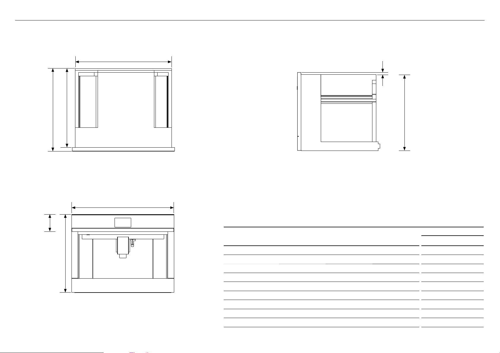
5PRODUCT DIMENSIONS
H
CF
I
A
TOP
B
FRONT
D
SIDE
PRODUCT DIMENSIONS
Overall height of product 458
A
Overall width of product 596
B
Overall depth of product (excluding dials) 480
C
Height of chassis 445
D
Width of chassis 560
E
Depth of chassis 460
F
Depth of coffee maker frame and control panel 20
G
Stepdown control panel to chassis 13
H
Height of control panel 100
I
EB60 MODELS
mm
4|COFFEE MAKER INSTALLATION GUIDE
Page 7
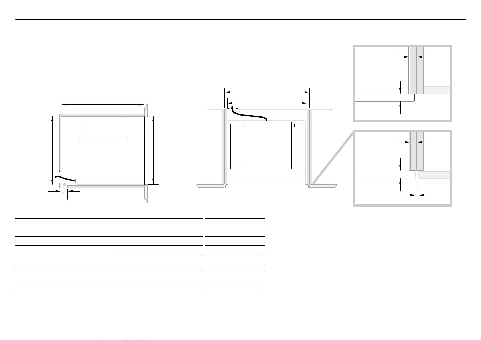
6ACABINETRY DIMENSIONS (460mm HIGH CAVITY)
Verify the minimum measurements required for correct installation of the appliance. The coffee maker must be
installed in a column and the column must be firmly fixed to the wall with commercially available brackets.
IMPORTANT!
●
All installation or maintenance operations must be performed with the appliance disconnected
from the mains electricity supply.
●
Kitchen furniture in direct contact with the appliance must be heat resistant 65°C min.
●
To guarantee correct ventilation, leave a gap at the bottom of the cabinet
(see measurements below).
M
Lk
n
J
I
Electrical supply
TOPSIDE
PROUD INSTALL
16–20mm
20mm
FLUSH INSTALL
16–20mm
20mm
2mm
CABINETRY DIMENSIONS
EB60 MODELS
Minimum inside width of cavity 560
I
Overall width of cabinetry 600
J
Minimum inside height of cavity 450
K
Overall height of cabinetry 460
L
Minimum inside depth of cavity 545
M
Ventilation Air Gap 50
n
mm
COFFEE MAKER INSTALLATION GUIDE|5
Page 8
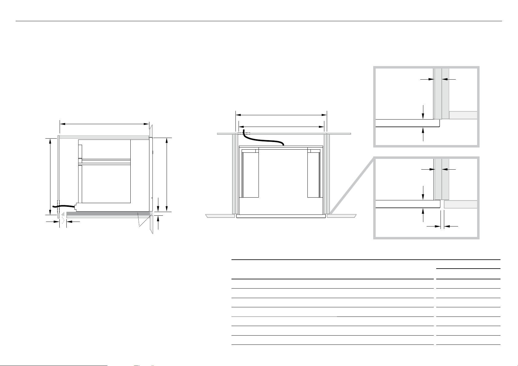
6BCABINETRY DIMENSIONS (480mm CAVITY TRIM KIT)
Verify the minimum measurements required for correct installation of the appliance. The coffee maker must be
installed in a column and the column must be firmly fixed to the wall with commercially available brackets.
IMPORTANT!
●
All installation or maintenance operations must be performed with the appliance disconnected
from the mains electricity supply.
●
Kitchen furniture in direct contact with the appliance must be heat resistant 65°C min.
●
To guarantee correct ventilation, leave a gap at the bottom of the cabinet
(see measurements below).
J
M
I
Electrical supply
PROUD INSTALL
16–20mm
20mm
n
Lower
Trim kit
o
FLUSH INSTALL
16–20mm
Lk
20mm
TOPSIDE
CABINETRY DIMENSIONS
Minimum inside width of cavity 560
I
Overall width of cabinetry 600
J
Minimum inside height of cavity 470
K
Overall height of cabinetry 480
L
Minimum inside depth of cavity 545
M
Ventilation air vent 50
n
Height of trim kit
o
2mm
EB60 MODELS
mm
20
6|COFFEE MAKER INSTALLATION GUIDE
Page 9
2mm
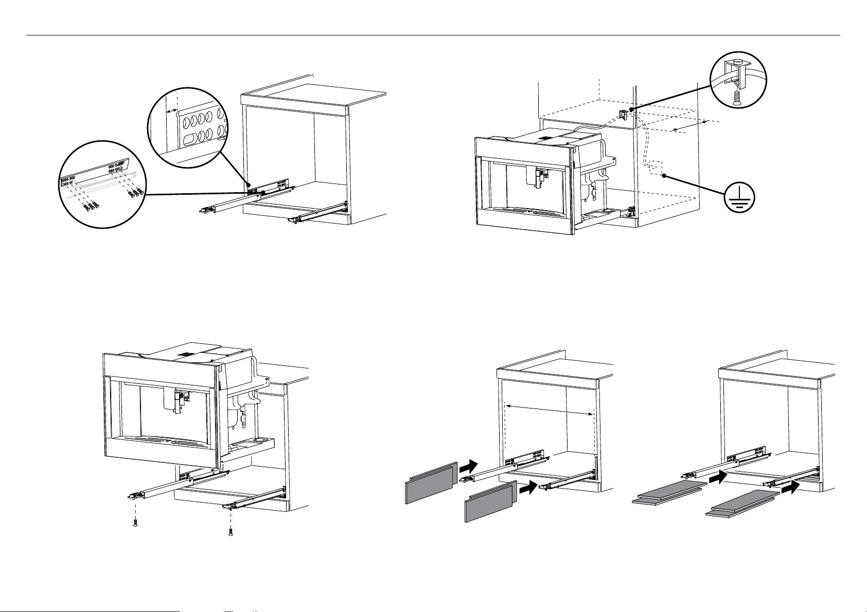
7INSTALLATION INSTRUCTIONS
approx. 350mm
1 Position the rails on the sides of the cabinet. Fix with the screws provided, then extract
them completely.
●
If the coffee maker is installed over a warmer drawer, use the top surface of this as
a reference to position the rails.
●
In this case, there will be no surface to rest the rails on.
●
Position and fix the lock hook with the four screws provided, as shown in the figure.
3 Position the appliance on the rails, making sure the pins are correctly inserted
in the housings, then fix it with the screws supplied. If the height of the appliance
requires adjusting, use the spacer disks provided.
2 Fix the power cable with the clip. The power cable must be long enough to allow
the appliance to be extracted from the cabinet to fill the coffee bean container.
●
The appliance must be earthed in compliance with legislation.
●
Electrical connections must be performed by a qualified electrician following
the instructions.
560mm + 1mm
4 If necessary, correct alignment of the appliance by positioning the spacers
supplied under or at the sides of the support.
COFFEE MAKER INSTALLATION GUIDE|7
Page 10

8FINAL CHECKLIST
TO BE COMPLETED BY THE INSTALLER
F Make sure the coffee maker is level and securely fitted to the cabinetry.
F Check the lower trim is undamaged.
F Check there is adequate clearance. This is to ensure correct air circulation.
F Make sure any cable ties and internal packaging has been removed from the coffee maker cavity.
F Make sure all coffee maker vents and openings are clear and free of any obstruction or damage.
IMPORTANT!
Failure to make sure all vents are clear may result in poor product performance.
F Make sure the isolating switch is accessible by the customer.
TEST OPERATION:
F Turn the power to the coffee maker on. The display should light up.
F Have you demonstrated the basic operation to the customer?
F Fill the water tank to the indicated level.
Complete and keep for safe reference:
Model
Serial No.
Purchase Date
Purchaser
Dealer Address
Installer’s Name
Installer’s Signature
Installation Company
Installation Date
8|COFFEE MAKER INSTALLATION GUIDE
Page 11

STEAM OVEN
OS60 models
Page 12

1SAFETY AND WARNINGS
Installation
WARNING!
Electrical Shock Hazard
Before carrying out any work on the electrical section of the appliance,
it must be disconnected from the mains electricity supply.
Connection to a good earth wiring system is absolutely essential
and mandatory.
Alterations to the domestic wiring system must only be made by a
qualified electrician
Failure to follow this advice may result in electrical shock or death.
WARNING!
Fire Hazard
Do not use adapters, reducers, or branching devices to connect this
appliance to the mains power supply.
Failure to follow this advice may result in overheating, burning, or fire.
WARNING!
Cut Hazard
Take care – some edges are sharp.
Failure to use caution could result in injury or cuts.
IMPORTANT SAFETY INSTRUCTIONS!
To avoid hazard, follow these instructions carefully before installing or using this appliance.
●
Save these instructions for the local inspectors use.
●
Please make this information available to the person installing the appliance – doing
so could reduce your installation costs.
●
This oven is to be installed and connected to the electricity supply only by an
authorised person.
●
If the installation requires alterations to the domestic electrical system, call a qualified
electrician. The electrician should also check that the socket cable section is suitable
for the electricity drawn by the oven.
●
The oven must be earthed.
●
Installation must comply with your local building and electricity regulations.
●
This appliance must be installed and connected to the mains power supply only by a
suitably qualified person according to these installation instructions and in compliance
with any applicable local building and electricity regulations. Failure to install the
appliance correctly could invalidate any warranty or liability claims.
●
If the power supply cable is damaged, it must be replaced by the manufacturer, its
service agent or similarly qualified person in order to avoid a hazard.
●
A circuit breaker is recommended.
●
Do not use adaptors, reducers or branching devices to connect the oven to the mains
electricity supply, as they can cause overheating and burning.
●
Make sure the cavity is completely sealed with no gaps. This is to ensure the oven
cooling system functions correctly.
Electrical requirements
●
Connect oven with copper wire only.
●
Do not cut the conduit.
●
A U.L. listed conduit connector must be provided at the junction box.
●
Do not earth to a gas pipe.
●
Do not have a fuse in the earthed or neutral circuit.
●
Fuse both sides of the line.
●
A time delay fuse or circuit breaker is recommended. If using a time delay fuse, then
fuse both sides of the line.
●
Flexible armored cable from the appliance should be connected directly
to the junction box.
●
Connect directly to the fused disconnect (or circuit breaker box) through flexible,
armored or non-metallic sheathed, copper cable (with earthed wire).
●
If codes permit and a separate earthed wire is used, it is recommended that a
qualified electrician determine that the earthed path and wire gauge are in
accordance with local codes.
IMPORTANT!
SAVE THESE INSTRUCTIONS
The models shown in this installation guide may not be available in all markets and are subject to change at any time. For current details about model and specification availability in your country,
please go to our website fisherpaykel.com or contact your local Fisher & Paykel dealer.
10|STEAM OVEN INSTALLATION GUIDE
Page 13

2PRIOR TO INSTALLATION
●
The countertop and oven cavity are square and level, and are the required dimensions.
●
The installation will comply with all clearance requirements and applicable standards and regulations.
●
The isolating switch will be easily accessible to the customer with the oven installed.
●
The electrician provides sufficient free length of power supply cable to reach from the bottom rear of the cavity
to at least 1.5m in front of the bottom edge of the opening.
●
The cable may enter the cavity from the side, top or bottom, but top entry must be at the rear of the cavity.
●
The oven connection socket (if fitted) is outside the cavity if the oven is flush to the rear wall.
●
The oven will rest on a surface that can support its weight.
●
The height from the floor suits the customer.
●
You consult local building authorities and by-laws if in doubt regarding installation.
IMPORTANT!
Some environmental factors and cooking habits can cause condensation in and around the oven during use.
To protect surrounding cabinetry from possible damage caused by frequent or excessive condensation, we
recommend moisture-proofing the oven cavity.
Optional Trim kit installation
If you are using a 762mm trim kit, refer
to the separate Trim Kit Installation Guide.
3AFTER INSTALLATION
IMPORTANT!
Take extra care not to damage the lower trim of the oven during installation. The trim is important for correct air circulation and allows the door to open and close without obstruction.
The manufacturer does not accept any responsibility for damage resulting from incorrect installation.
●
The oven door(s) can open fully without obstruction.
●
The power supply cable does not touch any hot metal parts.
●
The isolating switch is easily accessible to the customer with the oven installed.
●
You complete the ‘Final checklist’ at the end of the installation.
●
If, after following the instructions given, correct performance cannot be achieved, please contact your nearest Fisher & Paykel Authorised Service Center, Customer Care, or
contact us through our local website listed at the end of this document.
STEAM OVEN INSTALLATION GUIDE|11
Page 14

CF
4PRODUCT DIMENSIONS
E
D
G
A
TOP SIDE
B
PRODUCT DIMENSIONS
Overall height of product 458
A
Overall width of product 596
B
Overall depth of product (excluding handle and dials) 562
C
Height of chassis 445
D
Width of chassis 556
E
Depth of chassis 540
F
Depth of oven frame and control panel
G
FRONT
(=distance between front of chassis and front of oven door, excl. knobs)
Depth of oven door when fully open
H
(measured from front of control panel)
H
OS60 MODELS
mm
22
320
12|STEAM OVEN INSTALLATION GUIDE
Page 15

5ACABINETRY DIMENSIONS (460mm HIGH CAVITY)
●
The oven can be installed under a cooktop, in a column.
●
The cabinet material must be able to withstand heat.
●
The oven must be centered within the walls of the cabinet and fixed with the screws and bushings that are provided.
PROUD INSTALL
16–20mm
M
Electrical supply
Lk
n
CABINETRY DIMENSIONS
Minimum inside width of cavity 560
I
Overall width of cabinetry 600
J
Minimum inside height of cavity 450
K
Overall height of cabinetry 460
L
Minimum inside depth of cavity 560
M
Ventilation air vent
n
OS60 MODELS
mm
50
J
22mm
I
FLUSH INSTALL
22mm
TOPSIDE
2mm
16–20mm
Note: if installing a cooktop above the oven, ensure adequate clearance is provided for the cooktop as per the cooktop
manufacturer’s instructions.
STEAM OVEN INSTALLATION GUIDE|13
Page 16

5BCABINETRY DIMENSIONS (480mm CAVITY TRIM KIT)
●
The oven must be installed under a cook top, in a column.
●
The cabinet material must be able to withstand heat.
●
The oven must be centered within the walls of the cabinet and fixed with the screws and bushings that are provided.
To install the trim kit, refer to the instructions which accompany it.
PROUD INSTALL
16–20mm
n
M
Lower
Trim kit
o
J
22mm
I
Electrical supply
FLUSH INSTALL
16–20mm
Lk
22mm
TOPSIDE
CABINETRY DIMENSIONS
Minimum inside width of cavity 560
I
Overall width of cabinetry 600
J
Minimum inside height of cavity 465
K
Overall height of cabinetry 480
L
Minimum inside depth of cavity 560
M
Ventilation air vent 50
n
Height of trim kit
o
2mm
OS60 MODELS
mm
20
14|STEAM OVEN INSTALLATION GUIDE
Note: if installing a cooktop above the oven, ensure adequate clearance is provided for the cooktop as per the cooktop
manufacturer’s instructions.
Page 17

6ELECTRICAL HOOK-UP
Before connecting to the electricity, make sure that the:
●
specifications of the electrical system match with what is detailed on the serial number plate applied to the front of the oven.
●
system has an effective earth connection compliant with current standards and laws.
The earth connection is required by law. The cable must not, at any point, reach a temperature greater than 50°C above room temperature.
This oven must be connected to the electricity through a power supply cable and plug that is compatible with the outlet
of the electrical system that powers this oven. If a fixed appliance does not have a power cord and plug, or another device
that ensures disconnection from the mains, with an opening distance of the contacts that allows complete disconnection,
such disconnection devices must be provided in the power supply mains conforming to the installation rules.
The omnipolar socket or switch must be easy to reach when the appliance is installed.
Note: the manufacturer declines all liability if the usual accident prevention standards and the above instructions are not followed.
7SECURE THE OVEN TO THE CABINETRY
1 Position the oven in the prepared cavity.
IMPORTANT!
Do not lift the oven by the door handle.
2 Use the supplied screws and spacers to secure the oven
to the cabinetry.
Ensure supplied spacer
is fitted between oven
and cabinetry
IMPORTANT!
●
Do not over-tighten the screws.
●
Take care not to damage the lower trim of the oven.
●
Do not seal the oven into the cabinetry with silicone or glue.
This makes future servicing difficult. Fisher & Paykel will not cover
the costs of removing the oven, or of damage caused by this removal.
STEAM OVEN INSTALLATION GUIDE|15
Page 18

8FINAL CHECKLIST
TO BE COMPLETED BY THE INSTALLER
F Make sure the oven is level and securely fitted to the cabinetry.
F Check the lower trim is undamaged.
F Open the (lower) oven door slowly until it is fully open and check there is adequate clearance between the bottom of the door and the lower trim.
This is to ensure correct air circulation. Should the lower trim become damaged, straighten the trim and ensure the oven door opens fully without obstruction.
F Make sure any cable ties and internal packaging has been removed from the oven cavity.
F Make sure all oven vents and openings are clear and free of any obstruction or damage.
IMPORTANT!
Failure to make sure all oven vents are clear may result in poor product performance.
F Make sure the isolating switch is accessible by the customer.
TEST OPERATION:
F Have you demonstrated the basic operation to the customer?
Refer to User Guide.
Complete and keep for safe reference:
Model
Serial No.
Purchase Date
Purchaser
Dealer Address
Installer’s Name
Installer’s Signature
Installation Company
Installation Date
16|STEAM OVEN INSTALLATION GUIDE
Page 19

MICROWAVE OVEN
OM60 models
Page 20

1SAFETY AND WARNINGS
Installation
WARNING!
Electrical Shock Hazard
Before carrying out any work on the electrical section of the appliance,
it must be disconnected from the mains electricity supply.
Connection to a good earth wiring system is absolutely essential
and mandatory.
Alterations to the domestic wiring system must only be made by a
qualified electrician
Failure to follow this advice may result in electrical shock or death.
WARNING!
Fire Hazard
Do not use adapters, reducers, or branching devices to connect this
appliance to the mains power supply.
Failure to follow this advice may result in overheating, burning, or fire.
WARNING!
Cut Hazard
Take care – some edges are sharp.
Failure to use caution could result in injury or cuts.
IMPORTANT!
The oven’s identification plate is accessible
when the appliance is installed.
This identification plate, which is visible
when you open the door, shows all the
information you will need when requesting
replacement parts for the appliance.
IMPORTANT SAFETY INSTRUCTIONS!
To avoid hazard, follow these instructions carefully before installing or using this appliance.
●
Save these instructions for the local inspectors use.
●
Please make this information available to the person installing the appliance – doing
so could reduce your installation costs.
●
This oven is to be installed and connected to the electricity supply only by an
authorised person.
●
If the installation requires alterations to the domestic electrical system, call a qualified
electrician. The electrician should also check that the socket cable section is suitable
for the electricity drawn by the oven.
●
The oven must be earthed.
●
Installation must comply with your local building and electricity regulations.
●
This appliance must be installed and connected to the mains power supply only by a
suitably qualified person according to these installation instructions and in compliance
with any applicable local building and electricity regulations. Failure to install the
appliance correctly could invalidate any warranty or liability claims.
●
If the power supply cable is damaged, it must be replaced by the manufacturer, its
service agent or similarly qualified person in order to avoid a hazard.
●
A circuit breaker is recommended.
●
Do not use adaptors, reducers or branching devices to connect the oven to the mains
electricity supply, as they can cause overheating and burning.
●
Make sure the cavity is completely sealed with no gaps. This is to ensure the oven
cooling system functions correctly.
Electrical requirements
●
Connect oven with copper wire only.
●
Do not cut the conduit.
●
A U.L. listed conduit connector must be provided at the junction box.
●
Do not earth to a gas pipe.
●
Do not have a fuse in the earthed or neutral circuit.
●
Fuse both sides of the line.
●
A time delay fuse or circuit breaker is recommended. If using a time delay fuse, then
fuse both sides of the line.
●
Flexible armored cable from the appliance should be connected directly
to the junction box.
●
Connect directly to the fused disconnect (or circuit breaker box) through flexible,
armored or non-metallic sheathed, copper cable (with earthed wire).
●
If codes permit and a separate earthed wire is used, it is recommended that a
qualified electrician determine that the earthed path and wire gauge are in
accordance with local codes.
IMPORTANT!
SAVE THESE INSTRUCTIONS
The models shown in this installation guide may not be available in all markets and are subject to change at any time. For current details about model and specification availability in your country,
please go to our website fisherpaykel.com or contact your local Fisher & Paykel dealer.
18|MICROWAVE OVEN INSTALLATION GUIDE
Page 21

2PRIOR TO INSTALLATION
●
The countertop and oven cavity are square and level, and are the required dimensions.
●
The installation will comply with all clearance requirements and applicable standards and regulations.
●
The isolating switch will be easily accessible to the customer with the oven installed.
●
The electrician provides sufficient free length of power supply cable to reach from the bottom rear of the cavity
to at least 1.5m in front of the bottom edge of the opening.
●
The cable may enter the cavity from the side, top or bottom, but top entry must be at the rear of the cavity.
●
The oven connection socket (if fitted) is outside the cavity if the oven is flush to the rear wall.
●
The oven will rest on a surface that can support its weight.
●
The height from the floor suits the customer.
●
You consult local building authorities and by-laws if in doubt regarding installation.
IMPORTANT!
Some environmental factors and cooking habits can cause condensation in and around the oven during use.
To protect surrounding cabinetry from possible damage caused by frequent or excessive condensation, we
recommend moisture-proofing the oven cavity.
Optional Trim kit installation
If you are using a 762mm trim kit, refer
to the separate Trim Kit Installation Guide.
3AFTER INSTALLATION
IMPORTANT!
Take extra care not to damage the lower trim of the oven during installation. The trim is important for correct air circulation and allows the door to open and close without obstruction.
The manufacturer does not accept any responsibility for damage resulting from incorrect installation.
●
The oven door(s) can open fully without obstruction.
●
The power supply cable does not touch any hot metal parts.
●
The isolating switch is easily accessible to the customer with the oven installed.
●
You complete the ‘Final checklist’ at the end of the installation.
●
If, after following the instructions given, correct performance cannot be achieved, please contact your nearest Fisher & Paykel Authorised Service Center, Customer Care, or
contact us through our local website listed at the end of this document.
MICROWAVE OVEN INSTALLATION GUIDE|19
Page 22

CF
4PRODUCT DIMENSIONS
E
D
G
A
TOP SIDE
B
PRODUCT DIMENSIONS
Overall height of product 458
A
Overall width of product 596
B
Overall depth of product (excluding handle and dials) 562
C
Height of chassis 445
D
Width of chassis 556
E
Depth of chassis 540
F
Depth of oven frame and control panel
G
FRONT
(=distance between front of chassis and front of oven door, excl. knobs)
Depth of oven door when fully open
H
(measured from front of control panel)
H
OM60 MODELS
mm
22
320
20|MICROWAVE OVEN INSTALLATION GUIDE
Page 23

5ACABINETRY DIMENSIONS (460mm HIGH CAVITY)
●
The oven can be installed under a cooktop, in a column
●
The cabinet material must be able to withstand heat.
●
The oven must be centered within the walls of the cabinet and fixed with the screws and bushings that are provided.
PROUD INSTALL
16–20mm
M
Electrical supply
Lk
n
CABINETRY DIMENSIONS
Minimum inside width of cavity 560
I
Overall width of cabinetry 600
J
Minimum inside height of cavity 450
K
Overall height of cabinetry 460
L
Minimum inside depth of cavity 560
M
Ventilation air vent
n
OM60 MODELS
mm
50
J
22mm
I
FLUSH INSTALL
22mm
TOPSIDE
2mm
16–20mm
Note: if installing a cooktop above the oven, ensure adequate clearance is provided for the cooktop as per the cooktop
manufacturer’s instructions.
MICROWAVE OVEN INSTALLATION GUIDE|21
Page 24

5BCABINETRY DIMENSIONS (480mm CAVITY TRIM KIT)
●
The oven must be installed under a cook top, in a column.
●
The cabinet material must be able to withstand heat.
●
The oven must be centered within the walls of the cabinet and fixed with the screws and bushings that are provided.
To install the trim kit, refer to the instructions which accompany it.
PROUD INSTALL
16–20mm
n
M
Lower
Trim kit
o
J
22mm
I
Electrical supply
FLUSH INSTALL
16–20mm
Lk
22mm
TOPSIDE
CABINETRY DIMENSIONS
Minimum inside width of cavity 560
I
Overall width of cabinetry 600
J
Minimum inside height of cavity 465
K
Overall height of cabinetry 480
L
Minimum inside depth of cavity 560
M
Ventilation air vent 50
n
Height of trim kit
o
2mm
OM60 MODELS
mm
20
22|MICROWAVE OVEN INSTALLATION GUIDE
Note: If installing a cooktop above the oven, ensure adequate clearance is provided for the cooktop as per the cooktop
manufacturer’s instructions.
Page 25

6ELECTRICAL HOOK-UP
Before connecting to the electricity, make sure that the:
●
specifications of the electrical system match with what is detailed on the serial number plate applied to the front of the oven.
●
system has an effective earth connection compliant with current standards and laws.
The earth connection is required by law. The cable must not, at any point, reach a temperature greater than 50°C above room temperature.
This oven must be connected to the electricity through a power supply cable and plug that is compatible with the outlet
of the electrical system that powers this oven. If a fixed appliance does not have a power cord and plug, or another device
that ensures disconnection from the mains, with an opening distance of the contacts that allows complete disconnection,
such disconnection devices must be provided in the power supply mains conforming to the installation rules.
The omnipolar socket or switch must be easy to reach when the appliance is installed.
Note: the manufacturer declines all liability if the usual accident prevention standards and the above instructions are not followed.
7SECURE THE OVEN TO THE CABINETRY
1 Position the oven in the prepared cavity.
IMPORTANT!
Do not lift the oven by the door handle.
2 Use the supplied screws and spacers to secure the oven
to the cabinetry.
Ensure supplied spacer
is fitted between oven
and cabinetry
IMPORTANT!
●
Do not over-tighten the screws.
●
Take care not to damage the lower trim of the oven.
●
Do not seal the oven into the cabinetry with silicone or glue.
This makes future servicing difficult. Fisher & Paykel will not cover
the costs of removing the oven, or of damage caused by this removal.
MICROWAVE OVEN INSTALLATION GUIDE|23
Page 26

8FINAL CHECKLIST
TO BE COMPLETED BY THE INSTALLER
F Make sure the oven is level and securely fitted to the cabinetry.
F Check the lower trim is undamaged.
F Open the oven door (lower) slowly until it is fully open and check there is adequate clearance between the bottom of the door and the lower trim.
This is to ensure correct air circulation. Should the lower trim become damaged, straighten the trim and ensure the oven door opens fully without obstruction.
F Make sure any cable ties and internal packaging has been removed from the oven cavity.
F Make sure all oven vents and openings are clear and free of any obstruction or damage.
IMPORTANT!
Failure to make sure all oven vents are clear may result in poor product performance.
F Make sure the isolating switch is accessible by the customer.
TEST OPERATION:
F Have you demonstrated the basic operation to the customer?
Refer to User Guide.
Complete and keep for safe reference:
Model
Serial No.
Purchase Date
Purchaser
Dealer Address
Installer’s Name
Installer’s Signature
Installation Company
Installation Date
24|MICROWAVE OVEN INSTALLATION GUIDE
Page 27

Page 28

FISHERPAYKEL.COM
© Fisher & Paykel Appliances 2018. All rights reserved.
The product specifications in this booklet apply to the specific products
and models described at the date of issue. Under our policy of continuous
product improvement, these specifications may change at any time. You
should therefore check with your Dealer to ensure this booklet correctly
describes the product currently available.
NZ AU GB IE
591587A 02.18
 Loading...