

Fisher & Paykel myAIRVO 2 User Manual
TM
User Manual
myAIRVO
2


SECTION
English ......................................................................... A
Deutsch ....................................................................... B
Español ........................................................................ C
Français ....................................................................... D
Italiano ......................................................................... E
Nederlands ................................................................. F
Português ................................................................... G
Dansk ............................................................................ H
Suomi ........................................................................... I
Norsk ............................................................................ J
Svenska ........................................................................ K

BEFORE YOU START
• This User Manual is intended for patients.
• This User Manual applies to myAIRVO 2 units with LOT numbers 130621 and above.
• Read this User Manual including all warnings. Failure to do so may result in injury. In addition, watch the
myAIRVO 2 Video Guide. Keep them both in a safe place for future reference.
• Before the myAIRVO 2 is used for the first time, it must be set up according to the instructions in the
myAIRVO 2 Technical Manual. This should be carried out by a healthcare professional or medical technician.
• If the unit is ever used by multiple patients, the unit must be cleaned and disinfected between patients
according to instructions in the Disinfection Kit Manual.
• For further assistance, please contact your Fisher & Paykel Healthcare representative.
TABLE OF CONTENTS
1. Overview ...................................................................................................................................................... A - 2
Intended Use ................................................................................................................................................................................ A - 2
Warnings ........................................................................................................................................................................................ A - 2
myAIRVO 2 and Accessories ................................................................................................................................................. A - 3
2. Setting up myAIRVO 2 ........................................................................................................................... A - 4
3. Using myAIRVO 2 ..................................................................................................................................... A - 7
Advanced settings ..................................................................................................................................................................... A - 8
Oxygen ........................................................................................................................................................................................... A - 10
Alarms ............................................................................................................................................................................................. A - 11
English
4. Cleaning and maintenance ................................................................................................................... A - 13
Daily cleaning instructions ...................................................................................................................................................... A - 13
Weekly cleaning instructions ................................................................................................................................................. A - 13
Schedule for changing accessories ..................................................................................................................................... A - 14
Filter replacement ...................................................................................................................................................................... A - 14
Servicing ........................................................................................................................................................................................ A - 14
5. Technical Information ............................................................................................................................. A - 15
A – 1

1. OVERVIEW
The myAIRVO 2 is a humidifier with integrated flow generator that delivers warmed and humidified respiratory
gases to spontaneously breathing patients through a variety of patient interfaces.
INTENDED USE
The myAIRVO 2 is for the treatment of spontaneously breathing patients who would benefit from receiving
high flow warmed and humidified respiratory gases. This includes patients who have had upper airways
bypassed. The flow may be from 2 - 60L/min depending on the patient interface. The myAIRVO 2 is for
patients in homes and long-term care facilities.
USA Federal Law restricts this unit for sale by or on the order of a physician.
WARNINGS
!
• Nasal delivery of respiratory gases generates flow-dependent positive airway pressure (PAP). This must
be taken into account where PAP could have adverse eects on a patient.
• The unit is not intended for life support.
To avoid burns:
• The unit should only be used with interfaces, water chambers and breathing tubes specified in this user
manual.
• Using the breathing tube or interface for longer than the specified time can result in serious injury
including infection.
• Before using oxygen with the unit, read all warnings in the “Oxygen” section of this manual.
• Never operate the unit if:
• the heated breathing tube has been damaged with holes, tears or kinks,
• it is not working properly,
• the case screws have ever been loosened.
• Do not block the flow of the air through the unit and breathing tube.
• The unit should be located in a position where ventilation around the unit is not restricted.
• Never block the air openings of the unit or place it on a soft surface such as a bed or couch/sofa, where
the filter area may be blocked. Keep the air openings free of lint, hair etc.
To avoid electric shock:
• Do not store or use the unit where it can fall or be pulled into water. If water has entered the unit enclosure,
disconnect the power cord and discontinue use.
• Never operate the unit if:
• it has been dropped or damaged,
• it has a damaged power cord or plug,
• it has been dropped into water.
• Avoid unnecessary removal of the power cord from the rear of the device. If removal is necessary, hold the
connector during removal. Avoid pulling on the power cord.
• Return the unit to an authorized service center for examination and repair, except as outlined in this
manual.
To avoid choking, or inhalation of a foreign object:
• Ensure an air filter is fitted when operating your unit.
• Never drop or insert any object into any opening or tube.
Miscellaneous:
• Do not use the unit when the room temperature exceeds 30°C (86°F) or is below 10°C (50°F) as the unit
may switch o. Humidity output will be compromised below 18°C (64°F) and above 28°C (82°F).
• The unit is not suitable for use in the presence of a flammable, anesthetic mixture with air or oxygen or
nitrous oxide.
A – 2
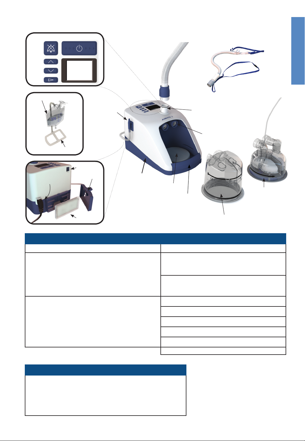
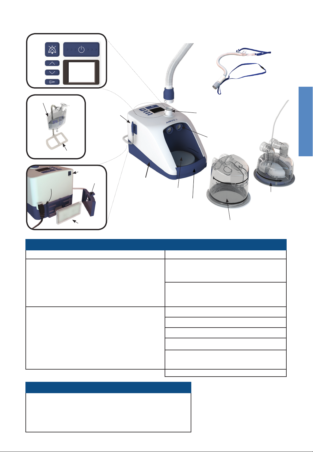
myAIRVO 2 AND ACCESSORIES
ON/OFF (STANDBY)
AUDIO PAUSE
UP
DOWN
MODE
Patient
interface
WATER BAG
COMPACT STAND
POWER CORD
and
CONNECTOR
DISPLAY
SERIAL PORT
FILTER COVER
AIR FILTER
OXYGEN
INLET PORT
myAIRVO 2
(PT100EW)
Heated
breathing
tube
HEATER
PLATE
FINGER
GUARD
HEATED BREATHING TUBE
CONNECTION PORT
CHAMBER PORTS
REUSABLE WATER
CHAMBER (HC360)
AUTO-FILL WATER
CHAMBER (MR290)
(with adapter fitted)
Water chamber
English
Tube & chamber kits and patient interfaces
Tube & chamber kits Interfaces
900PT531
900PT530E Heated breathing tube (1-Pack)
900PT290E
HC360 Reusable water chamber
900PT500 Heated breathing tube (10-Pack)
900PT500E Heated breathing tube (1-Pack)
900PT501
900PT290E
HC360 Reusable water chamber
Heated breathing tube, MR290 auto-fill
chamber and adapter
(10-Pack)
MR290 auto-fill chamber and adapter
(1-Pack)
Heated breathing tube, MR290 auto-fill
chamber and adapter (10-Pack)
MR290 auto-fill chamber and adapter
(1-Pack)
à
à
Miscellaneous
900PT400 Compact stand (for myAIRVO 2 and water bag)
900PT401 Water bag (2-pack)
900PT422 Oxygen inlet extension kit
900PT912 Filter holder
900PT913 Air filter (2-Pack)
OPT012 Wigglepads (OPT316/OPT318) (20-pack)
OPT014 Oxygen Tubing (Optiflow Junior)
A – 3
OPT316 Nasal Cannula - Infant (20-pack)
OPT318 Nasal Cannula - Pediatric (20-pack)
OPT842 Nasal Cannula - Small (20-pack)
OPT844 Nasal Cannula - Medium (20-pack)
OPT846 Nasal Cannula - Large (20-pack)
OPT870 Tracheostomy Direct Connection (20-pack)
RT013 Mask Interface Adapter (20-pack)
-E (1-pack) eg. OPT870E
2. SETTING UP myAIRVO 2
H2O
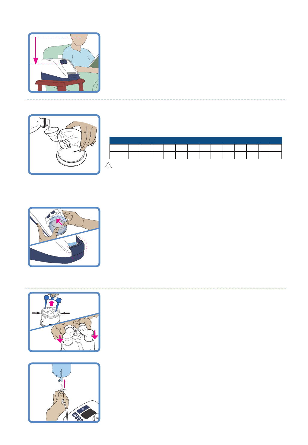
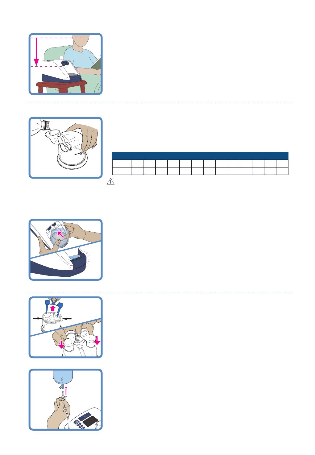
1. BEFORE YOU BEGIN
Place the unit on a low shelf or near the floor beside your bed. It must be
placed below head height and flat.
2. INSTALL WATER CHAMBER
IF USING A HC360 REUSABLE WATER CHAMBER:
With the aid of the supplied funnel, fill the chamber with enough distilled
water for the period of use, but never above the 560 mL fill line.
L/min
WARNINGS
To avoid burns:
• Do not fill the water chamber with hot water.
To avoid electric shock:
• Always remove the water chamber to fill it and always fill with enough distilled
water to prevent it running out.
2 5 10 15 20 25 30 35 40 45 50 55 60
106 42 21 14 11 8 7 6 5 5 4 4 4
hrs
HC360: Flow setting vs usage time
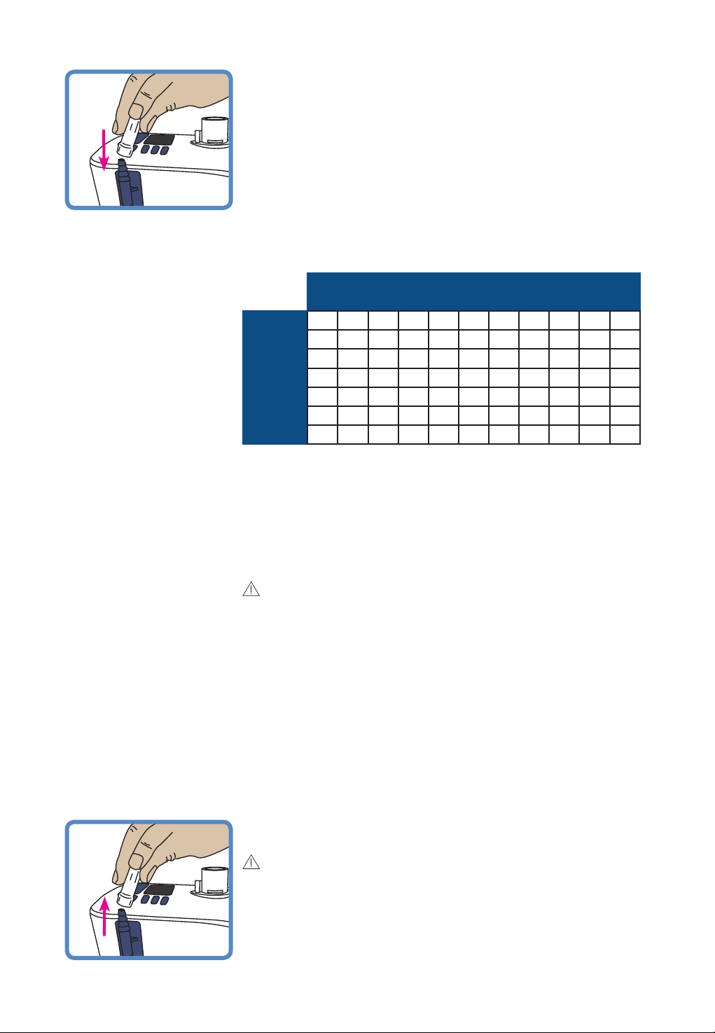
Fit the water chamber to the unit by pressing down the finger guard and
sliding the chamber on, carefully aligning with the blue chamber port ends.
Push the chamber on firmly until the finger guard clicks into place.
Go to Step 3, “Install Heated Breathing Tube”, below.
IF USING THE MR290 AUTO-FILL WATER CHAMBER:
Remove the blue port caps from the chamber by pulling the tear tab
upwards then remove the bracket holding the water supply tube. Fit the
supplied adapter over the two vertical ports on the chamber and push on
fully then clip the water supply tube into position.
Fit the MR290 chamber as described above for the HC360 chamber.
Attach the water bag to the hanging bracket at least 20cm (8”) above
the unit, and push the bag spike into the fitting at the bottom of the bag.
Open the vent cap on the side of the bag spike. The chamber will now
automatically fill to the required level and maintain that level until the
water bag is empty. Use only distilled water and always ensure sucient
water is in the water bag to prevent it from running out.
A – 4
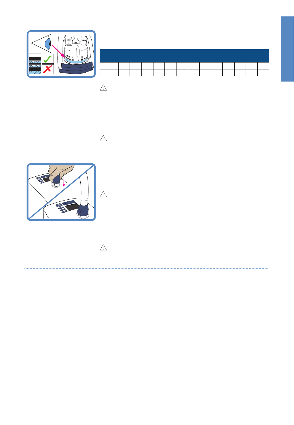
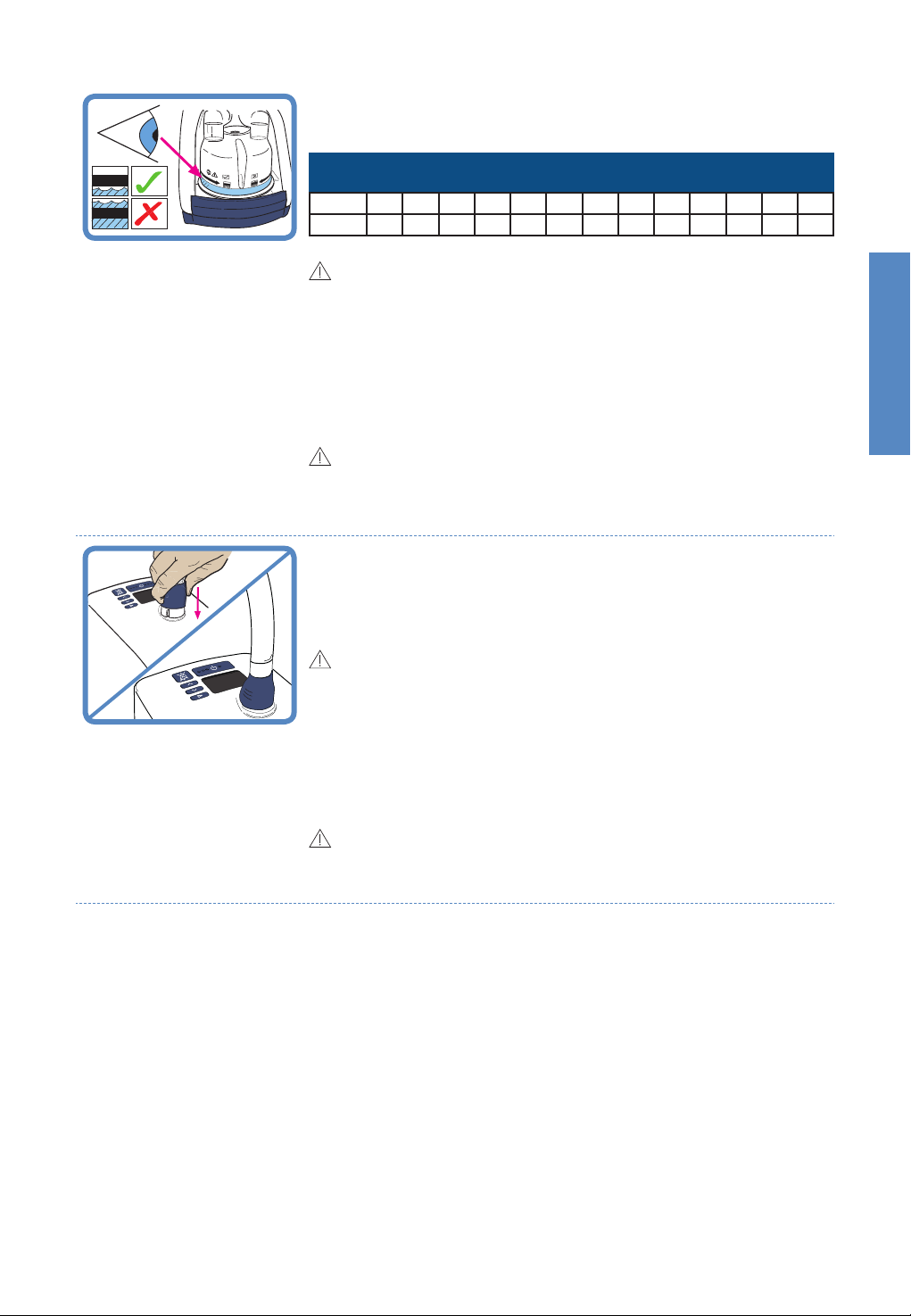
Check that water flows into the chamber and is maintained below the
fill line. If the water level rises above the fill line, replace the chamber
immediately.
MR290: Flow setting vs usage time
(Water bag 900PT401, 1000 mL)
L/min
2 5 10 15 20 25 30 35 40 45 50 55 60
189 76 38 25 19 15 13 11 9 8 8 7 6
hrs
WARNINGS
To avoid burns:
• Do not start the unit without the water chamber in place.
• Do not touch the heater plate, water chamber or chamber base during use.
• The water in the chamber becomes hot during use. Exercise caution when
removing and emptying the chamber.
To avoid electric shock:
• When handling the unit with the water chamber in place, avoid tilting the
machine to prevent any chance of water entering the unit enclosure.
• Empty all the water from the water chamber before transporting the unit.
CAUTIONS
To ensure optimal therapy (MR290 only):
• Do not use the auto-fill MR290 chamber if it has been dropped, or been run dry
and the “water out” alarm has been activated.
3. INSTALL HEATED BREATHING TUBE
One end of the heated breathing tube has a blue plastic sleeve. Lift the
sleeve and slide the connector onto the unit. Push the sleeve down to
lock.
WARNINGS
To avoid burns:
• Do not modify the breathing tube or interface in any way.
• Do not allow the breathing tube to remain in direct contact with skin for
prolonged periods of time.
• Adding heat, above ambient levels, to any part of the breathing tube or interface
e.g. covering with a blanket, or heating it in an incubator or overhead heater for a
neonate, could result in serious injury.
• Do not use an insulating sleeve or any similar accessories which are not
recommended by Fisher & Paykel Healthcare.
CAUTIONS
• Position the heated breathing tube away from any electrical monitoring leads
(EEG, ECG/EKG, EMG, etc), to minimize any possible interference with the
monitored signal.
English
A – 5
4. SELECT PATIENT INTERFACE
The myAIRVO 2 can be used with a variety of patient interfaces. Read the separate user instructions for
the patient interface that will be used, including all warnings.
WARNINGS
To avoid burns:
• Do not modify the breathing tube or interface in any way.
• Do not use any patient interfaces not listed here.
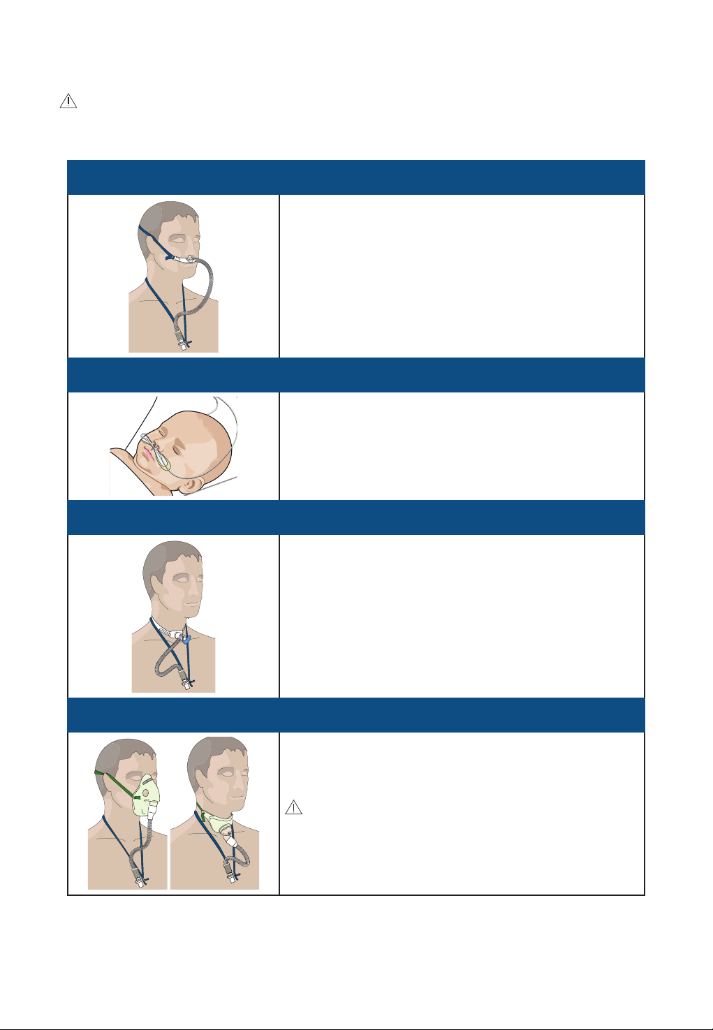
Nasal Cannula
(OPT842/OPT844/OPT846)
If using the nasal interface, place the lanyard around the neck.
Hold the nasal interface in the nose and then place the elastic
loop behind the head, above the ears. The elastic loop can be
adjusted by pulling it at the sides.
Nasal Cannula
(OPT316/OPT318)
Refer to separate user instructions.
Tracheostomy Interface
(OPT870)
If using the tracheostomy interface, place the lanyard around
the neck, attach the tracheostomy tube connector as shown,
and adjust the length of the strap for maximum comfort.
Mask Interface Adapter
(RT013)
If using a standard vented tracheostomy or face mask, connect
the mask’s 22 mm connector to the RT013 Mask Interface
Adapter. Place the lanyard around the neck and fit the mask in
the usual manner.
WARNINGS
• Note that the RT013 Mask Interface Adapter is designed to be used
with vented masks only. Do not use sealed masks.
A – 6
3. USING myAIRVO 2
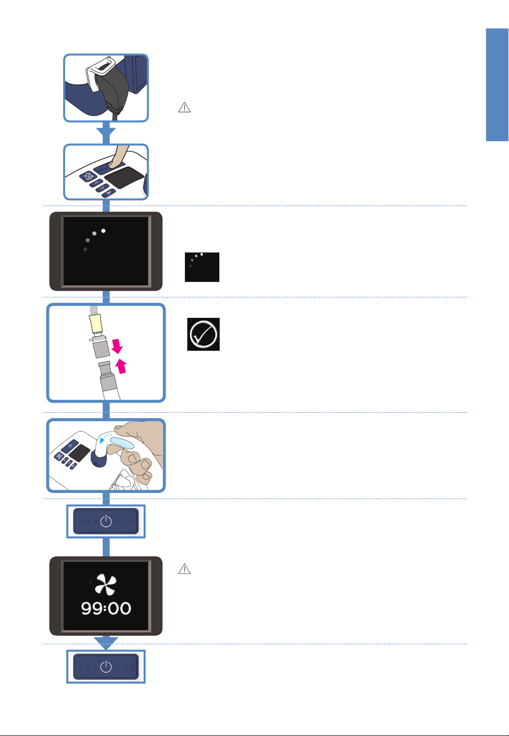
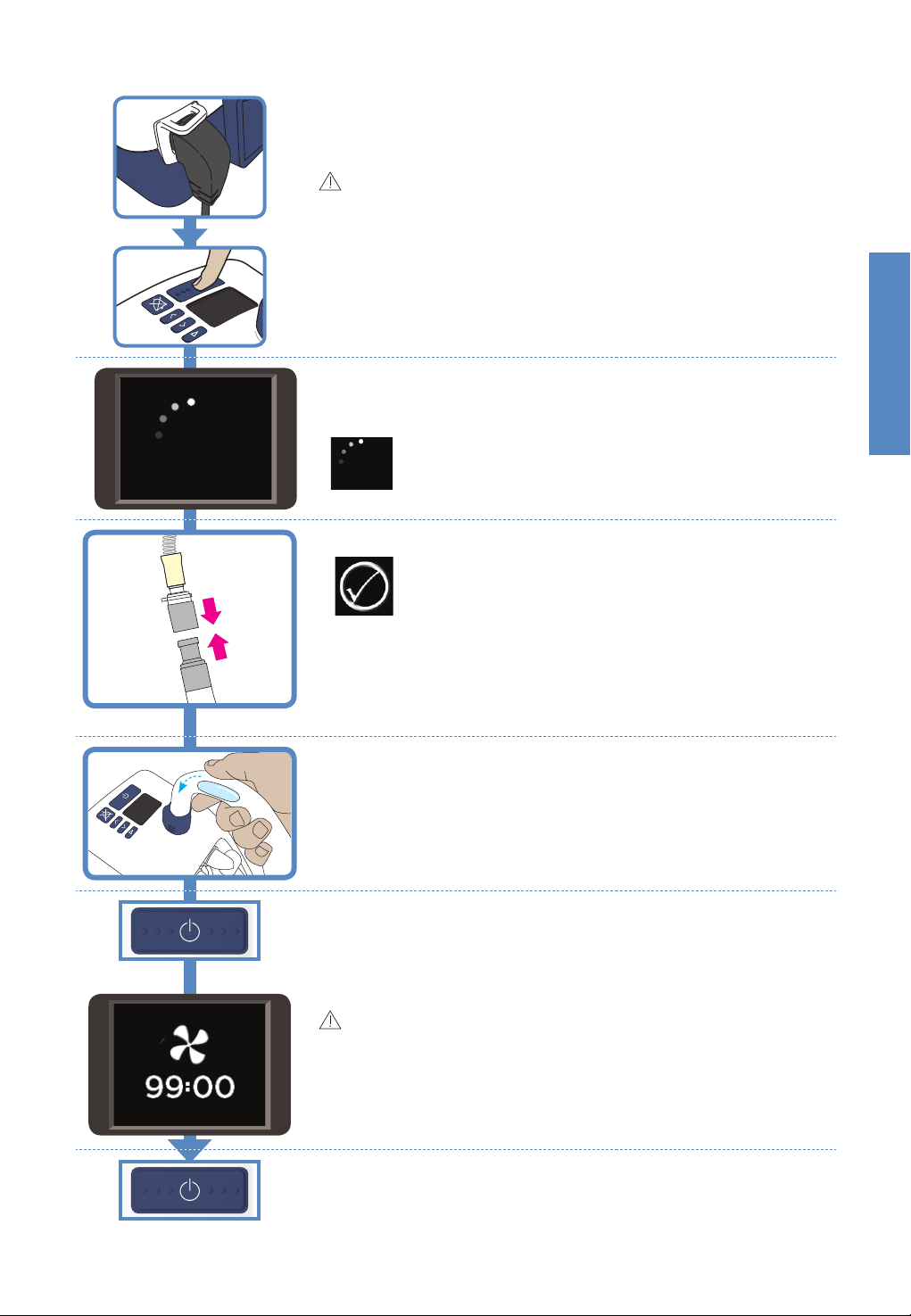
1. SWITCH ON UNIT
Plug the unit’s power cord into the mains power supply. The connector
at the other end of the power cord should be well secured to the rear of
the unit.
WARNINGS
To avoid electric shock:
• Ensure that the unit is dry before plugging into the power socket.
Switch on the unit by pressing the On/O button.
2. WARM-UP
The unit will begin to warm up. You will see a warm-up symbol on the
screen.
3. CONNECT THE PATIENT INTERFACE
English
“Warm-up” symbol
“Ready for use” symbol
When the “Ready for Use” symbol appears on the display, connect the
patient interface to the heated breathing tube. Tighten the lanyard to
take the weight of the heated breathing tube.
When you first use the unit, the air will feel warm. Continue to breathe
normally.
4. AFTER USE
When you have finished using the unit, remove your interface and drain
any excess condensate in the breathing tube by lifting the patient end
of the tube, and allowing the condensate to run into the water chamber.
5. DRYING MODE
Then press and hold the On/O button for 3 seconds until a melody
sounds. The unit will automatically enter Drying Mode and dry the tube
so it is ready for you to use next time. Drying Mode runs for 99 minutes.
The unit will automatically turn o when it is finished.
WARNINGS
To avoid burns:
• Do not wear the interface during Drying Mode. The air is hot and dry and may
cause injury.
• Do not remove the water chamber until drying mode has been completed.
To switch the unit o without completing Drying Mode (this is not
recommended), hold down the On/O button for 5 seconds.
If you unplug the unit’s power cord from the mains power supply while
the unit is still running, the “Power Out” alarm will sound. Press the
“Audio Pause” button to silence this alarm.
A – 7
ADVANCED SETTINGS
When you see the “Warm-up” or “Ready for use” symbols, you can
press the Mode button to view and change advanced settings.
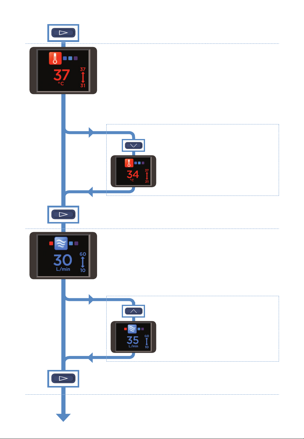
TARGET DEW-POINT TEMPERATURE
You can set the myAIRVO 2 to three target dew-point temperature
settings:
• 37°C (98.6°F)
• 34°C (93°F) [if compliance at 37°C is a problem]
• 31°C (88°F) [for face masks only].
You may not have access to all settings, if:
• the unit is in Junior Mode (limited to 34 °C),
• the unit was initially set up with tighter limits.
The myAIRVO 2 will remember its target dew-point temperature setting
when you switch it o.
To change the target dew-point temperature
setting:
Press the Up and Down buttons to choose the new
setting.
The large number in the center of the screen shows
your chosen setting.
The small numbers near the arrow show the minimum
and maximum accessible settings.
Press the Mode button to move on to the next screen.
TARGET FLOW
You can set the myAIRVO 2 to flows between 10 L/min and 60 L/min, in
increments of 1 L/min (10-25 L/min) and 5 L/min (25-60 L/min).
You may not have access to all settings, if:
• the unit is in Junior Mode (limited to 2 - 25 L/min, in increments of
1 L/min)
• the unit was initially set up with tighter limits.
The myAIRVO 2 will remember its target flow setting when you switch
it o.
To change the target flow setting:
Press the Up and Down buttons to choose the new
setting.
The large number in the center of the screen shows
your chosen setting.
The small numbers near the arrow show the minimum
and maximum accessible settings.
Press the Mode button to move on to the next screen.
A – 8
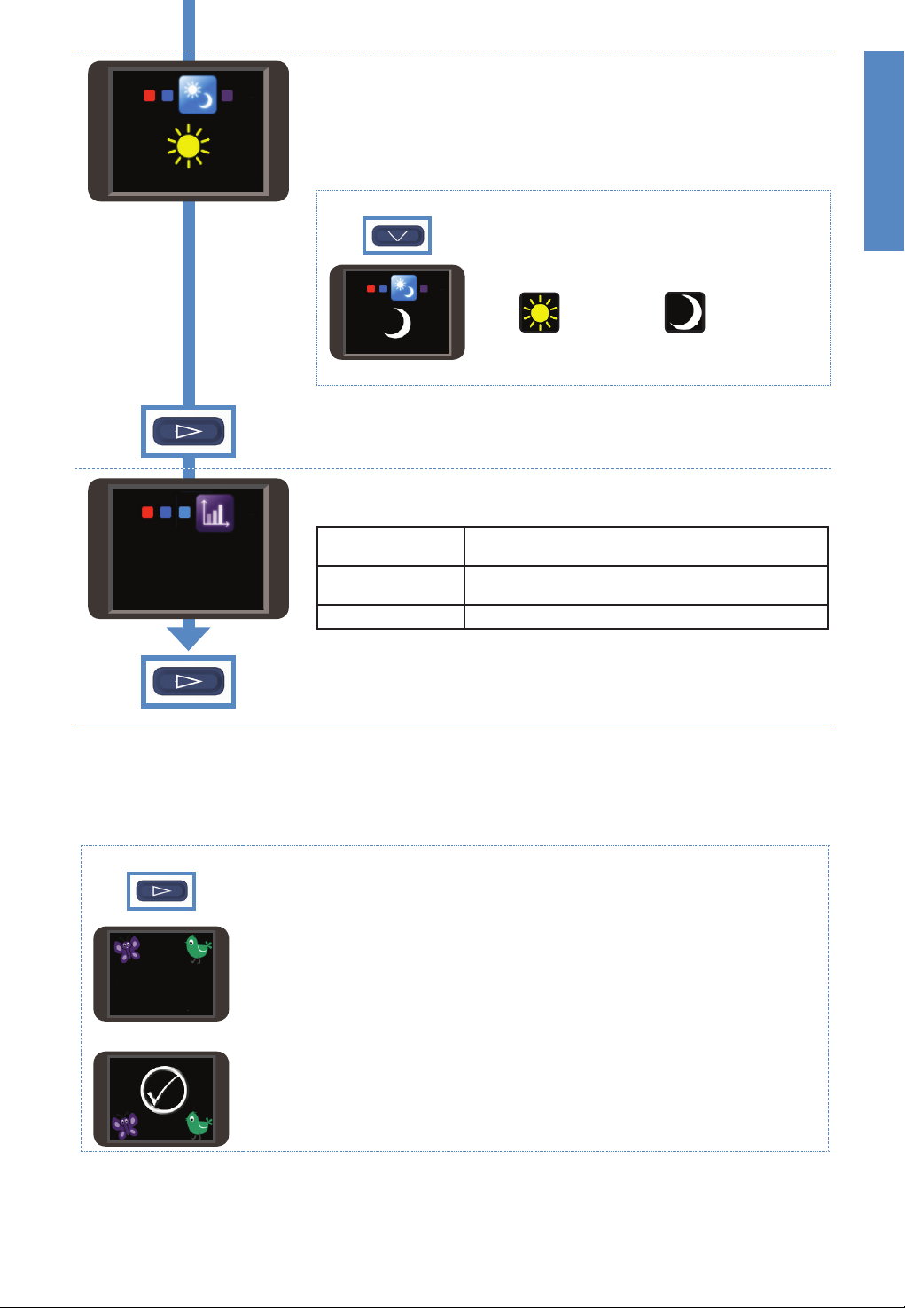
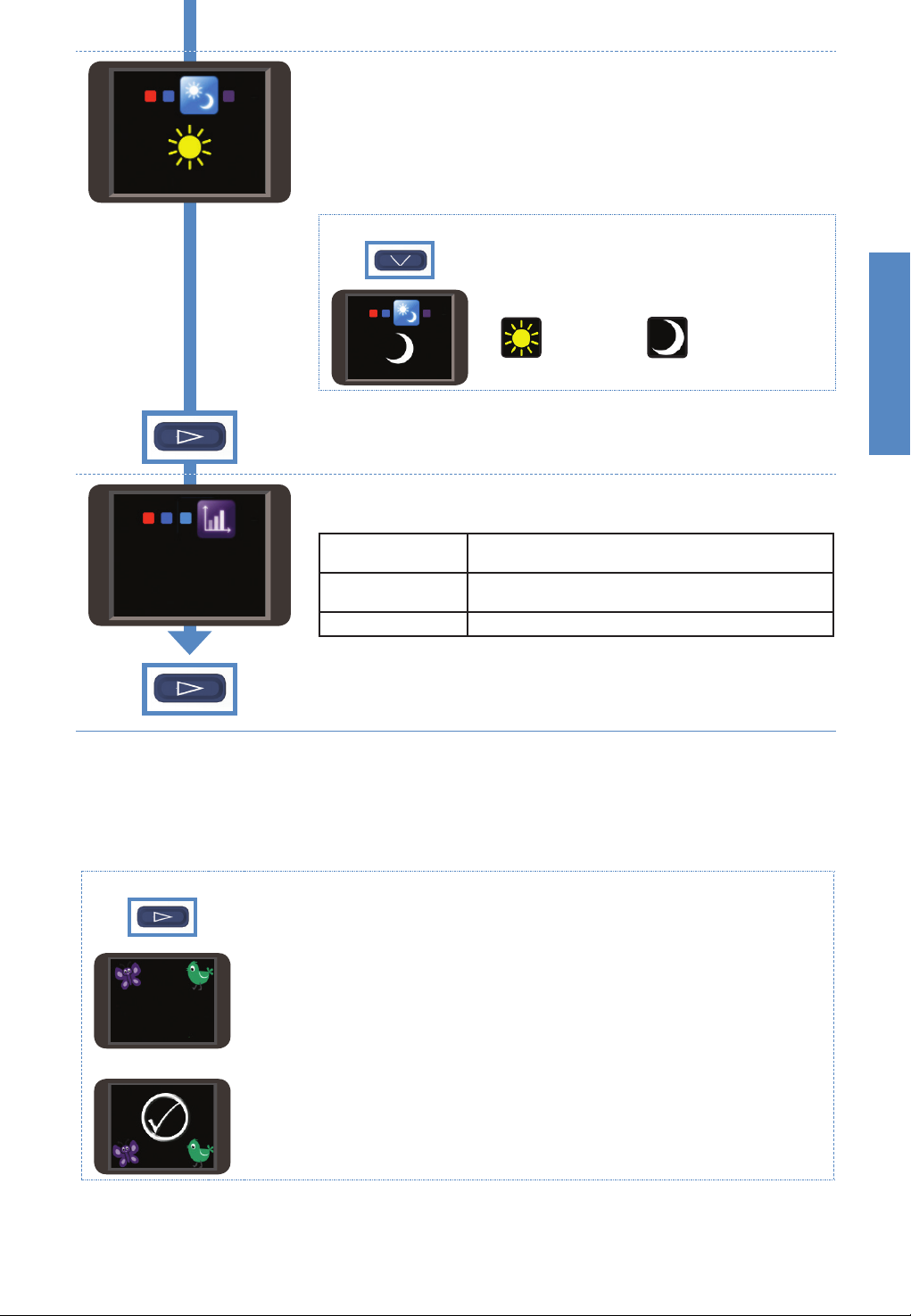
DAY/NIGHT MODES
You can set the myAIRVO 2 to “Day” mode or “Night” mode.
In “Night” mode, some of the myAIRVO 2 sounds will be made quieter.
The display will become dimmed. Alarms will be unaected.
The myAIRVO 2 will remember its Day/Night setting when you switch it
o.
To change the Day/Night setting:
Press the Up and Down buttons to choose the new
setting.
English
à
“Day”
à
“Night”
Press the Mode button to move on to the next screen.
COMPLIANCE
This screen displays three pieces of compliance data:
Total hours used
83
Total hours used
Hours per day
Checksum Displays usage information for the medical practitioner.
Displays the total number of hours that the unit has
been switched on.
Displays the average number of hours that the unit has
been used per day.
Press the Mode button to return to the “Warm-up”/”Ready for use”
screen.
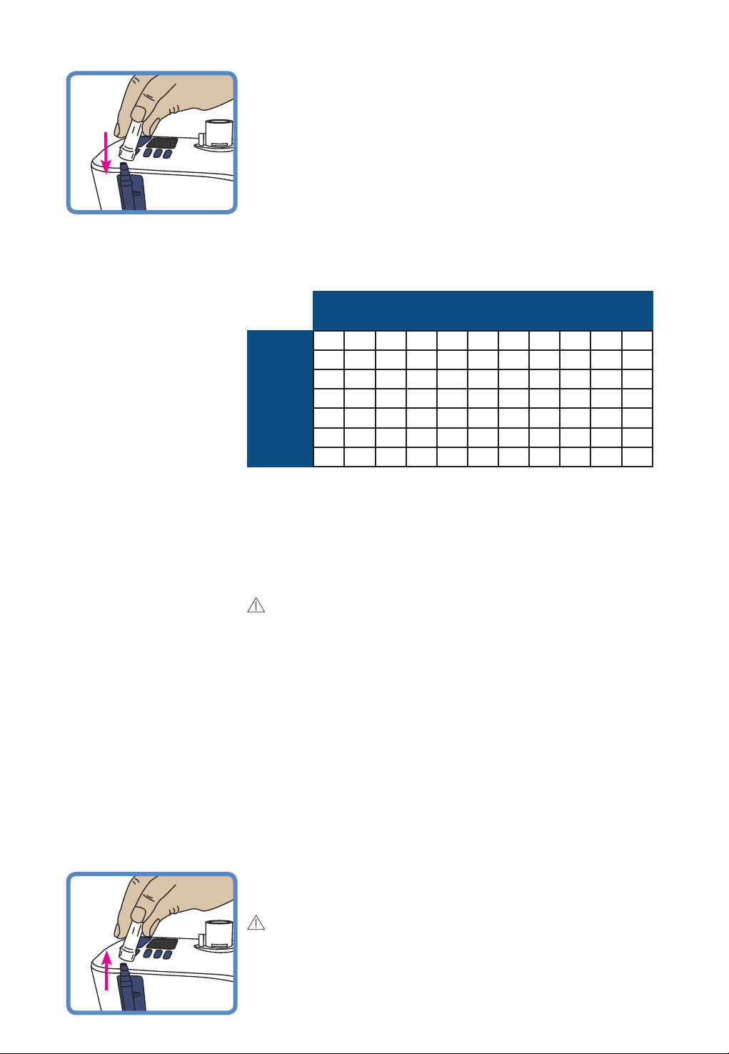
JUNIOR MODE
If the patient will be using an Optiflow Junior nasal cannula (OPT316/OPT318), you must activate Junior
Mode.
Junior Mode limits the target settings to: 34 °C and 2 - 25 L/min, in increments of 1 L/min.
To activate Junior Mode:
You must be able to see the “Warm-up” symbol or the “Ready for use” symbol to activate
Junior Mode.
Hold the Mode button for 5 seconds.
New target settings
New target
settings
The target settings for dew-point temperature and flow will be changed automatically. The
colorful icons in the corners of the screen indicate that this unit is in Junior Mode.
To deactivate Junior Mode, follow the same procedure: hold the Mode button for 5 seconds.
If you are unable to activate Junior Mode, it is possible that Junior Mode may not have been enabled for
your device. Contact your Fisher & Paykel Healthcare representative.
A – 9
OXYGEN
You can connect supplementary oxygen to the myAIRVO 2. Connect the
output from the oxygen source to the oxygen inlet port on the back of the
unit. Make sure you push the oxygen tube firmly onto this connection port.
The fraction of oxygen you breathe with this air/oxygen mixture is
determined by the airflow setting on the unit and the oxygen flow
connected to the unit’s oxygen inlet port.
The following table gives the approximate oxygen fraction delivered for
the range of unit and oxygen airflows. The oxygen fractions given assume
that the oxygen source is a home oxygen concentrator. These values will be
higher if the oxygen source is bottled oxygen. At flows less than 10 L/min,
the oxygen fraction delivered varies significantly with small changes in
input oxygen flow. Oxygen flow settings should be titrated according to
blood saturation levels.
myAIRVO 2 Target Flow Setting (L/min)
10 15 20 25 30 35 40 45 50 55 60
1 29 27 25 24 24 23 23 23 23 23 22
2 38 32 29 28 26 26 25 25 24 24 24
3 45 37 33 31 29 28 27 26 26 25 25
4 53 42 37 34 32 30 29 28 27 27 26
(L/min)
5 60 48 41 37 34 33 31 30 29 29 28
Oxygen Flow
7 75 58 50 44 40 37 35 34 32 31 31
10 93 74 61 54 49 45 42 39 37 36 35
It is important that the physician prescribing your oxygen therapy
approves both the flow and oxygen settings and that you do not adjust
these prescribed settings without consulting them.
Check that suitable blood saturation levels are achieved at the prescribed
flow.
Use continuous oxygen monitoring on patients who would desaturate
significantly in the event of disruption to their oxygen supply.
WARNINGS
Before using oxygen with the unit, read all of the following warnings:
• The use of oxygen requires that special care be taken to reduce the risk of fire.
Accordingly, for safety it is necessary that all sources of ignition be kept away from
the unit and preferably out of the room in which it is being used. Oxygen should
not be used while smoking or in the presence of an open flame. The unit should be
located in a position where ventilation around the unit is not restricted.
• A spontaneous and violent ignition may occur if oil, grease or greasy substances
come in contact with oxygen under pressure. These substances must be kept away
from all oxygen equipment.
• Do not connect more than 15 L/min O2 to the oxygen inlet port on the back of the
unit.
• Ensure that the myAIRVO 2 is switched on before connecting oxygen.
• Oxygen must only be added through the special oxygen inlet port on the back of
the unit. To ensure that oxygen enters the unit correctly, the oxygen inlet port must
be fitted properly to the filter holder and the filter holder must be fitted properly to
the unit. The power cord connector should also be well secured.
• The oxygen concentration delivered to the patient can be aected by changes to
the flow setting, oxygen setting, patient interface or if the airpath is obstructed.
When finished, turn o the oxygen source. Remove the output of the
oxygen source from the oxygen inlet port on the back of the unit.
WARNINGS
To avoid burns:
• The oxygen flow must be turned o when the unit is not operating, so that oxygen
does not build up inside the device.
A – 10
ALARMS
The myAIRVO 2 has visual and auditory alarms to warn you about interruptions to your treatment. These
alarms are generated by an intelligent alarm system, which processes information from the sensors and
target settings of the unit and compares this information to pre-programmed limits.
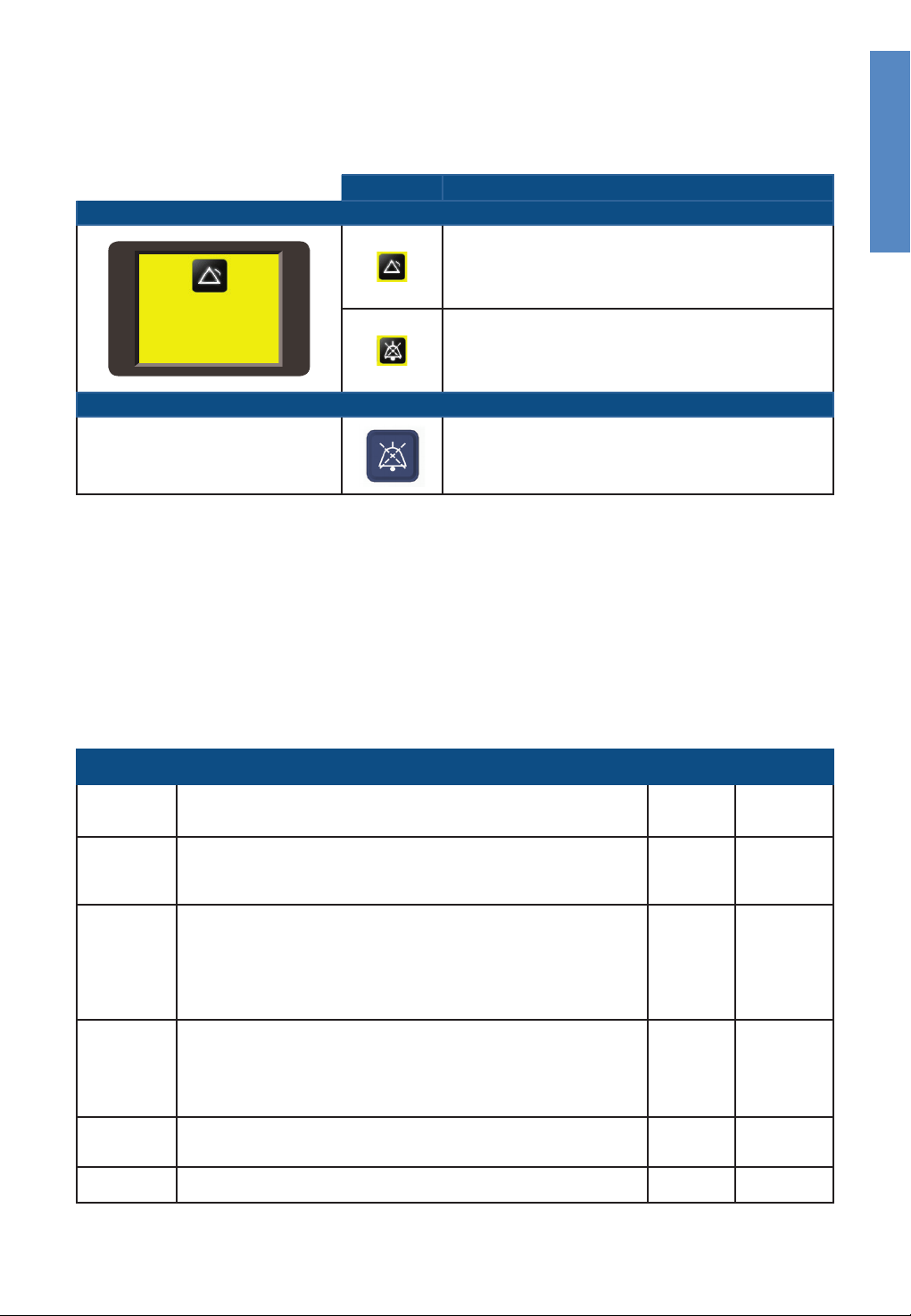
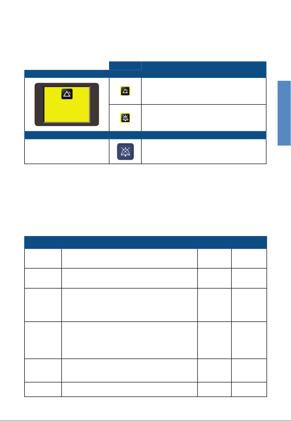
ALARM SIGNALS
Symbols Meaning
Visual alarm signal
Alarm condition.
(message)
Audio paused.
Auditory alarm signal
English
3 beeps in 3 seconds.
Repeated every 5 seconds.
Press this button to mute the auditory alarm for 115 seconds.
The auditory alarm can be reactivated by pressing this
button again.
ALARM CONDITIONS
All of the alarms listed below have been assessed as “Medium Priority”. These priorities have been
allocated for an operator’s position within 1 meter of the device. The unit also uses an internal priorityranking system. If multiple alarm conditions occur simultaneously, the unit will display the highest-priority
alarm.
The following table lists all of the alarm conditions from highest-priority to lowest priority, their causes,
possible solutions and delays. Alarm conditions that aect oxygen delivery require an immediate response
to assess the patient’s saturation levels. Alarm conditions that aect humidity delivery require a prompt
response to assess potential drying of mucus and associated blockages.
Message Meaning
Fault
(E###)
Check tube
Check for
leaks
Check for
blockages
O2 too low
O2 too high
The unit has detected an internal fault and has shut itself down.
Switch the unit o and then restart. If the problem persists, note the fault
code and contact your Fisher & Paykel Healthcare representative.
The unit cannot detect the heated breathing tube.
Check that the heated breathing tube is not damaged and that it is
plugged in correctly. If the problem persists, then change the heated
breathing tube.
The unit has detected a leak in the system.
The most likely cause is that the water chamber has been removed or has
not been pushed into place correctly.
Check that the heated breathing tube is not damaged and that it is
plugged in correctly.
Check that the nasal interface is fitted.
Check that the filter is fitted.
The unit has detected a blockage in the system.
Check the heated breathing tube or patient interface for blockage.
Check the air filter and filter holder for blockage.
Check whether the unit should be in Junior Mode. If the patient will be
using an Optiflow Junior nasal cannula (OPT316/OPT318), you must
activate Junior Mode.
The measured oxygen level has fallen below the allowed limit.
Check that the oxygen source is still correctly connected.
Adjust the level of oxygen from the oxygen source as necessary.
The measured oxygen level has exceeded the allowed limit.
Adjust the level of oxygen from the oxygen source as necessary.
Aects
delivery of:
Oxygen,
humidity.
Oxygen,
humidity.
Oxygen,
humidity.
Oxygen,
humidity.
Oxygen < 20 seconds
Oxygen < 20 seconds
Delays
< 5 seconds
< 5 seconds
< 5 seconds
< 10 seconds
A – 11

(continued)
Message Meaning
Cannot
reach target
flow
The unit cannot reach the target flow setting.
Check the heated breathing tube or patient interface for blockage.
Check whether the target flow setting is too high for the patient interface
being used (refer to “Setting up myAIRVO 2” - ”Select Patient Interface”).
The unit will choose appropriate new target settings. You will be prompted
for acknowledgement.
WARNINGS
• The oxygen concentration delivered to the patient can be aected by
changes to the flow setting. Adjust the level of oxygen from the oxygen
source as necessary.
Check water
Cannot
reach target
temperature
The chamber has run out of water.
If using the HC360 reusable chamber: Remove the chamber and refill.
If using the MR290 auto-fill chamber: When a chamber runs dry, the
chamber float may be damaged. Replace the chamber and water bag.
[Twenty seconds after the chamber is removed, the “Check for leaks” alarm
is activated (see above). When the chamber is replaced, the unit enters
Warm-up Mode and resumes normal operation.]
To ensure continual humidification, always ensure that the water chamber
and/or water bag are not allowed to run out of water.
The unit cannot reach the target temperature setting.
You will be prompted for acknowledgement.
The most likely cause for this is that the unit is operating at a high flow rate
in low ambient conditions. Consider decreasing the target flow setting.
WARNINGS
• The oxygen concentration delivered to the patient can be aected by
changes to the flow setting. Adjust the level of oxygen from the oxygen
source as necessary.
Check
operating
conditions
[Power out]
The unit has detected that it is operating in unsuitable ambient conditions.
Do not use the device when the ambient temperature is less than 10°C.
Do not use the device when the ambient temperature is greater than 30°C.
The unit has been disconnected from the mains power supply.
No visual alarm. The auditory alarm will sound for 120 seconds.
Aects
delivery of:
Oxygen
Humidity
Humidity
Humidity
Oxygen,
humidity.
Delays
10 +/- 1
minutes
Flows above
20 L/min:
< 20 minutes
Flows of
and below
20 L/min:
< 40 minutes
30 +/- 3
minutes
60 +/- 6
seconds
< 5 seconds
ALARM LIMITS
Most alarm limits are pre-programmed. The exceptions are listed below. These alarm limits may be
changed to other values by authorized personnel. Changes will be preserved during or after any power
loss.
Alarm
condition
O2 too low
O2 too high
Factory-set
alarm limit
21% O
2
90% O
2
Possible preset
values
21 – 25% O
30 – 90% O
2
2
WARNINGS
• A hazard can exist if dierent alarm presets are used on dierent units within any single area, eg. long term care facility
• Alarm limits set to extreme values can render the alarm system useless.
CHECKING ALARM SYSTEM FUNCTIONALITY
The functionality of the alarm system can be checked at any time when the unit is turned on.
Remove the heated breathing tube. You should see the “Check tube” visual alarm signal and hear the
auditory alarm signal. If either alarm signal is absent, do not use the unit. Contact your Fisher & Paykel
Healthcare representative.
AUDITORY INFORMATION SIGNALS
In addition to auditory alarm signals, auditory information signals are provided. These are described below.
Melody Meaning
Ascending sequence of 5 tones The “Ready for use” symbol has appeared
Ascending sequence of 3 tones Activation/deactivation of Junior Mode
Decending scale of 3 tones (within 2 seconds) Drying Mode has been activated
Single tone every 5 seconds Measured oxygen level > 32% at turn-o
A – 12

4. CLEANING AND MAINTENANCE
It is important to carefully follow the instructions in this section, to keep the device clean and safe for use
and to extend the life of the consumables.
The following instructions are for single-patient home use. If the unit is ever used by multiple patients, the
unit must be cleaned and disinfected between patients according to instructions in the Disinfection Kit
Manual (900PT600). In addition, the patient interface, heated breathing tube and water chamber must be
changed between patients.
Standard aseptic techniques to minimize contamination should be followed when handling the unit
and accessories. This includes proper hand-washing, avoiding hand contact with connection ports, safe
disposal of the used consumables and suitable storage of the unit after cleaning and disinfection.
DAILY CLEANING INSTRUCTIONS
Run Drying Mode / Rinse the patient interface and water chamber
1. Allow Drying Mode to run after use (refer “Using myAIRVO 2” - “Drying Mode”).
2. Remove the interface, clean and rinse in drinking-quality water then reconnect to the heated breathing
tube whilst still in Drying Mode to dry the interface.
3. After Drying Mode is complete, remove the water chamber by pushing down the finger guard and
pulling out the chamber. Wash and rinse the chamber then refill it with sucient distilled water for the
next use.
WEEKLY CLEANING INSTRUCTIONS
Clean the patient interface, water chamber and myAIRVO 2
1. Switch o the unit and unplug from the power socket.
2. Remove the heated breathing tube and drain any excess condensate.
3. Remove the interface from the heated breathing tube, wash it in warm water with mild dishwashing
detergent added, rinse it in drinking-quality water, then reconnect it to the heated breathing tube.
4. Remove the water chamber.
English
If using the HC360 reusable chamber:
Pour out and discard the remaining water. Remove the chamber base.
Wash the chamber top and base in mild dishwashing detergent then
rinse. Soak the chamber in a solution of vinegar (1 part) and water (2
parts) for 10 minutes. Rinse and dry.
If using the MR290 chamber:
Do not wash this chamber. Carefully put the MR290 chamber aside.
5. Thoroughly wipe the inside of the heated breathing tube connection port with a clean, low-lint cloth
dipped in warm water with mild dishwashing detergent added.
6. Wipe the exterior of the unit with a clean, damp (not wet) cloth dipped in warm water with mild
dishwashing detergent added. Do not use harsh abrasives or solvents, as these may damage the unit.
7. Refit the heated breathing tube.
8. If using the HC360 chamber: Refit the chamber.
9. If using the MR290 chamber: Refit the MR290 chamber and reconnect to the water bag. Check that
water flows into the chamber and is maintained below the fill line. If the water level rises above the fill
line, replace the chamber immediately
10. Reconnect the unit to the power supply.
11. The unit is now ready for another week of use.
A – 13
SCHEDULE FOR CHANGING ACCESSORIES
The accessories for the unit must be changed frequently to avoid the risk of infection. Parts should be
replaced immediately if they are damaged or discolored; otherwise they must be replaced within the
periods shown in the following table. These periods assume that the correct daily and weekly cleaning
procedures and maintenance schedule described above are adhered to. These accessories are for singlepatient use only.
Maximum
period of use
Optiflow Junior interfaces
1 week
OPT316 / OPT316E Nasal Cannula - Infant
OPT318 / OPT318E Nasal Cannula - Pediatric
All other patient interfaces
OPT842 / OPT842E Nasal Cannula - Small
1 month
OPT844 / OPT844E Nasal Cannula - Medium
OPT846 / OPT846E Nasal Cannula - Large
OPT870 / OPT870E Tracheostomy Interface
RT013 / RT013E Mask Interface Adapter - 22mm
All tube & chamber kits
900PT500 / 900PT500E Heated breathing tube
2 months
3 months
or
900PT530E Heated breathing tube (for use with OPT316/OPT318 only)
900PT290E MR290 auto-fill chamber and adapter
900PT501 Heated breathing tube, MR290 auto-fill chamber and adapter
900PT531 Heated breathing tube, MR290 auto-fill chamber and adapter
(for use with OPT316/OPT318 only)
900PT913 Air filter
(or more often if significantly discolored)
1000 hours
Reusable
HC360 Reusable water chamber
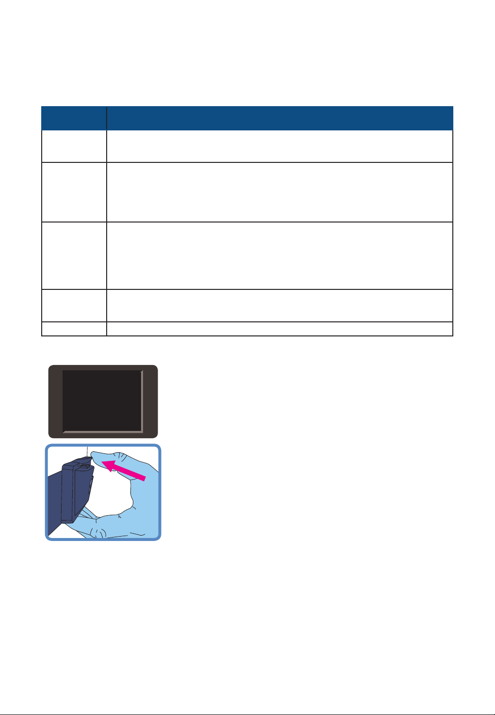
FILTER REPLACEMENT
Air lter change
due
Part number and description
If the unit tells you that a filter change is due:
1. Take the filter holder from the back of the unit and remove the filter.
2. Replace the old filter with a new one.
3. Reattach the filter holder to the unit (clip the bottom of the filter
holder in first, then rotate it upwards until the top clips into place).
4. Press the Mode button to move on to the next screen.
SERVICING
This device contains no serviceable parts.
A – 14
5. TECHNICAL INFORMATION
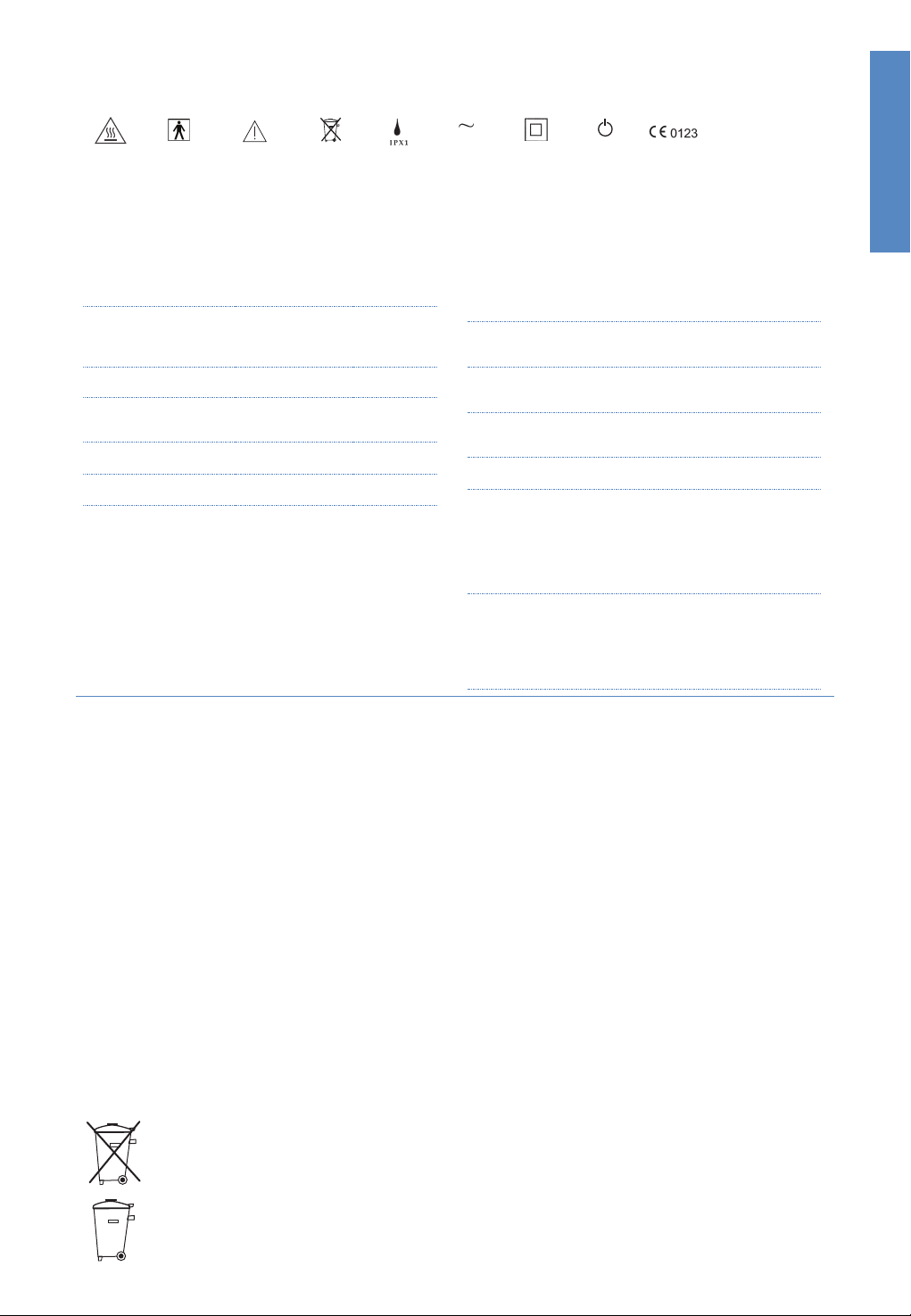
SYMBOL DEFINITIONS
Caution
Hot Surfaces
Type BF
Applied Part
ATTENTION
Consult
accompanying
documents
Do not
throw away
Drip Proof Alternating
PRODUCT SPECIFICATIONS
Dimensions 295 mm x 170 mm x 175 mm
Weight 2.2 kg (4.8 lb) unit only,
Supply frequency 50-60 Hz
Supply voltage/current 100-115 V 2.2 A (2.4 A max)
Sound pressure level
Auditory alarm pause
Serial port The serial port is used for
(11.6” x 6.7” x 6.9”)
3.4 kg (7.5 lb) packaged in bag
incl. accessories
220-240 V 1.8 A (2.0 A max)
Alarms exceed 45 dbA @ 1 m
115 seconds
downloading product data,
using F&P Infosmart™ software.
Current
Class ll
Double
Insulated
Power
On/Off
(Standby)
93/42/EEC
Class IIa
Humidity >33 mg/L at 37 °C target
>10 mg/L at 34 °C target
>10 mg/L at 31 °C target
Maximum temperature
of delivered gas
Maximum flow range
(default)
Maximum flow range
(Junior Mode)
Maximum oxygen input
43 °C (109 °F)
10-60 L/min
2-25 L/min
60 L/min
Warm-up time 10 minutes to 31 °C (88 °F),
30 minutes to 37 °C (98.6
°F) using a MR290 chamber
with flow rate of 35 L/min and
starting temperature 23 ± 2 °C
(73 ± 3 °F)
Oxygen analyzer
accuracy
< ± (2.5% + 2.5% of gas level)
(within the range 25-95% O2)
Operating conditions:
18-28 °C (64-82 °F),
30-70% RH
English
Designed to conform to the requirements of:
IEC 60601-1
UL 60601-1
CSA C22.2/No. 601.1
AS 3200.1.0
EN 60601-1
The unit complies with the electromagnetic compatibility requirements of IEC 60601-1-2. In
certain circumstances, the unit may aect or be aected by nearby equipment due to the
eects of electromagnetic interference. If this should happen, try moving the unit or the
location of the unit causing interference, or alternatively consult your healthcare provider.
Accessory equipment connected to the serial port of the device must be certified to either IEC 60601-1 or IEC
60950-1. Furthermore all configurations shall comply with the system standard IEC 60601-1-1. Anyone who connects
additional equipment to the signal input part or signal output part configures a medical system and is therefore
responsible for ensuring that the system complies with the requirements of the system standard IEC 60601-1-1. If in
doubt, consult the technical services department or your local representative.
OPERATING CONDITIONS
Ambient temperature 18 to 28 °C (64 to 82 °F)
Humidity 10 to 95% RH
Altitude 0 to 2000 m (6000 ft)
Mode of operation Continuous operation
STORAGE AND TRANSPORT CONDITIONS
The unit should be stored and transported in environmental conditions of -10 °C to 60 °C (14 °F to 140 °F),
10 to 95% RH, non-condensing.
DISPOSAL INSTRUCTIONS
Unit Disposal Instructions
This unit contains electronics. Please do not discard with regular waste. Return to Fisher & Paykel
Healthcare or dispose according to local guidelines for disposing of electronics. Dispose according to Waste
Electrical and Electronic Equipment (WEEE) directive in European Union.
Consumables Disposal Instructions
Place the interface, breathing tube and chamber in a bag at the end of use and discard with regular waste.
A – 15

ERSTE SCHRITTE
• Diese Bedienungsanleitung ist für Patienten bestimmt.
• Diese Bedienungsanleitung gilt für myAIRVO 2-Einheiten mit mit einer Charge 130621 oder höher.
• Lesen Sie diese Bedienungsanleitung einschließlich sämtlicher Warnhinweise. Andernfalls kann es zu
Verletzungen kommen. Sehen Sie sich außerdem die myAIRVO2-Videoanleitung an. Bewahren Sie beides
zur späteren Einsichtnahme auf.
• Bevor der myAIRVO 2 zum ersten Mal angewendet wird, muss er gemäß den Anweisungen im Technischen
Handbuch des myAIRVO 2 eingerichtet werden. Dies sollte durch medizinisches Fachpersonal oder einen
Medizintechniker durchgeführt werden.
• Sollte der Fall eintreten, dass das Gerät von mehreren Patienten genutzt wird, ist das Gerät nach jedem
Patienten zu reinigen und zu desinfizieren. Dabei ist die Bedienungsanleitung für das Desinfektions-Kit zu
beachten.
• Für weitere Beratung wenden Sie sich bitte an Ihre Fisher & Paykel Healthcare Vertretung.
INHALTSVERZEICHNIS
1. Übersicht ....................................................................................................................................................... B - 2
Verwendungszweck .................................................................................................................................................................. B - 2
Warnhinweise ................................................................................................................................................................................ B - 2
myAIRVO 2 und Zubehör ........................................................................................................................................................ B - 3
2. Einrichten des myAIRVO 2 ................................................................................................................... B - 4
3. Betrieb des myAIRVO 2 ......................................................................................................................... B - 7
Erweiterte Einstellungen ........................................................................................................................................................... B - 8
Sauersto ....................................................................................................................................................................................... B - 10
Alarme ............................................................................................................................................................................................. B - 11
Deutsch
4. Reinigung und Wartung ......................................................................................................................... B - 13
Tägliche Reinigung ..................................................................................................................................................................... B - 13
Wöchentliche Reinigung ......................................................................................................................................................... B - 13
Zeitplan für das Auswechseln des Zubehörs .................................................................................................................... B - 14
Auswechseln des Filters............................................................................................................................................................ B - 14
Wartung .......................................................................................................................................................................................... B - 14
5. Technische Daten ..................................................................................................................................... B - 15
B – 1

1. ÜBERSICHT
Der myAIRVO 2 ist ein Atemgasbefeuchter mit integriertem Flowgenerator, der spontan atmenden Patienten
über verschiedene Patientenschnittstellen, angewärmte und befeuchtete Atemgase zuführt.
VERWENDUNGSZWECK
Der myAIRVO 2 ist für die Behandlung von spontan atmenden Patienten geeignet, die von der Zufuhr
von erwärmten, befeuchteten High-Flow-Atemgasen profitieren können. Das Gerät ist auch für Patienten
geeignet, deren obere Atemwege umgangen wurden. Je nach Patienten-Interface kann die Flowrate
2-60 L/min betragen. Der myAIRVO 2 ist für Patienten zu Hause und in Langzeitpflegeeinrichtungen
vorgesehen.
Laut US-Bundesgesetz darf dieses Gerät nur vom einem Arzt oder auf ärztliche Anordnung verkauft werden.
WARNHINWEISE
!
• Die nasale Zufuhr von Atemgasen führt zu einem Flow-abhängigen positiven Atemwegsdruck (PAP). Dies
muss beachtet werden, wenn PAP unerwünschte Ereignisse für den Patienten auslösen könnte.
• Das Gerät dient nicht der künstlichen Lebenserhaltung.
Um Verbrennungen vorzubeugen:
• Das Gerät ist nur mit den in dieser Bedienungsanleitung empfohlenen Patientenschnittstellen,
Wasserkammern und Beatmungsschläuchen zu verwenden.
• Eine schwere Verletzung, einschließlich Infektion, kann auftreten, wenn Beatmungsschlauch oder
Patienten-Interface über den angegebenen Zeitraum hinaus benutzt werden.
• Vor der Verwendung des Geräts mit Sauersto lesen Sie bitte alle Warnungen im Abschnitt „Sauersto“
dieser Bedienungsanleitung.
• Benutzen Sie das Gerät keinesfalls, wenn:
• der beheizte Beatmungsschlauch beschädigt ist und Löcher, Risse oder Knicke aufweist,
• das Gerät nicht ordnungsgemäß funktioniert,
• die Gehäuseschrauben gelockert wurden.
• Der Luftdurchfluss durch Gerät und Schlauch darf nicht behindert werden.
• Das Gerät sollte so aufgestellt werden, dass es von allen Seiten gut belüftet ist.
• Die Belüftungsönungen des Gerätes dürfen keinesfalls blockiert sein. Stellen Sie das Gerät darum nicht
auf weiche Unterlagen, z. B. Bett oder Sofa, wo der Filterbereich blockiert werden kann. Sorgen Sie dafür,
dass die Önungen frei von Fusseln, Haaren, usw. sind.
Um Stromschläge zu vermeiden:
• Das Gerät sollte nicht an einem Ort aufbewahrt oder benutzt werden, wo es ins Wasser fallen oder
gezogen werden kann. Wenn Wasser in das Gerät eingedrungen ist, ziehen Sie sofort das Netzkabel aus
der Steckdose und benutzen Sie es nicht mehr.
• Benutzen Sie das Gerät keinesfalls, wenn:
• das Gerät fallen gelassen wurde oder beschädigt ist,
• Netzkabel oder Stecker beschädigt ist,
• das Gerät ins Wasser gefallen ist.
• Vermeiden Sie die unnötige Trennung des Netzkabels von der Rückseite des Geräts. Wenn eine Trennung
nötig ist, halten Sie den Anschluss beim Herausziehen fest. Nicht direkt am Netzkabel ziehen.
• Abgesehen von den nachstehend beschriebenen Fehlern bringen Sie das Gerät zur Prüfung und Reparatur
stets zu einem autorisierten Kundendienstzentrum.
Um der Gefahr des Erstickens oder Inhalierens eines Fremdkörpers vorzubeugen:
• Achten Sie darauf, dass beim Betrieb des Gerätes ein Luftfilter vorhanden ist.
• Es dürfen keinerlei Gegenstände in den Schlauch bzw. die Önungen eingeführt werden.
Sonstiges Zubehör:
• Benutzen Sie das Gerät nicht bei Zimmertemperaturen über 30 °C (86 °F) oder unter 10 °C (50 °F), da es
sich selbsttätig ausschalten könnte. Bei Temperaturen unter 18 °C (64 °F) und über 28 °C (82 °F) ist die
Feuchtigkeitsabgabe beeinträchtigt.
• Das Gerät ist nicht für den Gebrauch in Gegenwart entflammbarer Narkosegasmischungen mit Luft oder
Sauersto oder Distickstomonoxid geeignet.
B – 2
myAIRVO 2 UND ZUBEHÖR
AN/AUS (STANDBY)
AUDIO PAUSE
HOCH
RUNTER
MODUS
Patienten-
Interface
DISPLAY
WASSERBEUTEL
SAUERSTOFF-
EINLASS
KOMPAKTSTÄNDER
SERIELLER
PORT
NETZKABEL und
ANSCHLUSSSTECKER
FILTERABDECKUNG
LUFTFILTER
myAIRVO 2
Schlauch- u. Kammersets und Patienten-Interfaces
Schlauch- u. Kammersets Interfaces
900PT531
900PT530E
900PT290E
HC360 Wiederverwendbare Wasserkammer
900PT500
900PT500E
900PT501
900PT290E
HC360 Wiederverwendbare Wasserkammer
Beheizter Beatmungsschlauch,
selbstbefüllende Kammer MR290 mit
Adapter (10er-Packung)
Beheizter Beatmungsschlauch
(1er-Packung)
Selbstbefüllende Kammer MR290 mit
Adapter (1er-Packung)
Beheizter Beatmungsschlauch
(10er-Packung)
Beheizter Beatmungsschlauch
(1er-Packung)
Beheizter Beatmungsschlauch,
selbstbefüllende Kammer MR290 mit
Adapter (10er-Packung)
Selbstbefüllende Kammer MR290 mit
Adapter (1er-Packung)
(PT100EW)
Beheizter
Beatmungs-
schlauch
ADAPTERANSCHLUSS FÜR DEN
BEHEIZTEN BEATMUNGSSCHLAUCH
KAMMERANSCHLÜSSE
HEIZ-
PLATTE
FINGER-
SCHUTZ
Wasserkammer
WIEDERVERWENDBARE
WASSERKAMMER
(HC360)
OPT316 Nasenkanüle - Kleinkind (20er-Packung)
à
OPT318 Nasenkanüle - Kind (20er-Packung)
OPT842 Nasenkanüle - klein (20er-Packung)
OPT844 Nasenkanüle - mittel (20er-Packung)
OPT846 Nasenkanüle - groß (20er-Packung)
à
OPT870
RT013 Maskenadapter (20er-Packung)
-E (1-er Packung) z. B. OPT870E
Tracheostomie-Direktanschluss
(20er-Packung)
SELBSTBEFÜLLENDE
WASSERKAMMER
(MR290; mit Adapter)
Deutsch
Sonstiges Zubehör
900PT400 Kompakter Ständer (für myAIRVO 2 und Wasserbeutel)
900PT401 Wasserbeutel (2er-Packung)
900PT422 Sauerstozufuhrsatz mit Verlängerung
900PT912 Filterhalter
900PT913 Luftfilter (2er-Packung)
OPT012 Wigglepads (OPT316/OPT318) (20er Packung)
OPT014 Sauerstoschlauch (Optiflow Junior)
B – 3
2. EINRICHTEN DES myAIRVO 2
H2O
1. ERSTE SCHRITTE
Stellen Sie das Gerät auf ein niedriges Regal oder auf den Boden neben
Ihrem Bett. Das Gerät ist unterhalb der Kopfhöhe zu platzieren und muss
waagerecht stehen.
2. WASSERKAMMER BEFESTIGEN
BEI VERWENDUNG EINER WIEDERVERWENDBAREN
WASSERKAMMER HC360:
Füllen Sie mit dem mitgelieferten Trichter ausreichend destilliertes Wasser
für die Betriebsdauer in die Kammer ein. Der Wasserstand darf dabei nicht
über die Markierung von 560mL steigen.
HC360: Flow-Einstellungen vs. Betriebszeit
L/min
WARNHINWEISE
Um Verbrennungen vorzubeugen:
• Die Wasserkammer nicht mit heißem Wasser füllen.
Um Stromschläge zu vermeiden:
• Nehmen Sie die Wasserkammer zum Befüllen stets ab und füllen Sie ausreichend
destilliertes Wasser ein, so dass das Wasser nicht ausgeht.
2 5 10 15 20 25 30 35 40 45 50 55 60
106 42 21 14 11 8 7 6 5 5 4 4 4
Std
Zum Aufsetzen der Wasserkammer auf das Gerät drücken Sie den
Fingerschutz herunter und schieben Sie die Kammer auf. Achten Sie
dabei auf die blauen Kammeranschlüsse.
Schieben Sie die Kammer fest auf, bis der Fingerschutz einrastet.
Fahren Sie mit Schritt 3 („Einsetzen des beheizten
Beatmungsschlauchs“) fort.
BEI VERWENDUNG DER SELBSTBEFÜLLENDEN
WASSERKAMMER MR290:
Nehmen Sie die blauen Portkappen von der Kammer ab, indem Sie
die Abrisslasche nach oben ziehen. Dann nehmen Sie den Halter des
Wasserzufuhrschlauches ab. Setzen Sie den mitgelieferten Adapter fest
auf die beiden vertikalen Kammeranschlüsse auf und befestigen Sie den
Wasserzufuhrschlauch an der dafür vorgesehenen Stelle.
Setzen Sie die Wasserkammer MR290 so auf, wie oben für die Kammer
HC360 beschrieben.
Hängen Sie den Wasserbeutel etwa 20cm (8 in.) oberhalb des
Gerätes an den Haken und stecken Sie den Dorn in das Röhrchen an
der Beutelunterseite ein. Önen Sie die Belüftungskappe an der Seite
des Beuteldorns. Nun befüllt sich die Kammer automatisch bis zum
erforderlichen Stand, der erhalten bleibt, bis der Wasserbeutel leer
ist. Benutzen Sie nur destilliertes Wasser und sorgen Sie stets für eine
ausreichende Wassermenge im Wasserbeutel, damit das Gerät nicht
trocken läuft.
B – 4
Prüfen Sie, dass Wasser in die Kammer fließt und der Wasserstand
unterhalb der Markierung bleibt. Sollte der Wasserstand bis über die
Markierung steigen, muss die Kammer umgehend gewechselt werden.
MR290: Flussrate/Betriebszeit
(Wasserbeutel 900PT401, 1000 mL)
L/min
Std
2 5 10 15 20 25 30 35 40 45 50 55 60
189 76 38 25 19 15 13 11 9 8 8 7 6
WARNHINWEISE
Um Verbrennungen vorzubeugen:
• Das Gerät darf nicht eingeschaltet werden, wenn die Wasserkammer nicht
aufgesetzt ist.
• Das Berühren von Heizplatte, Wasserkammer und Kammerbasis ist während des
Betriebs zu vermeiden.
• Das in der Kammer befindliche Wasser heizt sich während des Betriebs auf. Beim
Abnehmen und Entleeren der Kammer ist deshalb Vorsicht angezeigt.
Um Stromschläge zu vermeiden:
• Wenn das Gerät mit gefüllter Wasserkammer bewegt wird, sollte es nicht geneigt
werden, damit kein Wasser in das Gehäuse eindringen kann.
• Vor dem Transport des Gerätes ist die Wasserkammer vollständig auszuleeren.
VORSICHTSHINWEISE
Um die optimale Therapie sicherzustellen (Nur MR290):
• Die selbstbefüllende Kammer MR290 darf nicht verwendet werden, wenn sie
fallen gelassen wurde oder trocken gelaufen ist, so dass der Alarm „Kammer leer“
ausgelöst wurde.
3. EINSETZEN DES BEHEIZTEN BEATMUNGSSCHLAUCHS
An einem Ende des beheizten Beatmungsschlauches befindet sich eine
blaue Kunststomanschette. Heben Sie die Manschette an und schieben
Sie den Adapter auf das Gerät. Schieben Sie die Manschette wieder
herunter, um den Verschluss herzustellen.
WARNHINWEISE
Um Verbrennungen vorzubeugen:
• Beatmungsschlauch und Interface dürfen in keiner Weise modifiziert werden.
• Den Beatmungsschlauch nicht für längere Zeit in direkten Kontakt mit der Haut
kommen lassen.
• Eine schwerwiegende Verletzung kann auftreten, wenn das Patienten-Interface
auf mehr als Zimmertemperatur erwärmt wird, z. B. durch eine Decke oder
Erhitzen in einem Inkubator oder Platzierung unter einem Heizstrahler für
Neugeborene.
• Benutzen Sie keine Isoliermanschette oder ähnliches Zubehör, das nicht von
Fisher & Paykel Healthcare empfohlen wurde.
VORSICHTSHINWEISE
• Positionieren Sie den beheizten Beatmungsschlauch, entfernt von jeglichen
elektronischen Überwachungs-Elektroden (EEG, EKG, EMG usw.), um eine
mögliche Interferenz mit dem überwachten Signal zu minimieren.
Deutsch
B – 5

4. AUSWÄHLEN DES PATIENTEN-INTERFACE
Der myAIRVO 2 eignet sich für verschiedene Patienten-Interfaces. Lesen Sie die separate
Bedienungsanleitung für das verwendete Patienten-Interface, einschließlich sämtlicher Warnhinweise.
WARNHINWEISE
Um Verbrennungen vorzubeugen:
• Beatmungsschlauch und Interface dürfen in keiner Weise modifiziert werden.
• Es dürfen nur die hier genannten Interfaces verwendet werden.
(OPT842/OPT844/OPT846)
Nasenkanüle
Bei Verwendung des Nasal-Interface legen Sie dem Patienten
bitte die Halteschlaufe um den Hals. Halten Sie das NasalInterface in der Nase fest und legen Sie sich das Gummiband
oberhalb der Ohren um den Kopf. Das Gummiband kann an den
Seiten nachgestellt werden.
Nasenkanüle
(OPT316/OPT318)
Siehe separate Bedienungsanleitung.
Tracheostomie-Interface
(OPT870)
Bei Verwendung des Tracheostomie-Interface legen Sie dem
Patienten bitte die Halteschlaufe um den Hals, schließen den
Adapter des Tracheostomie-Tubus wie abgebildet an und
stellen die Länge des Bandes passend ein.
Maskenadapter
(RT013)
Bei Verwendung einer belüfteten StandardTracheostomiemaske oder Gesichtsmaske schließen Sie den
22-mm-Adapter der Maske an den RT013- Maskenadapter an.
Legen Sie dem Patienten die Halteschlaufe um den Hals und
setzen Sie die Maske wie gewohnt auf.
WARNHINWEISE
• Bitte beachten Sie, dass der RT013-Maskenadapter nur für belüftete
Masken vorgesehen ist. Unbelüftete Masken dürfen damit nicht
benutzt werden.
B – 6
3. BETRIEB DES myAIRVO 2
1. GERÄT EINSCHALTEN
Schließen Sie das Netzkabel des Geräts an das Stromnetz an. Der
Stecker am anderen Ende des Netzkabels sollte gut an der Rückseite
des Geräts gesichert sein.
WARNHINWEISE
Um Stromschläge zu vermeiden:
• Vergewissern Sie sich, dass das Gerät trocken ist, bevor es an die
Stromversorgung angeschlossen wird.
Zum Einschalten des Geräts betätigen Sie die Ein/Aus-Taste.
2. AUFWÄRMEN
Das Gerät beginnt sich aufzuwärmen. Auf dem Display sehen Sie dabei
ein Aufwärmsymbol.
Aufwärmsymbol
Deutsch
3. PATIENTENINTERFACE ANSCHLIESSEN
„Betriebsbereit“-Symbol
Sobald das Symbol „Betriebsbereit“ auf dem Display erscheint, können
Sie das Patienten-Interface an den beheizten Beatmungsschlauch
anschließen. Die Trageschlaufe festziehen, um das Gewicht vom
beheizten Beatmungsschlauch zu nehmen.
Beim erstmaligen Gebrauch des Gerätes fühlt sich die Luft warm an.
Atmen Sie weiterhin normal.
4. NACH GEBRAUCH
Nach Gebrauch des Geräts nehmen Sie Ihr Interface ab und lassen Sie
überschüssiges Kondenswasser aus dem Beatmungsschlauch ablaufen.
Heben Sie dazu das Patientenende des Schlauchs an, damit das
Kondenswasser in die Wasserkammer abfließt.
5. TROCKNUNGSMODUS
Halten Sie anschließend die Ein/Aus-Taste 3Sekunden lang gedrückt, bis
eine Melodie ertönt. Das Gerät startet automatisch den Trocknungsmodus
und trocknet den Schlauch, damit er für die nächste Therapiesitzung
einsatzbereit ist. Der Trocknungsmodus läuft 99 Minuten. Nach dessen
Beendigung schaltet sich das Gerät automatisch aus.
WARNHINWEISE
Um Verbrennungen vorzubeugen:
• Tragen Sie das Patienten-Interface nicht während des Trocknungsmodus.
Es besteht Verletzungsgefahr durch heiße, trockene Luft.
• Entfernen Sie die Wasserkammer erst nach dem vollständigen Durchlaufen des
Trocknungsmodus.
Zum Abschalten des Geräts ohne vollständigen Durchlauf des
Trocknungsmodus (nicht empfohlen), die Ein/Aus-Taste 5 Sekunden
gedrückt halten.
Wenn Sie das Netzkabel des Geräts während des laufenden Betriebs
vom Stromnetz trennen, ertönt der Alarm „Strom aus“. Durch Drücken
der Taste „Audio Pause“ können Sie diesen Alarm unterdrücken.
B – 7

ERWEITERTE EINSTELLUNGEN
Wenn das Aufwärmsymbol oder das „Betriebsbereit“-Symbol angezeigt
wird, können Sie durch Drücken der Modus-Taste auf die erweiterten
Einstellungen zugreifen.
SOLL-TAUPUNKTTEMPERATUR
Beim myAIRVO 2 können Sie drei Soll-Taupunkttemperaturen einstellen:
• 37 °C (98,6 °F)
• 34 °C (93 °F) (falls Compliance bei 37 °C problematisch ist)
• 31 °C (88 °F) (nur für Gesichtsmasken).
Unter folgenden Bedingungen können Sie u. U. nicht auf alle
Einstellungen zugreifen:
• Gerät befindet sich im Junior-Modus (begrenzt auf 34 °C),
• Gerät wurde ursprünglich mit engeren Grenzwerten eingerichtet.
Der myAIRVO 2 speichert die eingestellte Soll-Taupunkttemperatur,
wenn Sie das Gerät ausschalten.
Ändern der Soll-Taupunkttemperatur:
Drücken Sie die Pfeiltasten (oben/unten), um einen
neuen Wert einzustellen.
Die große Zahl in der Mitte des Bildschirms zeigt die
von Ihnen gewählte Einstellung an.
Die kleinen Zahlen beim Pfeil zeigen die verfügbaren
Mindest- und Höchstwerte an.
Durch Drücken der Modus-Taste gelangen Sie zum nächsten Schirm.
SOLL-FLUSSRATE
Am myAIRVO 2 können Sie die Durchflussrate in Schritten von 1 L/min
(10-25 L/min) und 5 L/min (25-60 L/min) auf Werte zwischen 10 L/min
und 60 L/min einstellen.
Unter folgenden Bedingungen können Sie u. U. nicht auf alle
Einstellungen zugreifen:
• das Gerät befindet sich im Junior-Modus (beschränkt auf
2-25 L/min, in Schritten von 1 L/min),
• Gerät wurde ursprünglich mit engeren Grenzwerten eingerichtet.
Der myAIRVO 2 speichert die eingestellte Soll-Flussrate, wenn Sie das
Gerät ausschalten.
Ändern der Soll-Fluss-Einstellung:
Drücken Sie die Pfeiltasten (oben/unten), um einen
neuen Wert einzustellen.
Die große Zahl in der Mitte des Bildschirms zeigt die
von Ihnen gewählte Einstellung an.
Die kleinen Zahlen beim Pfeil zeigen die verfügbaren
Mindest- und Höchstwerte an.
Durch Drücken der Modus-Taste gelangen Sie zum nächsten Schirm.
B – 8
TAGESMODUS/NACHTMODUS
Sie können beim myAIRVO 2 zwischen einem Tages- und einem
Nachtmodus wählen („Tag“ bzw. „Nacht“).
Im Nachtmodus wird die Lautstärke einiger Geräusche des myAIRVO2
gedämpft. Der Bildschirm verdunkelt sich. Alarmtöne sind hiervon
ausgenommen.
Der myAIRVO 2 speichert die Tages-/Nachtmodus-Einstellung, wenn Sie
das Gerät ausschalten.
Wechseln zwischen Tages- und Nachtmodus:
Drücken Sie die Pfeiltasten (oben/unten), um einen
neuen Wert einzustellen.
à
„Tag“
à
„Nacht“
Durch Drücken der Modus-Taste gelangen Sie zum nächsten Schirm.
COMPLIANCE
Dieser Schirm zeigt drei verschiedene Compliance-Daten:
Gesamtbetriebsdauer
83
Gesamtbetriebsdauer
Betriebsstunden
pro Tag
Prüfsumme Zeigt Nutzungsdaten für den Arzt.
Zeigt die Gesamtzahl der Stunden, in denen das Gerät
eingeschaltet war.
Zeigt die durchschnittliche Anzahl von Stunden, die das
Gerät pro Tag verwendet wurde.
Durch Drücken der Modus-Taste gelangen Sie wieder zum
„Aufwärm“-/„Betriebsbereit“-Schirm.
JUNIOR-MODUS
Wenn für den Patienten die Verwendung einer Optiflow Junior-Nasenkanüle (OPT316/OPT318)
vorgesehen ist, müssen Sie den Junior-Modus aktivieren.
Beim Junior-Modus sind die Sollwerte auf folgende Werte begrenzt: 34 °C und 2-25 L/min (einstellbar in
Schritten von 1 L/min).
Deutsch
Aktivieren des Junior-Modus:
Wenn das Aufwärmsymbol oder das „Betriebsbereit“-Symbol angezeigt wird, können Sie
den Junior-Modus aktivieren.
Die Modus-Taste 5 Sekunden gedrückt halten.
Neue Sollwerte
Neue
Sollwerte
Die Sollwerte für die Taupunkttemperatur und die Flussrate werden automatisch geändert.
Die bunten Symbole, die in den Bildschirmecken eingeblendet sind, zeigen an, dass sich das
Gerät im Junior-Modus befindet.
Gehen Sie genauso vor, um den Junior-Modus zu deaktivieren: die Modus-Taste 5 Sekunden
lang gedrückt halten.
Wenn Sie den Junior-Modus nicht aktivieren können, kann es sein, dass der Junior-Modus für Ihr Gerät
nicht freigeschaltet ist. Wenden Sie sich an Ihre Fisher & Paykel Healthcare Vertretung.
B – 9
SAUERSTOFF
Sie können den myAIRVO 2 mit einer zusätzlichen Sauerstogabe
kombinieren. Schließen Sie den Ausgang der Sauerstoquelle an den
Sauerstoeinlass an der Rückseite des Geräts an. Der Sauerstoschlauch
muss dabei fest auf diesem Anschluss aufsitzen.
Der Sauerstoanteil, den Sie mit diesem Luft-Sauersto-Gemisch einatmen,
hängt von der Luftflusseinstellung des Geräts und von der Sauerstozufuhr
ab, die an den Sauerstoeinlass des Geräts angeschlossen ist.
Die folgende Tabelle zeigt den ungefähren Sauerstoanteil, der bei den
jeweiligen Sauersto- und Luftflusseinstellungen vom Gerät abgegeben
wird. Beim angegebenen Sauerstoanteil wird davon ausgegangen, dass
es sich bei der Sauerstoquelle um einen Heim-Sauerstokonzentrator
handelt. Diese Werte sind höher, wenn es sich bei der Sauerstoquelle
um Sauerstoflaschen handelt. Bei Flussraten von weniger als 10 L/min
variiert der Sauerstoanteil deutlich bei geringen Änderungen der
Sauerstoeingangs-Flussraten. Die Sauersto-Flow-Einstellungen sollten je
nach Blut-Sättingungsniveau titriert werden.
myAIRVO 2 Soll-Flussrate (L/min)
10 15 20 25 30 35 40 45 50 55 60
1 29 27 25 24 24 23 23 23 23 23 22
2 38 32 29 28 26 26 25 25 24 24 24
3 45 37 33 31 29 28 27 26 26 25 25
4 53 42 37 34 32 30 29 28 27 27 26
(L/Min.)
5 60 48 41 37 34 33 31 30 29 29 28
Sauerstofluss
7 75 58 50 44 40 37 35 34 32 31 31
10 93 74 61 54 49 45 42 39 37 36 35
Es ist wichtig, dass der verordnende Arzt die Durchfluss- und
Sauerstoeinstellungen für Ihre Sauerstotherapie bestätigt und dass Sie
diese Einstellungen nicht ohne ärztliche Rücksprache verändern.
Prüfen Sie, dass mit dem verschriebenen Fluss eine angemessene
Blutgassättigung erzielt wird.
Bei Patienten, deren Sauerstosättigung im Falle einer Unterbrechung ihrer
Sauerstoversorgung erheblich abfallen würde, die Sauerstoüberwachung
nutzen.
WARNHINWEISE
Vor der Verwendung des Geräts mit Sauersto lesen Sie bitte alle nachfolgenden
Warnhinweise:
• Beim Gebrauch von Sauersto ist besondere Vorsicht geboten, um Brandgefahr zu
vermeiden. Darum sind aus Sicherheitsgründen alle Zündquellen vom Gerät fernzuhalten
und sollten am Besten nicht im selben Zimmer wie das Gerät aufbewahrt werden.
Sauersto darf nicht verabreicht werden, wenn in der Umgebung geraucht wird oder eine
oene Flamme vorhanden ist. Das Gerät sollte so aufgestellt werden, dass es von allen
Seiten gut belüftet ist.
• Eine spontane und heftige Entflammung kann auftreten, wenn Öl, Schmiersto oder
fettige Substanzen mit unter Druck stehendem Sauersto in Berührung kommen. Darum
sind derartige Stoe von jeglichem Sauerstogerät fernzuhalten.
• Schließen Sie nicht mehr als 15 L/min O2 an den Sauerstoeinlass an der Rückseite des
Geräts an.
• Vergewissern Sie sich, dass der myAIRVO 2 eingeschaltet ist, bevor Sie Sauersto
anschließen.
• Sauersto darf nur durch den eigens vorgesehenen Sauerstoeinlass an der Rückseite
des Gerätes zugeführt werden. Um sicherzustellen, dass der Sauersto ordnungsgemäß
in das Gerät fließt, ist der Sauerstoeinlass korrekt am Filterhalter und dieser korrekt am
Gerät anzubringen. Der Stecker des Netzkabels sollte ebenfalls gut gesichert sein.
• Die dem Patienten zugeführte Sauerstokonzentration unterliegt Schwankungen durch
Veränderungen der Flusseinstellung, der Sauerstoeinstellung, des Patienten-Interface
oder durch eine Atemwegsobstruktion.
Nach Beendigung der Therapie ist die Sauerstozufuhr auszuschalten
und der Ausgang der Sauerstoquelle von dem Sauerstoeinlass an der
Rückseite des Gerätes abzunehmen.
WARNHINWEISE
Um Verbrennungen vorzubeugen:
• Der Sauerstofluss ist abzuschalten, wenn das Gerät nicht benutzt wird, damit sich im
Gerät kein Sauersto ansammelt.
B – 10
ALARMSIGNALE
Der myAIRVO 2 verfügt über visuelle und akustische Alarmsignale, um Sie auf Therapieunterbrechungen
hinzuweisen. Diese Alarme werden durch ein intelligentes Alarmsystem generiert, das die Informationen
der Sensoren und die Soll-Einstellungen des Geräts verarbeitet und diese Informationen mit den
vorprogrammierten Grenzwerten vergleicht.
ALARMSIGNALE
Symbole Bedeutung
Visuelles Alarmsignal
Alarmzustand.
(Meldung)
Ton unterbrochen.
Akustisches Alarmsignal
Durch Drücken dieser Taste können Sie den Alarmton
3 Töne in 3 Sekunden.
Alle 5 Sekunden wiederholt.
ALARMZUSTÄNDE
Alle nachfolgend genannten Alarme sind als Alarme „mittlerer Priorität“ eingestuft. Diese Prioritäten
wurden in der Annahme gesetzt, dass ein Bediener sich höchstens 1 m von dem Gerät entfernt befindet.
Das Gerät verwendet ein internes Prioritäten-Ranking-System. Wenn gleichzeitig mehrere Alarmzustände
auftreten, zeigt das Gerät den Alarm mit der höchsten Priorität an.
In der folgenden Tabelle werden alle Alarmzustände von der höchsten zur niedrigsten Priorität, sowie
deren Ursachen, mögliche Lösungen und Verzögerungen aufgelistet. Alarmzustände, die die SauerstoAbgabe betreen, benötigen sofortige Aufmerksamkeit, um die Sättigungsniveaus der Patienten
zu kontrollieren. Alarmzustände, die die Zufuhr von Luftfeuchtigkeit betreen, benötigen zeitnahe
Aufmerksamkeit, um das austrocknen von Mukus und damit verbundene Blockierungen zu überprüfen.
für die Dauer von 115 Sekunden stummschalten.
Der Alarmton kann durch erneutes Drücken dieser
Taste reaktiviert werden.
Deutsch
Meldung Bedeutung Betrit die
Fehler
(E###)
Schlauch
kontrollieren
Auf
Undichtigkeiten
kontrollieren
Auf
Blockierungen
kontrollieren
O2 zu niedrig
O2 zu hoch
Das Gerät hat einen internen Fehler entdeckt und sich ausgeschaltet.
Schalten Sie das Gerät aus und wieder an. Wenn das Problem
weiterbesteht, notieren Sie den Fehlercode und wenden Sie sich an Ihre
Fisher & Paykel Healthcare Vertretung.
Das Gerät kann den beheizten Beatmungsschlauch nicht erkennen.
Prüfen Sie, dass der Beatmungsschlauch nicht beschädigt und dass er
ordnungsgemäß angeschlossen ist. Wenn das Problem weiterbesteht,
wechseln Sie den Schlauch aus.
Das Gerät hat eine Undichtigkeit im System festgestellt.
Der wahrscheinlichste Grund dafür ist, dass die Kammer abgenommen
oder nicht korrekt bis zum Einrasten eingeschoben wurde.
Prüfen Sie, dass der Beatmungsschlauch nicht beschädigt und dass er
ordnungsgemäß angeschlossen ist.
Prüfen Sie, dass das nasale Interface angepasst ist.
Prüfen Sie, dass der Filter eingesetzt ist.
Das Gerät hat eine Blockierung im System festgestellt.
Prüfen Sie den Beatmungsschlauch oder das Patienten-Interface auf
Blockierungen.
Prüfen Sie den Luftfilter und Filterhalter auf Blockierungen.
Prüfen Sie, ob sich das Gerät im Junior-Modus befinden sollte. Wenn
für den Patienten die Verwendung einer Optiflow Junior-Nasenkanüle
(OPT316/OPT318) vorgesehen ist, müssen Sie den Junior-Modus
aktivieren.
Der gemessene Sauerstowert liegt unter dem zulässigen Grenzwert.
Kontrollieren Sie, ob die Sauerstoquelle noch immer richtig
angeschlossen ist.
Passen Sie die Sauerstomenge aus der Sauerstoquelle
gegebenenfalls an.
Der gemessene Sauerstowert liegt über dem zulässigen Grenzwert.
Passen Sie die Sauerstomenge aus der Sauerstoquelle
gegebenenfalls an.
Abgabe von:
Sauersto,
Luftfeuchtigkeit
Sauersto,
Luftfeuchtigkeit
Sauersto,
Luftfeuchtigkeit
Sauersto,
Luftfeuchtigkeit
Sauersto <20 Sekunden
Sauersto <20 Sekunden
Verzögerungen
<5 Sekunden
<5 Sekunden
<5 Sekunden
<10 Sekunden
B – 11
(Fortsetzung)
Meldung Bedeutung Betrit die
Abgabe von:
Sollflussrate
wurde nicht
erreicht
Das Gerät kann die Soll-Fluss-Einstellung nicht erreichen.
Prüfen Sie den Beatmungsschlauch oder das Patienten-Interface auf
Blockierungen.
Prüfen Sie, ob die Soll-Fluss-Einstellung zu hoch für das verwendete
Patienten-Interface ist (siehe „Einrichten des myAIRVO 2“ - „Auswählen
des Patienten-Interface“).
Das Gerät wählt angemessene neue Soll-Einstellungen aus. Sie werden
aufgefordert, die Einstellung zu bestätigen.
Sauersto
WARNHINWEISE
• Die zum Patienten gelieferte Sauerstokonzentration kann durch
Änderungen an den Flow-Einstellungen beeinflusst werden. Passen
Sie die Sauerstomenge aus der Sauerstoquelle gegebenenfalls an.
Wasser
kontrollieren
Solltemperatur
wurde nicht
erreicht
Die Wasserkammer ist leer.
Bei Verwendung der wiederverwendbaren Wasserkammer HC360:
Nehmen Sie die Kammer ab und befüllen Sie sie wieder.
Bei Verwendung der selbstbefüllenden Kammer MR290: Wenn die
Kammer trocken läuft, kann der Kammerschwimmer beschädigt
werden. Ersetzen Sie Kammer und Wasserbeutel. [Zwanzig Sekunden
nach dem Abnehmen der Kammer wird der Alarm „Auf Undichtigkeiten
kontrollieren“ aktiviert (siehe oben). Wenn die neue Kammer eingesetzt
ist, wechselt das Gerät in den Aufwärmmodus und nimmt den normalen
Betrieb wieder auf.]
Um eine gleichbleibende Befeuchtung zu gewährleisten, muss stets
sichergestellt werden, dass das Wasser in der Wasserkammer und/oder
dem Wasserbeutel nicht ausgeht.
Das Gerät kann die Soll-Temperatureinstellung nicht erreichen.
Sie werden aufgefordert, die Einstellung zu bestätigen.
Die wahrscheinlichste Ursache für diesen Fehler ist, dass das Gerät bei
hoher Flussrate und niedriger Raumtemperatur betrieben wird. Ziehen
Sie in Betracht, die Soll-Fluss-Einstellung zu verringern.
Luftfeuchtigkeit
Luftfeuchtigkeit
WARNHINWEISE
• Die zum Patienten gelieferte Sauerstokonzentration kann von den
Änderungen am Flow-Einstellungen beeinflusst werden. Passen Sie
die Sauerstomenge aus der Sauerstoquelle gegebenenfalls an.
Betriebsbedin-
gungen
kontrollieren
[Strom aus]
Das Gerät hat festgestellt, dass es in ungeeigneten
Umgebungsbedingungen betrieben wird.
Bei einer Raumtemperatur von unter 10 °C darf das Gerät nicht benutzt
werden.
Bei einer Raumtemperatur von über 30 °C darf das Gerät nicht benutzt
werden.
Das Gerät wurde vom Netzstrom getrennt.
Kein visuelles Alarmsignal. Es ertönt 120 Sekunden lang ein Alarmton.
Luftfeuchtigkeit
Sauersto,
Luftfeuchtigkeit
Verzögerungen
10 +/- 1 Minuten
Flows über
20 L/Min.
<20 Minuten
Flows von
und unter
20 L/min:
<40 Minuten
30 +/- 3 Minuten
60 +/- 6
Sekunden
<5 Sekunden
ALARMGRENZWERTE
Die meisten Alarmgrenzwerte sind vorprogrammiert. Die Ausnahmen sind unten aufgelistet. Diese
Alarmgrenzen können von autorisierten Mitarbeitern zu anderen Werten geändert werden. Änderungen
werden während oder nach einem Stromausfall erhalten.
Alarmzustand Werkseitige Einstellungen des Alarmgrenzwertes Mögliche voreingestellte Werte
O2 zu niedrig 21 % O
O2 zu hoch 90% O
2
2
21-25 % O
30-90% O
2
2
WARNHINWEISE
• Es kann eine Gefahr bestehen, wenn unterschiedliche Alarm-Voreinstellungen an verschiedenen Geräten innerhalb eines
Bereichs, z. B. einer Langzeit-Pflegeeinrichtung, angewendet werden.
• Die Alarmgrenzwerte können das Alarmsystem unbrauchbar machen.
ÜBERPRÜFUNG DER FUNKTIONALITÄT DES ALARMSYSTEMS
Die Funktionalität des Alarmsystems kann jederzeit überprüft werden, wenn das Gerät angeschaltet ist.
Entfernen Sie den beheizten Beatmungsschlauch. Sie sollten nun das optische Alarmsignal „Schlauch
kontrollieren“ sehen und das akustische Alarmsignal hören. Sollte eines der Alarmsignale nicht auftreten,
das Gerät nicht benutzen. Wenden Sie sich an Ihre Fisher & Paykel Healthcare Vertretung.
AKUSTISCHE INFORMATIONSSIGNALE
Zusätzlich zu den akustischen Alarmsignalen gibt es auch akustische Informationssignale. Diese werden
unten beschrieben.
Melodie Bedeutung
Ansteigende Sequenz von 5 Tönen Das „Betriebsbereit“-Symbol wird angezeigt
Ansteigende Sequenz von 3 Tönen Aktivierung/Deaktivierung des Junior-Modus
Absteigende Sequenz von 3 Tönen (innerhalb von 2 Sekunden) Trockenmodus wurde aktiviert
Einzelton alle 5 Sekunden Gemessener Sauerstowert > 32 % beim Ausschalten
B – 12
 Loading...