

Fisher & Paykel GW500, GW050, GW060, GW070, GW600 Service Manual
...
SMARTDRIVE® WASHING
MACHINE
517769
Fisher & Paykel Appliances © 2003 Reprinted July 2004

2
SPECIFICATIONS
Electric Supply
Operating Voltage 220/240V AC 50Hz
Maximum Current 2.8 amps
Wash Motor
Electronically commutated direct drive 3 Phase brushless DC Motor.
Motor Resistance:
Per Winding Phase to Phase
Phase 1 1.3 ohms @ 20oC 2.6 ohms @ 20oC
Phases 2 to 4 6.1 ohms @ 20oC 12.2 ohms @ 20oC
Phases 5 and 6 16 ohms @ 20oC 32 ohms @ 20oC
Pump Motor 230V AC 50Hz
Thermal cut-out fitted
Pump motor resistance:
Compreci 26 ohms @ 20oC
Selini 33 ohms @ 20oC
Water Valves
Phases 1 to 4 12 volts DC Resistance 15 ohms @ 20oC
Phases 5 and 6 24 volts DC Resistance 64 ohms @ 20oC
Operating pressures Maximum 1034 kPa (150PSI)
Minimum 20 kPa (3 PSI)
Thermistor
Phase 1 to 4 this part is not serviceable and is mounted within the Motor
Control Module.
Phases 5 and 6:
NTC-type temperature sensor Resistance 10,000 ohms @ 25oC
Resistance 12,500 ohms @ 20oC

3
Diverter Valve
Operating Voltage 230V
Resistance Range between 0.7kΩ and 2.5kΩ, values are dependent on
ambient temperature and when it was last actuated.
Lid Lock
Resistance range 73 ohms +/- 5 ohms
Normally low voltage, potentially 230V if harness is
grounded on the cabinet.

4
GW / MW / LW MODELS
Size Setting
It is important to set the size switch setting into the Motor Control Module’s
memory whenever a replacement Motor Control Module and or IW Display
Module is fitted to SmartDrive. Setting the size switch tells the module what
size SmartDrive it is in. Failure to do this will result in SmartDrive faulting with
fault code 9.
Phases 1 to 3 sizes are determined by two switches on the Display Module
that are activated by protrusions on the console when the Display Module is
fitted. When replacing a Display Module or Motor Control Module, enter the
Option Adjustment Mode to set these sizes in EEPROM. To enter Option
Adjustment Mode, with the SmartDrive turned on at the wall and with the
LEDs off, press and hold the START/PAUSE button, then press the POWER
button. To check the size setting of Phases 1 to 3 SmartDrives, use the
Diagnostic Mode. Enter Diagnostic Mode. All LEDs will illuminate for 5
seconds. The display will then change to show switch status. If the Short
Wash LED is on the size switch is not set, if the Rinse LED is on the size
switch is set for a 5/5.5kg SmartDrive, if the Final Rinse LED is on the size
switch is set for a 6.5kg SmartDrive, and if the Spin LED is on the size switch
is set for a 7.5kg SmartDrive.
To set the size switch on Phases 4 to 6 SmartDrives, turn the power on at the
power point and off at the console. Press and hold the TEMPERATURE UP
button then press the POWER button. SmartDrive will give 4 short beeps and
the pattern of LEDs will change.
One of the following buttons needs to be pushed to lock the size into memory.
• Press WASH TEMP UP button, the Cold LED is on for 5.5kg (560mm
wide).
• Press WATER LEVEL UP button, the Low Water LED is on for
6.5kg/7.0kg (600mm wide).
• Press SPIN SPEED UP button, the Spin Hold LED is on for 7.5/8.0kg
(650mm wide).
• Press POWER to confirm the setting and also exit this mode.

5
If the size setting is wrong, SmartDrive will have the following settings
incorrect:
• The Auto Water Levels chosen by SmartDrive may be wrong.
• The High Water Level may be wrong by as much as 40mm.
• The flow rate for inlet water, normally 3 litres per minute, may be set
incorrectly.
• The wash profile controls the strength of the agitator stroke. This could
result in poor wash performance or splash over.
• Water saver settings.
DIAGNOSTIC MODE
Turn the power on at the power point but off at the machine. Press and hold
the WASH TEMP DOWN button and then the POWER button until the
machine gives 2 short beeps and lights up. Release buttons when the beeps
indicate diagnostic mode has been entered.
The SmartDrive is now in diagnostic mode. To obtain the last fault code,
(Phases 1, 2 and 3 only, press the ADVANCE button once, then) press the
SPIN SPEED UP button three times so that the Hold and Slow LEDs are
illuminated. The eight wash progress LEDs will now show the last fault in a
binary code. On LW models, there is no window for the Long Wash LED, but
the LED is still visible under the panel for diagnostic purposes. The value of
each LED is shown below. Add up the value of the LEDs illuminated to
obtain the fault code number, then refer to the Detailed Fault Codes section
of this manual.
WASH
PROGRESS
15 Min.
Long
Wash
12
Min.9Min.6Min.
3 Min.
Short
Wash
Rinse Final
Rinse
Spin
QQQQQQQQ
VALUE 128 64 32 16 8 4 2 1

6
Data Download
Enter diagnostic mode. Press START/PAUSE. The Spin LED (Lid Locked
LED on Phase 6 machines) will now be on. Place the download pen over this
LED and follow the instructions supplied with the data download programme.
Lid Switch / Out of Balance SwitchTest
Enter Diagnostic Mode. Phase 3 only, press the ADVANCE button once.
Phases 4 to 5 only, press the SPIN SPEED UP button until the Medium Spin
LED is on. Opening and closing the lid will turn on and off the 9 minute wash
LED (Phases 1 and 2) or the 12 minute wash LED (Phases 3 to 6).
Activating the out of balance lever will cause the 6 minute LED to turn on.
The out of balance lever can be activated by moving the inner bowl towards
the right hand rear corner of the wrapper. It takes 1 second for the LED to
respond after the out of balance lever has been activated.
Drain Pump Test
Enter Diagnostic Mode. Phase 3 only, press the ADVANCE button once.
Pressing the REGULAR button will turn the pump on and off. The Regular
LED is on when the pump is on.
Water Valve Test
When in Diagnostic Mode, the WASH TEMP UP button turns the hot water
valve on. The Hot LED is on when the hot valve is on. The WASH TEMP
DOWN button turns the cold water valve on. The Cold LED is on when the
cold valve is on.
Restart Feature
If a problem occurs in SmartDrive, it will attempt to correct the problem and
restart. SmartDrive will rectify any problems of a temporary nature. If there is
a continuous problem SmartDrive will retry several times. This process may
take up to 10 minutes depending on the type of problem. If SmartDrive still
cannot resolve the problem, the fault code is displayed and SmartDrive will
beep continuously. RESTART on is the default state. This forces SmartDrive
to retry when a problem occurs. While servicing SmartDrive, turn
RESTART off. This will allow any fault in the system to show up
immediately.

7
To turn RESTART off, enter diagnostic mode. Phase 3 only, press the
ADVANCE button once. Use the WATER LEVEL DOWN button to turn the
RESTART on or off.
Low Water Level LED off = RESTART off.
Low Water Level LED on = RESTART on. (Default setting.)
If a situation is encountered with a Phase 1.4, 4, 5 or 6 module where the
restart feature is permanently programmed off, follow the following steps to
return the machine to normal operation:
• Enter diagnostic mode as normal.
• Press and hold the ADVANCE button. (When this button is first pressed,
the beep tone will sound. This is O.K.)
• While pressing the ADVANCE button, press the WATER LEVEL DOWN
button to toggle the RESTART feature on. A long beep will acknowledge
the setting has been retained in EEPROM. Press POWER to retain
selection.
The RESTART status can be identified when SmartDrive is first turned on at
the wall:
If the 5 leftmost wash progress LEDs are off, RESTART is on.
If the 5 leftmost wash progress LEDs are flashing, RESTART is off.
RESTART is a service aid only and should be left ON in the customer’s
home. To return to normal operation, and to reset the RESTART feature to
the default setting, disconnect SmartDrive from the power supply.
Recycle Feature
After servicing, SmartDrive may require an extended test where it can be left
to complete a number of wash cycles. By turning on RECYCLE SmartDrive
will continuously repeat the selected wash cycle until RECYCLE is turned off.
To turn RECYCLE on, enter diagnostic mode. Phase 3 only, press the
ADVANCE button once. Use the WATER LEVEL UP button to turn the
RECYCLE on or off.
Medium Water Level LED on = RECYCLE on.
Medium Water Level LED off = RECYCLE off. (Default setting.)

8
The RECYCLE status can be identified when SmartDrive is first turned on at
the wall:
If the 3 rightmost rinse and spin LEDs are off, RECYCLE is off.
If the 3 rightmost rinse and spin LEDs are flashing, RECYCLE is on.
RECYCLE is a service aid only and should be left OFF in the customer’s
home. To return to normal operation, and to reset the RECYCLE feature to
the default setting, disconnect SmartDrive from the power supply.
If a situation is encountered with a Phase 1.4, 4, 5 or 6 module where the
recycle feature is permanently programmed on, follow the following steps to
return the machine to normal operation:
• Enter diagnostic mode as normal.
• Press and hold the ADVANCE button. (When this button is first pressed,
the beep tone will sound. This is O.K.)
• While pressing the ADVANCE button, press the WATER LEVEL UP
button to toggle the RECYCLE feature off. A long beep will acknowledge
the setting has been retained in EEPROM. Press POWER to retain
selection.
Option Adjustment Mode
Smartdrive can be adjusted to operate under a number of different conditions
OPTION ADJUSTMENT MODE may be used to customise Smartdrive.
Some of this information is available to the user in the ‘Use and Care
Manual’. The features that can be adjusted in this mode are:a) Water Temperature
b) Rinse Options
c) Number of End of Cycle Warning Beeps GW (only)
d) Auto out of Balance Recovery – GW and MW (only)
e) Auto Water Level Adjustment - GW (only)
f) Water saver Rinse Volume Adjustment - GW (only)
NB. Phase 1-3. Entering Option Adjustment mode sets the size of Smartdrive
into EEPROM

9
To Select the OPTION ADJUSTMENT MODE
1. With Smartdrive powered on at the wall and with the LEDs off, press and
hold the START/PAUSE button. Then press the POWER button. Two
quick beeps will sound and the LEDs on the front panel will change. The
controls and LEDs on the front panel will now serve different functions
from the normal wash functions.
2. Smartdrive can now be adjusted to suit the owners preference.
3. To return Smartdrive to Normal operation, press the POWER button.
Wash Water Temperature – All Phases
It is possible to adjust the water temperature of each of the wash temperature
settings, i.e. Cold, Cold/Warm, Warm, Warm/Hot, Hot. Phase 5 MW can only
adjust warm. Phase 5 LW & AW are not adjustable.
Do not use the household water taps or water heater controls to vary the
wash temperature. The automatic water temperature control system fitted will
compensate for variations in household water temperature and pressure.
Adjusting the water pressure or water flow with the household taps, or
adjusting the water heater temperature, WILL NOT alter the wash
temperature. The method described below is the only method by which the
water temperature can be altered. If Smartdrive is used in an installation
where only a cold water supply is available, then the cold temperature range
must be selected and the "cold water only" setting must be chosen in the
option adjustment mode. If the temperature is set at any other level,
Smartdrive will expect hot water when filling Smartdrive. As it will not detect
any hot water, it will eventually display USER WARNING that there is no hot
water, but it will not pause. It is recommend that the hot water temperature
setting on the household water heater does not exceed 65oC, for personal
safety and product reliability. This is especially important for Phase 5 MW,
LW & AW where the ‘Hot’ setting corresponds to hot water only.
Method of Setting the Wash Temperature
1. Select the OPTION ADJUSTMENT MODE by pressing and holding the
START/PAUSE button, then pressing the POWER button.
2. Use WASH TEMPERATURE buttons and LEDs to select the temperature
setting to be adjusted, i.e. Cold, Cold/Warm, Warm, Warm/Hot, Hot.

10
3. Use the ADVANCE button and WASH PROGRESS LEDs to increase or
decrease the temperature. Each time the ADVANCE button is pressed,
the WASH PROGRESS LEDs will advance one position to the right. This
increases the temperature by approximately 1oC. When the spin LED is
on and the ADVANCE button is pressed, the spin LED will go off and the
left hand (long wash) LED will turn on. This is the coldest setting. The
setting can then be advanced through again to achieve the required
temperature.
4. Select the next temperature range to be changed with the WASH
TEMPERATURE button. Repeat Step 3. Each Temperature range can
be adjusted using this method.
4. To return the machine to Normal operation, press the POWER button.
Approximate
Temperature
Range
15 min
Long
Wash
LED on
12 min
Wash
LED on
9 min
Wash
LED on
6 min
Wash
LED on
3 min
Short
Wash
LED on
Rinse
LED on
Final
Rinse
LED on
Spin
LED
on
Hot 5556575859
60
61 62
Warm/Hot 46 47 48 49
50
51 52 53
Warm 36 37 38 39
40
41 42 43
Cold/Warm 31 32 33 34
35
36 37 38
Cold
*C
20 21 22 23 24 25 26
Water Temperature Settings
*C Cold water only. Underlined figures are the default settings.
All temperatures are expressed in
o
C. Phase 1 and 2 temperatures are
lower.
NB. If the temperature of the cold water supply is above the setting, a
cold water user warning will sound because the machine will be unable to
control the water temperature down to the required temperature. Readjust
cold temperature to cold only or a temperature that is above the cold water
supply.
Rinse Options – All Phases
Smartdrive may be used in a large number of different installations where the
water supplies can vary. In some areas the water may be contaminated, in
others areas the water supply may be limited. Also the user may have
particular preferences as to the type of rinse they use. To cater for these
variations the Rinse type can be changed.

11
FIRST RINSE OPTION (1) First Rinse is Spray Rinse. (Default setting.)
Gives the best performance in suds removal and water usage. In areas
where the water supply contains solid contaminates, i.e. bores, the spray
rinse action can result in these contaminates being deposited on the fabrics.
In this case it would be better to use Option (2) or (3).
FIRST RINSE OPTION (2) Spin only. Does not give as good a suds removal
as Option (1) but uses less water than Option (3).
FIRST RINSE OPTION (3) Deep Rinse. Gives better suds removal but
increases water usage.
The first rinse is always followed by a final deep rinse and spin. Method of
selecting RINSE OPTIONS:
1. Select the OPTION ADJUSTMENT MODE by pressing and holding the
START/PAUSE button, then pressing the POWER button.
2. Press the SPIN SPEED buttons to select Rinse options. Hold LED ON,
OPTION (1). Slow LED ON, OPTION (2). Med LED ON, OPTION (3).
3. To return Smartdrive to normal operation, press the POWER button.
End of Cycle Warning Beeps (GW Only) – All Phases
Smartdrive finishes each cycle by sounding a series of warning beeps.
These beeps are designed to be noticeable. In some circumstances, e.g. shift
workers, new baby in the house, etc, the user may wish to increase the
number of beeps or eliminate them altogether. They may be adjusted as
follows:Select the OPTION ADJUSTMENT MODE by pressing and holding the
START/PAUSE button, then pressing the POWER button. Use the WASH
OPTIONS button and LEDs to select the required option. Pressing the
WASH OPTIONS button will cause the LEDs to change.
Phase 1 and 2
• Wash & Soak LED on (Top), 15 beeps
• Time Saver LED on (Bottom), 5 beeps (default)
• No LEDs on, 0 beeps

12
Phase 3 to 5
• Time Saver LED on (Top), 15 beeps
• Soak LED on (Middle), 5 beeps (default)
• Water Saver LED on (Bottom), 0 beeps
To return Smartdrive to Normal operation, press the POWER button.
Adjusting the Volume of Water Used in the Water Saver
Option (GW only) – Phase 3 to 5
The volume of water added during the shower rinse on the Water Saver
option can be increased or decreased. Enter the Option Adjustment Mode.
Use the WATER LEVEL buttons to select the volume of water to be used in
the shower rinse.
• HIGH WATER LED ON, more water.
• MED WATER LED ON, Default set water volume.
• LOW WATER LED ON, less water.
Press POWER to return to normal mode.
Auto Water Fill Level Adjustment (GW only) Phase 3-5
If the user is not satisfied with the level that Smartdrive fills to on auto water
level, they can increase or decrease the fill level that auto will select.
NB. If there is not enough water for the load, we recommend you check by
pausing Smartdrive and pushing the clothes down to see how much spare
water is at the bottom of the bowl. Clothes often float and Smartdrive can
sense the water under the clothes. Enter the Option Adjustment Mode. Use
the cycle buttons to increase or decrease the amount of water selected.
• FAVOURITE LED on, less water
• PERM. PRESS LED on, default set level
• WOOL LED on, more water +
• DELICATE LED on, more water ++
• REGULAR LED on, more water +++

13
Out Of Balance Recovery Adjustment (GW and MW only)
Phase 3 to5
When Smartdrive is spinning it senses if the wash load is out of balance. It
stops and retries to spin. If Smartdrive still senses an unbalanced load it will
stop, give a short burst of beeps every five seconds and the RINSE or SPIN
light will flash. The load must be redistributed more evenly. However, GW and
MW models have an option where Smartdrive will try to automatically correct
the out of balance load. If it detects an unbalanced load, it will fill with water
and agitate to redistribute the load before trying to spin up again. Smartdrive
has this option turned off to conserve water. To programme Smartdrive to
automatically try and correct out of balance loads follow the instructions
below.
1. Enter the Option Adjustment Mode.
2. Use the HEAVY DUTY button to select the Out of Balance recovery
option preferred.
• HEAVY DUTY light on = automatic.
• HEAVY DUTY light off = stops.
3. Press POWER to return to normal mode.
IW MODELS
IW Size setting
To set the size, turn the power on at the power point and off at the console.
Press and hold the FABRIC CARE button, then press the POWER button.
This will bring up a set of options in the LCD screen.
For Phase 5 SmartDrives, push the button alongside the appropriate machine
size on the display. This will select and highlight the size figure. Push the
POWER button to lock this into memory.
For Phase 6 SmartDrives, push the ADJUST button to highlight the
appropriate machine size in the display. Push the POWER button to lock this
into memory.
DIAGNOSTIC MODE
To enter the Diagnostic Mode, turn the power on at the power point and off at
the console. Press and hold the LIFECYCLES button (SPECIAL button on
Phase 5) and then the POWER button. The SmartDrive will give 2 short
beeps and the LCD screen will go blank.
Note: Make sure that the buttons are released after the beeps, or the
14
SmartDrive will turn itself out of the diagnostic mode.
Data Download
Enter diagnostic mode. Press START/PAUSE. The top How Dirty LED will
now be on. Place the download pen over this LED and follow the instructions
supplied with the data download programme.
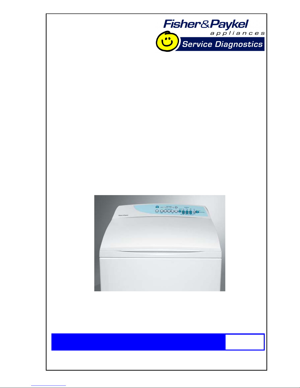
Data Display
To enter the DATA DISPLAY screens, push the LIFECYCLES button again
(SPECIAL button on Phase 5). This will enable the out of balance switch to
be tested, as well as giving access to the Detailed Fault Codes and User
Warning Faults. One of three displays will appear in the screen. Use the
OPTIONS up or down buttons to the bottom of the display screen to toggle
between these displays (use the buttons to the right of the display on Phase
5).
The Warning Status screen will
display the last USER WARNING
FAULT that occurred and will show
at what part of the cycle it occurred.
The User Warning Faults are as
follows:
• No Taps
• Overloaded
• Out Of Balance
• Over Suds or water still in the
SmartDrive during spin
• No Hot Water
• No Cold Water
• Agitate Overloaded
15
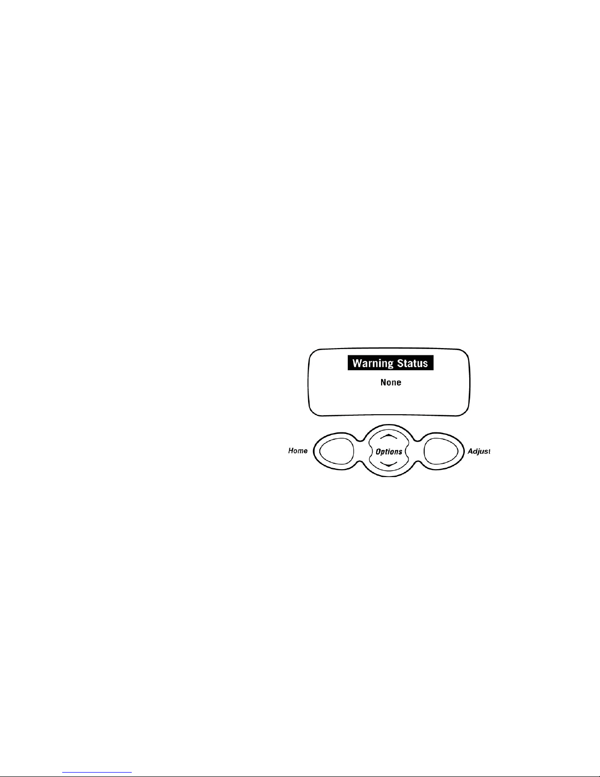
On Phase 5, the Machine Status
screen displays the thermistor
temperature and the status of the
out of balance switch and the lid
switch. It also displays the Size
setting of the SmartDrive and the
water level.
On Phase 6, the Machine Status
screen displays the status of the
diverter and the out of balance
switch. It also displays the Size
setting of the SmartDrive and the
thermistor temperature.
HVDC is for on line testing in the
factory.
Target temp is the temperature
selected.
T is the actual temp of the inlet
chamber water.
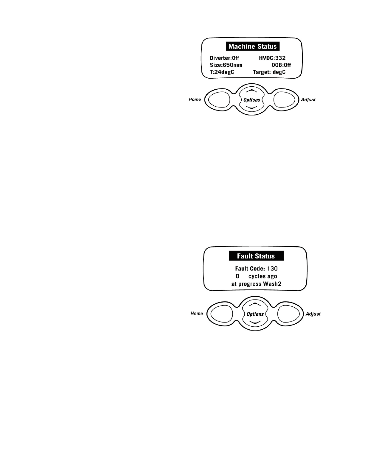
The Fault Status screen will display
a code for the last fault that has
occurred in the SmartDrive. It will
also display how many cycles ago
the fault occurred and at what part
of the cycle.
See Detailed Fault Codes for
servicing tips.
The fault code number can now be checked in the detail fault codes, to
ascertain what repairs may be necessary.
Lid Switch Test (Phase 5 Only)
Enter the Diagnostic Mode and bring up the Machine Status display.
Activating the lid switch by opening and closing the lid will change the display
between “Lid closed” and “Lid Open”.
 Loading...