

Page 1
C
L
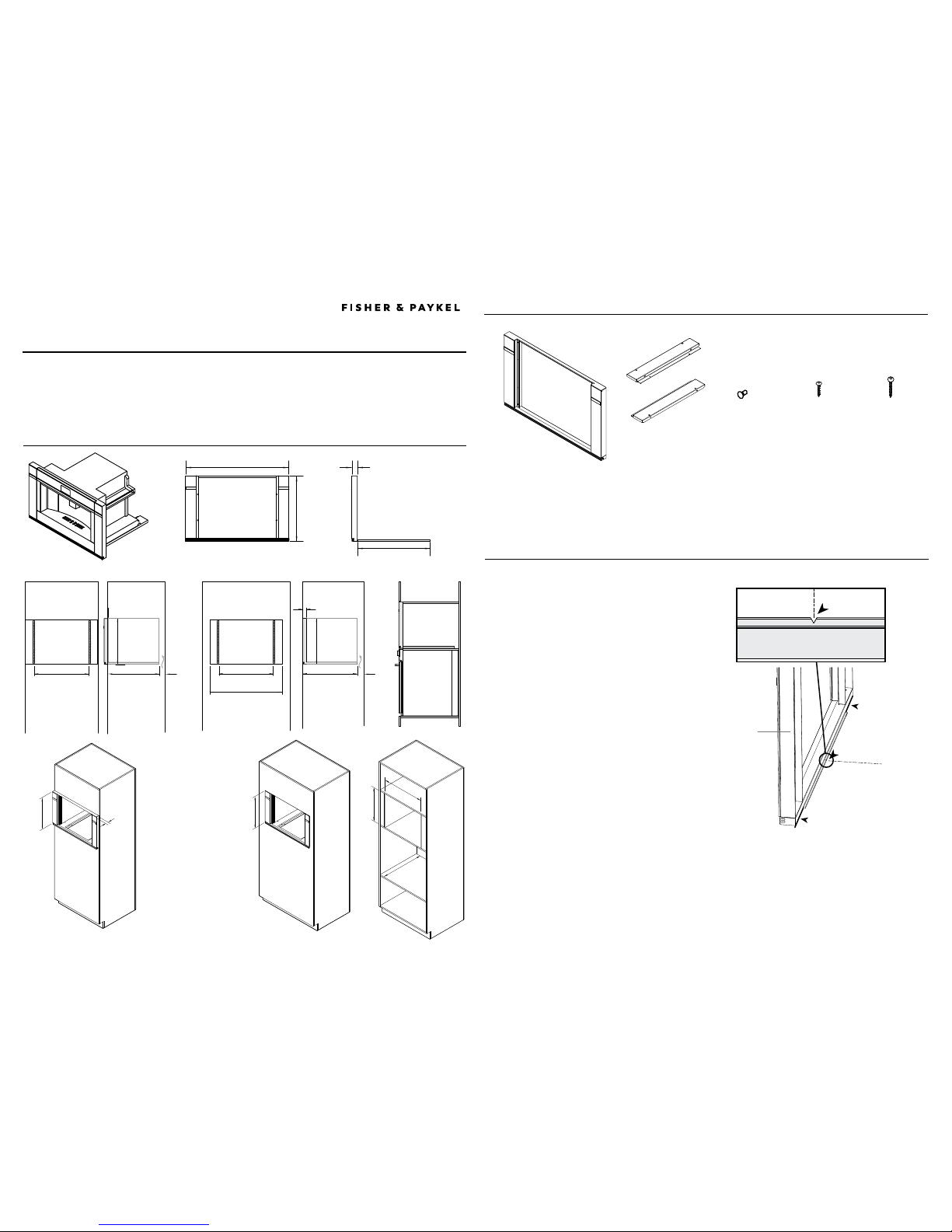
2 PARTS SUPPLIED
3 POSITION TRIM SURROUND ON CABINETRY
US CA
COMPANION COFFEE MAKER
ACCESSORY 0” TRIM KIT
INSTALLATION GUIDE
Center line mark
Center line mark
Front edge of cavity
Front edge of cavity
Trim Surround
Line up the cut “V” with your cavity center mark
IMPORTANT!
●
Ensure all packaging and protective film
is removed from the Trim Surround before
installing.
1 Mark the center of your cavity at the front.
2 Mount the Trim Surround with the small lip
resting flat on the front edge of the cabinetry
shelf.
3 Center the Trim Surround by lining up the
small cut “V” in the lip with your center mark
from Step 1.
Note: If installing Coffee Maker above an Oven,
ensure both products are centered and aligned
in the cabinetry.
Product Support
Brackets (2)
(for supporting your
companion product)
Trim Surround (1)
Phillips
1 3/4” (45mm)
screws (4)
(to secure the
Trim Surround)
Phillips
5⁄8” (16mm)
screws (8)
(to secure
the Product
Support
Brackets)
Rubber plugs (4)
(for plugging spare
Trim Surround
holes
continued >
Keep this document handy for easy reference.
●
This Trim Kit is designed to complement your companion product if installing into 30” wide cabinetry.
●
For contact information or if you require service, assistance or replacement parts, see the end of this document or your ‘Service &
warranty’ booklet.
This Trim Kit is designed to be installed ONLY with the FISHER & PAYKEL
- Companion Coffee Maker EB24DSX
- or in combination with OB30 Ovens
Trim Surround dimensions
1 5/8” (42mm)
min.
18 1/2”
(470mm)
18 7/8”
(480mm)
min. 22 1/16” (560mm)
min. 22 1/16” (560mm)
FLUSH (INSET) INSTALL
FLUSH (INSET) INSTALL
FLUSH (INSET) INSTALL INSTALLATION
WITH OB30
INSTALLATION
WITH OB30
PROUD INSTALL
PROUD INSTALL
PROUD INSTALL
min. 22 1/16” (560mm)
1 5/8” (42mm)
min. 29 15/16” (761mm)
29 13/16” (757mm)
18 13/16”
(478mm)
20 7/8” (530mm)
Cutout to allow
for Ventilation
1 15/16” (50mm)
Refer to separate
Product Install
Guide
Refer to separate
Product Install
Guide
Cutout to allow
for Ventilation
1 15/16” (50mm)
min. 22 1/2” (572mm)
1 5/8” (42mm)
18 13/16”
(478mm)
18 7/8”
(480mm)
18 1/2”
(470mm)
Proud = 22 5/8” (575)
Flush = 24 3/16” (614)
A dividing shelf
is required
22 1/16” (560mm)
*
**
**
**
*
Cavity side walls must be
strong and structurally
supportive
●
to secure Trim Surround
●
to secure oven to
Note: Cavity Depth is
dependant on products used.
1 CABINETRY SPECIFICATION
Page 2
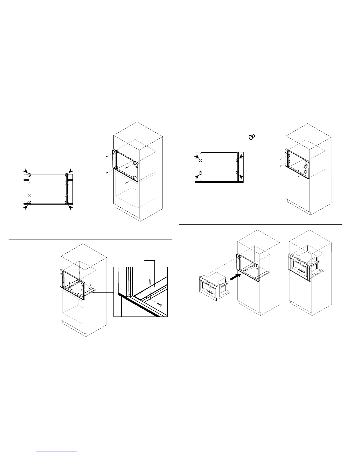
4 SCREW THE TRIM SURROUND ONTO THE CABINETRY
Secure the Trim Surround using the
screw hole locations shown
Using the 4 supplied screws, secure the Trim
Surround to the cabinetry in the correct hole
positions, as shown.
Pre-drill as necessary to avoid splitting the
wood.
IMPORTANT!
Do not screw through either center holes in
the Trim Surround.
5 SECURE THE TWO SUPPORT BRACKETS IN THE CAVITY
1 Position left and right support
brackets as shown inside, against
the walls of the cavity.
We recommend butting the
brackets up against the rear
frame of the Trim Surround.
2 Secure through front and rear
hole locations on both brackets
using the screws supplied.
Support
Bracket
6 FIT THE FOUR RUBBER HOLE PLUGS
Fit the 4 supplied rubber plugs into the Trim
Surround in the correct hole positions, as
shown.
x4
7 INSTALL YOUR COFFEE MAKER (REFER TO SEPARATE INSTRUCTIONS SUPPLIED WITH COFFEE MAKER)
1 Install your Coffee Maker as per it’s installation
instructions. Ensure the slides are secured correctly
2 Position your Coffee Maker in the cavity. Ensure the
Coffee Maker and Trim Kit are correctly aligned and
the Coffee Maker can open and close freely, before
securing.
591534A 12.17
 Loading...