

Fisher & Paykel DD603-88269, DD603-88270, DD603-88445, DD603-88445-B, DS603-88272 Installation Guide
...Page 1
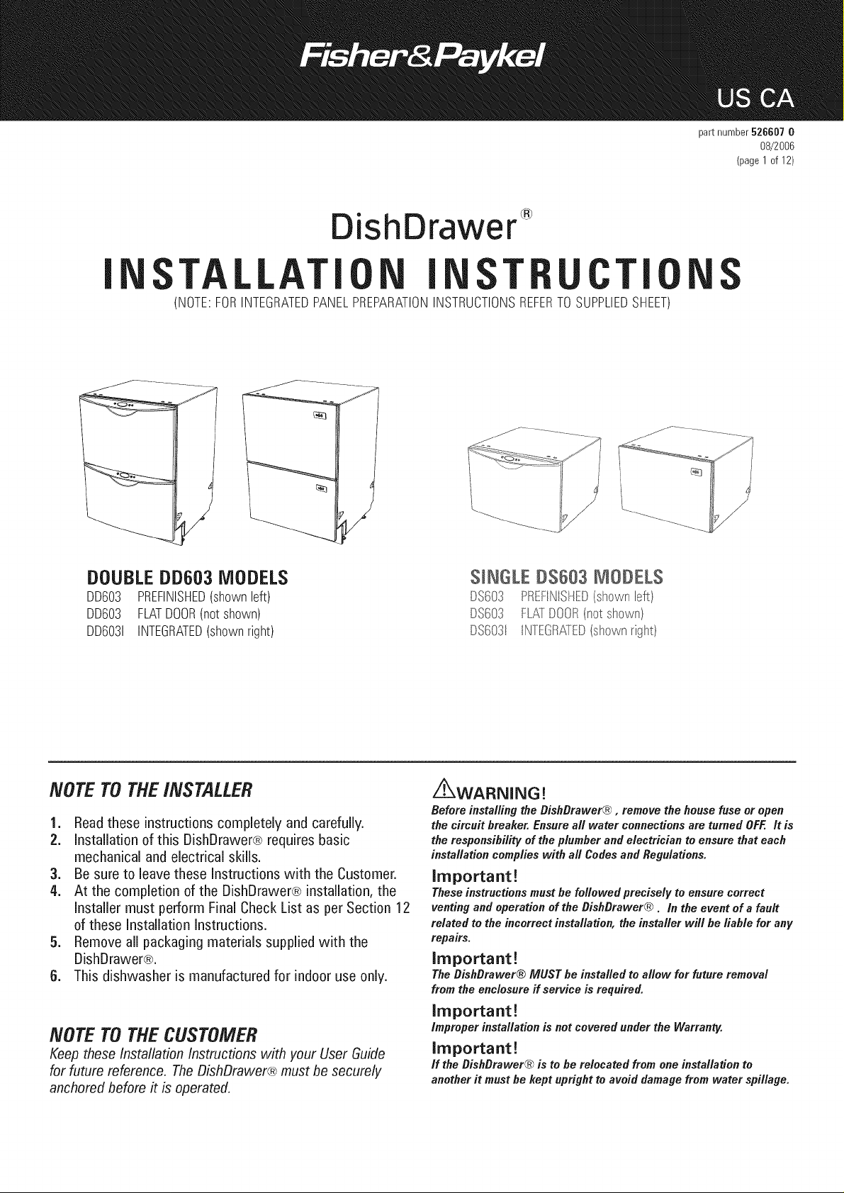
ishDrawer
part number526607 0
08/2006
(page1of 12)
®
I
TALLATI I T U TI
(NOTE:FORINTEGRATEDPANELPREPARATIONINSTRUCTIONSREFERTOSUPPLIEDSHEET)
DOUBLEDD603 MODELS
DD603 PREFINISHED(shownleft)
DD603 FLATDOOR(notshown)
DD6031 INTEGRATED(shownright)
SINGLE DS683 MODELS
DS603 PREFINISHED(shownbft}
DS603 FL£ DOOR(not shown}
DS6031 INTEGR£ED(shownright}
NOTE TOTHEiNSTALLER
1. Read these instructions completely and carefully.
2. installation of this DishDrawer® requires basic
mechanical and electrical skills.
3. Be sure to leave these instructions with the Customer.
4. At the completion of the DishDrawer® installation, the
installer must perform Final Check List as per Section 12
of these installation instructions.
5. Remove all packaging materials supplied with the
DishDrawer®.
6. This dishwasher is manufactured for indoor use only.
NOTE TOTHECUSTOMER
Keep these Installation Instructions with your User Guide
for future reference. The DishDrawer® must be securely
anchored before # is operated.
Z_WARNING!
Before installing the BishBrawer@ , remove the house fuse or open
the circuitbreaker. Ensureall water connectionsare turned OFF.It is
the responsibilityof the plumber andelectrician to ensure thateach
installationcomplieswith all CodesandRegulations.
Important!
These instructions must be followed precisely to ensure correct
venting and operation of the BishBrawer® . In the event of a fault
related to the incorrect installation, the installer will be liable for any
repairs.
important!
The BishBrawer® MUST be installed to allow for future removal
from the enclosure ff service is required.
important!
improperinstallationis not covered under the Warranty.
Important!
if the BishBrawer® is to berelocated from one installation to
another it must be kept upright to avoid damage from water spillage.
Page 2
._.BEFORE YOU START- DOUBLE S#NGLE MODELS
DishDrawer
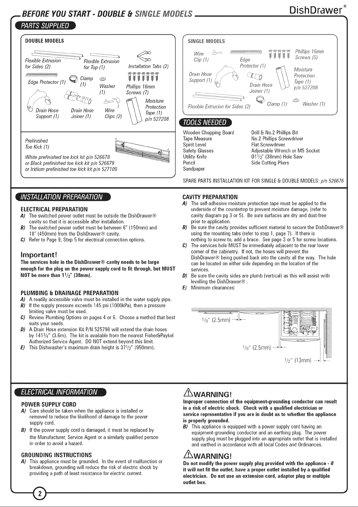
DOUBLEMODELS
FlexibleExtrusion ........ FlexibleExtrusion
for Sides(2) for Top(1)
EdgeProtector (1) @ Clamp @
(1) Washer
(1)
DrainHose DrainHose Wire
Support (1) Joiner (1) Clips(2)
ToeKick (1)
Prefinished
Whiteprefinished toe kickkit p/n 526678
or Blackprefinished toekick kit p/n 526679
or Iridium prefinishedtoekick kit p/n 527109
ELECTRICAL PREPARATION
A) Theswitched power outlet must beoutsidethe DishDrawer®
cavity so that it is accessibleafter installation.
B) Theswitched poweroutlet must bebetween6" (150mm) and
18"(450mm) from the DishDrawer®cavity.
C) Referto Page9, Step5 for electricalconnectionoptions.
Installation Tabs(2)
Phillips 16ram
Screws (7)
Moisture
Protection
Tape(1)
p/n 527208
Important!
The services hole inthe DishDrawer® cavityneedsto be large
enoughfor the plugon the power supply cordto fit through, but MUST
NOTbe more than 11/z" (38ram).
PLUMBING 8 DRAINAGE PREPARATION
,4) A readily accessiblevalvemust be installed in the water supply pipe.
B) If the supply pressureexceeds145psi (1000kPa),thena pressure
limiting valve must be used.
C) Review PlumbingOptionson pages4 or 6. Choosea methodthat best
suitsyour needs.
B) A DrainHoseextensionKitP/N 525798will extendthe drain hoses
by 1413/4"(3.6m). Thekit is availablefrom the nearestFisherSPaykel
AuthorizedServiceAgent. DONOTextend beyondthis limit.
E) This Dishwasher'smaximum drainheightis 371/2'' (950mm).
SINGLEMODELS
Ph%t?s16ram
Screws(5)
DrainHose
Support(1) _./
Ftexib/eExtrusionfor Sk:/es(2)
WoodenChoppingBoard
TapeMeasure
Spirit Level
Safety Glasses
Utility Knife
Pencil
Sandpaper
SPAREPARTSINSTALLATIONKITFORSINGLE8 DOUBLEMODELS:p/n526676
CAVITY PREPARATION
A) Theself-adhesivemoisture protectiontape must be appliedto the
undersideofthe countertopto prevent moisture damage,(referto
cavity diagrampg 3 or 5). Besuresurfaces aredry and dust-free
priorto application.
B) Besure the cavity provides sufficient materialto securethe DishDrawer®
usingthemountingtabs (referto step 1,page7). Ifthere is
nothingto screw to, add a brace. Seepage3 or 5for screw locations.
C) The serviceshole MUSTbeimmediately adjacentto the rearlower
cornerofthe cabinetry. If not, the hoseswill preventthe
DishDrawer®beingpushedback intothe cavity allthe way. Thehole
canbe locatedon eitherside dependingonthe location ofthe
services.
B) Besure the cavity sides areplumb (vertical) asthis will assist with
levellingthe DishDrawer®.
E) Minimum clearances:
/ /
'<_'J DrainHose
Joiner (1)
_ Clamp(1)
Drill8 No.2 PhillipsBit
No.2 PhillipsScrewdriver
FlatScrewdriver
AdjustableWrench or M5 Socket
O11/2"(38mm)HoleSaw
SideCuttingPliers
Moisture
Protection
Ta-pe_'1,_
p/n 527208
C_
[,¢'#sher(1)
POWER SUPPLY CORD
A) Careshouldbetaken when the applianceis installedor
removedto reducethe likelihoodof damageto the power
supply cord.
B) If the power supply cordis damaged,it must be replacedby
the Manufacturer,ServiceAgent or asimilarly qualified person
in orderto avoida hazard.
GROUNDING INSTRUCTIONS
A) This appliancemust be grounded. In the event of malfunction or
breakdown,groundingwill reducethe risk of electric shockby
providinga path of leastresistancefor electric current.
/_WARNING!
Improper connectionof the equipment-groundingconductorcanresult
in a risk of electricshock. Check with a qualified electrician or
service representativeif you are in doubt as to whether the appliance
is properlygrounded.
B) This applianceis equippedwith a power supply cordhaving an
equipment-groundingconductorandan earthingplug. Thepower
supply plug mustbe plugged intoan appropriateoutletthat is installed
andearthedin accordancewith all localCodesand Ordinances.
z_WARNING!
Donot modify the power supplyplugprovidedwith the appliance - if
it wiJJnotfit the outlet, have a properoutletinstalled by a qualified
electrician. Donotuse an extension cord,adaptor plugor multiple
outlet box.
Page 3
,.. DOUBLEMODELS
DishDrawer
5/16" k --.
WATER CONNECTION
RecommendedHOT
(Maximum 140°F/60°0).
Suppliedhoseto suit 3/8"(gmm)
malecompressionfitting.
WATER SOFTENER MODELS
Referto your DishDrawer® UserGuidefor
how to set upyour water softener.
WATER PRESSURE Maximum Minimum
WaterSoftener Models 145p.s.i.(1000kPa) 14.5 p.s.i. (100kPa)
OtherModels 145p.s.i.(1000kPa) 4.3p.s.i. (30kPa)
BRAIN CONNECTION
DrainHoseJoiner to suitO3/4'' +_5/64",O5/8'' +_5/64" and
O1" +_5/84"waste tees.
ELECTRICALCONNECTION
110-120VACpoweroutlet,9 AmpsMinimum.
LENGTH OF SERVICES (FROMPRODUCTEXITPOINT)
Drainhose- 889/16" (2250mm)
Inlet hose- 687/8" (1750mm)
Powersupply cord- 44" (1125mm)
NOTE:Servicesapproximatelyexit product 77/16'' (189mm)from left;
215/8'' (550mm)from front; 311/4'' (793mm) from top.
/Smm) |
_ " _/ | I (2rnm)
_'_o_ [ |l Tab
227/16"
I_ (57°L_m)
#
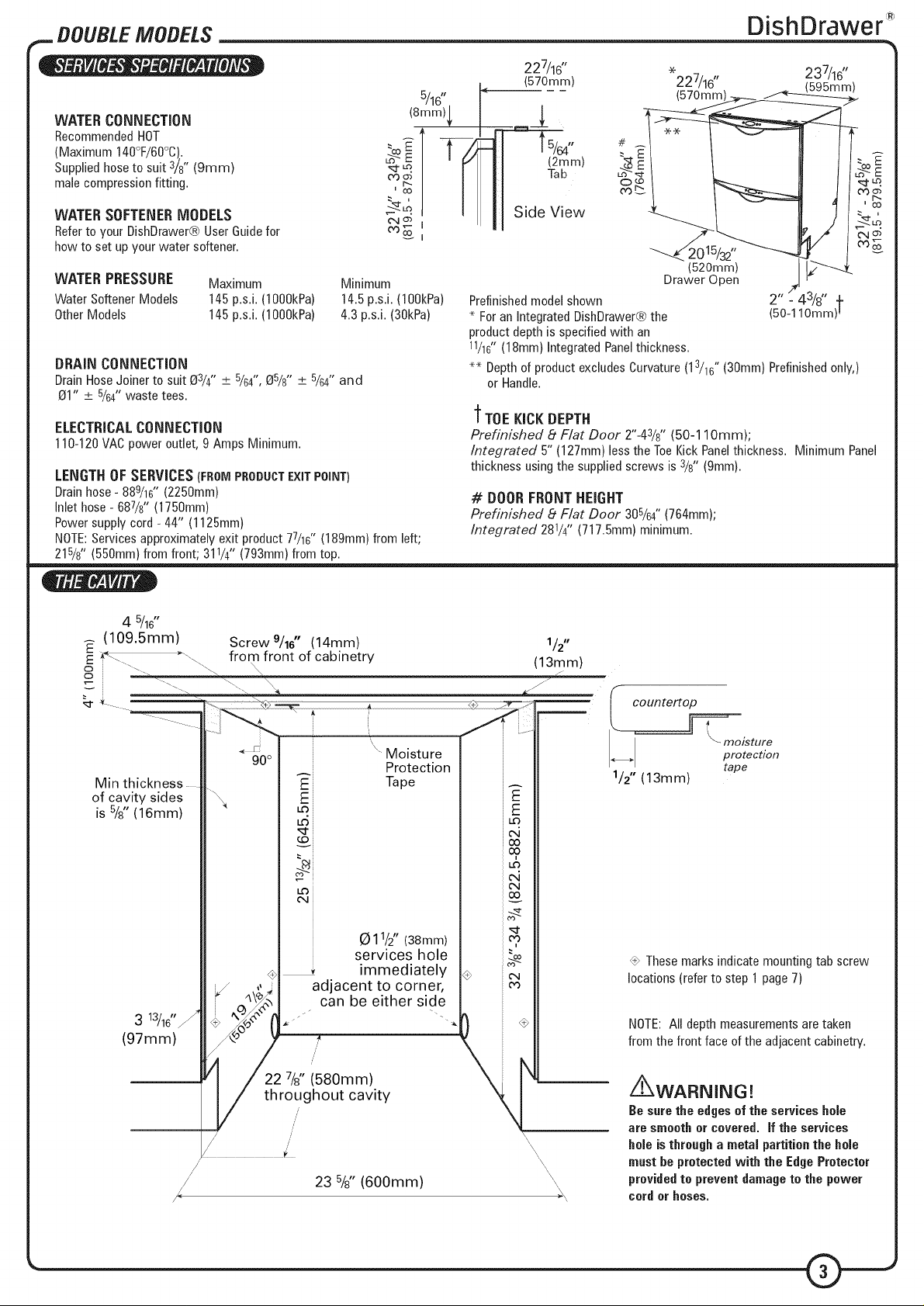
Prefinished model shown 2" - 43/8" +
* For an Integrated DishDrawer® the (50-1 lOmm) !
product depth is specified with an
11/16"(18mm} Integrated Panel thickness.
** Depth of product excludes Curvature (13/18" (30mm} Prefinished only,}
or Handle.
%
227/16"
{578mm)
(520mm)
Drawer Open
237/16"
(595mm)
"_TOE KICK DEPTH
Prefinished 8 F/at Door 2"-43/8" (50-1 lOmm);
/ntegrated 5" (127mm)less the ToeKick Panelthickness. Minimum Panel
thicknessusingthe suppliedscrews is 3/8"(gmm).
# BOOR FRONT HEIGHT
Prefinished 8 F/at Door 305/64"(764mm);
/ntegrated 281/4'' (717.5mm)minimum.
4 5/16"
(109.5mm!,
Min thickness
of cavity sides
is 5/8"(16mm)
Screw 9/16" (14mm) 1/2"
from front of cabinetry (13m m)
• z
f
,,<............ _ _....... _" [ countert
.................................... _\ [i _ ....................... _ l °_r=,_
< _ " Moisture n
90° Protection tape
A_
E Tape
LO::
r.D_
C_4_
0 11/2"(38mm)
services hole
÷ _ immediately
,, j adjacent to corner,
A
t._
m,
E
E
1/2" (13mm)
Thesemarksindicatemountingtab screw
locations(referto step 1 page7)
_, can be either side
NOTE:All depth measurementsare taken
from the front face ofthe adjacentcabinetry.
/ 22r7/{' (580mm) X \t oughout cavity
23 %" (600mm)
i_WARNING!
Be surethe edges of the services hole
are smooth or covered. If the services
holeis through a metal partitionthe hole
must beprotectedwith the EdgeProtector
providedto preventdamagete the power
cordor hoses.
Page 4
DOUBLEMODELS
DishDrawer
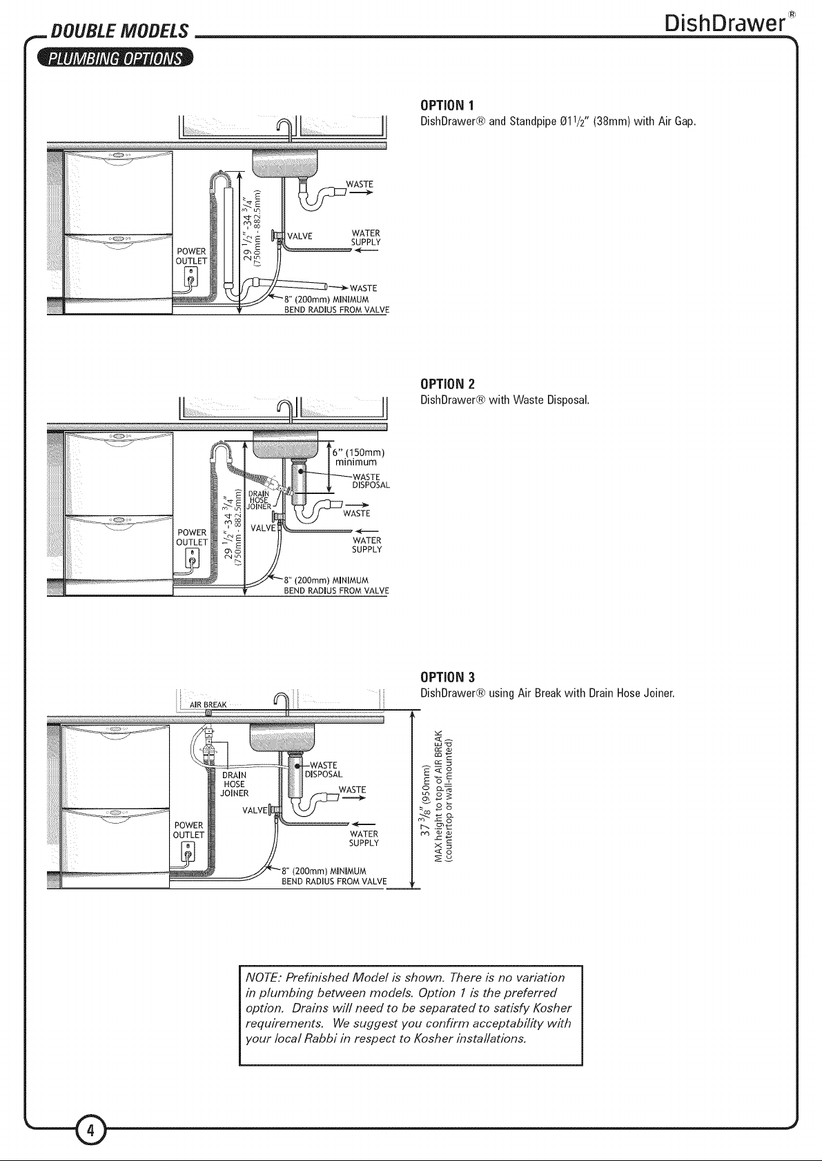
OPTION1
DishDrawer®andStandpipeO11/2"(38mm)with AirGap.
VALVE WATER
_ _--"_'- WASTE
(2O0mm) MINIMUM
BEND RADIUS FROM VALVE
BEND RADIUS FROM VALVL
SUPPLY
OPTION2
DishDrawer®withWasteDisposal.
OPTION3
DishDrawer®usingAirBreakwith DrainHoseJoiner.
cz= o_
DISPOSAL
WASTE
WATER
SUPPLY
(2O0mm) MINIMUM
BEND RADIUS FROM VALVE
NOTE." Prefinished Mode/is shown. There is no variation
in plumbing between mode/s. Option 1 is the preferred
option. Drains wi// need to be separated to satisfy Kosher
requirements. We suggest you confirm acceptabi/ity with
your/oca/Rabbi in respect to Kosher insta//ations.
E<o
E'_z
c_O_
r=8-
r-_ ._
©
Page 5

SINGLE MODELS
DishDrawer
(570ram)
(8mm)
WATER CONNECTION
RecommendedHOT
(Maximum 140"F/60°C)_
SuppBiedhoseto suit 3}s"{9mm) male
compressionfitting_
WATER SOFTENER MODELS
Referto ,four DishDrawer_ UserGuide
for howto set up,four water soffener_
WATER PRESSURE Maxim_,_m Mhsimum
WaterSoftener Models 145p_sJ_(10OOkPa) 14_5FsJ. (10OkPa)
OtherModels 145p.sJ.(1000kPa) 4.3p.sJ. (30kPa)
#RA_N CONNECTION
DrainHoseJoiner to suit 8s/4" ::.+.:5/64" and85}s'' ::.+.:5/G4"waste tees.
ELECTRICALCONNECTION
110_120VACpoweroutle%4_5AmpsMinimum_
WEIGHT
Full93 Ib(42kg) Prefinished
Empty62 [b (28kg} Prdinished
....... (570ram)
Side View
(4Ogmm)
Refinished model shown
_For an Integrated DishDrawer_ the producL depth is specified with an
11/16"(18ram} Integrated Panel thickness_
_ Depth of product excludes Curvature (13/1G" (30ram} o
prefinished onlv}, or Handle.
LENGTH OF SERVICES (FROMPRODUCTEXITPOH_T)
Drainhose_889/1G'' (2250mm)
hlet hose_ 68%" (1750mm}
Powersupplv cord _44" (1125mm}
NOTE:Servicesapproximatelvexit product 77/1G'' (189mm}from left;
215/s'' (550ram)from front; 15_/f' (393mm)from toF
O - •
v
%
(97mm)
Moisture
Protection Tape
Q11/2" (38mm) services
hole immediately
adjacent to corner,
/'_can be either side
227/8" {580ram)
/ throughout cavity
235/8" (600mm)
(13mm)
/
J , "- FFIO/$rUFe
i. _ protection
1/2" (13mm)
tape
Minimum
thickness of
_mportant!
Adjacent cabinetrV must
not extend above
cavity base,
These marks indicate mounLing
tab screw locations
(refer to step 1 page 7)
NOTE: All depth measurements are taken
from the front face of the adjacent cabineLry.
NOTE: To align drawer front to adiacent
cabinetry, the producL to countertop
clearance can be increased from l}s" (3ram}.
Be sure the e_ges of the services bole
are smooth or coyote& [f the services
bo_eis through a metal #artitio# the
bo_em_st be £roteote_ with the E_ge
Protector £rovi_e_ to £reve_t _ama#e to
the #ower cor_ or hoses.
Page 6

SIN#LE MODELS
WASTE
WASTE
(200ram/MNi,,'_U M
BEND RADIUS FROM VALVE
11
DishDrawer
OPTION1
DbhDrawer@andStandpipe811/2"(38ram)withAirGap.
OPTION 2
DishDrawer@with Waste Disposal.
BREAK
_6" !150mm}
mm[mum
DISPOSAL
WATER
SUPPLY
OPTION 3
DBshDrawer@usinfj Air Breakwith Drain HoseJoiner.
tY_ o_ o_
BEND RADIUS FROM VALVE
NOTE: Pre£,;_/shed Model ,@shown. X4ere ,@no var/at,;on
,@p/umb,@g between models. Option 1is t,4epreferred
opt,;on. Dra/'ns _;/'f need to be separated to sat,@fyKosher
requbements. _4/_,sudgest you con_{;rm acceptab,;//ty with
your local Rabbi ,;n respect to Kosher ,;nstaL/ationso
Page 7

_ iNSTALLATiONiNSTRUCTiONS
PLEASE NOTE: Yourmodelof DishDrawer®may differfrom the modelshown in the installation
diagrams,Installationis similarfor all modelsforeither Singleor Doublemodels,hformation re_erring
to Singlemodelsonly is highlightedir_blue,installation diagrams have beensimplifiedto enaNe
clearerinstruction. FORiNTEGRATEDPRODUCTSFOLLOWTHEiNTEGRATEDPANELPREPARATION
iNSTRUCTiONSP/N 526608,BEFOREMOVINGTHEPRODUCTiNTOTHECAVITY.
STEP1: MOVING THEPRODUCTINTOTHECAVITY
MOUNTING TAB OPTIONS
Themountingtabs are inpairs, oneon eachside of the product.Theyare
usedto securethe productto the cavity sides,installation requirestwo
sets of tab pairs be used. DOUBLEMODELSONLY- Q and_) tab pairs
OR_ and _ tab pairs may be used. All tabs would beoptimum.
ifthe top installationtabs _ areto be used,fit to the chassisby
O
inserting into the top slotsas shown. Ensurethe tabs arefully
lockedin place.
Optional Flexible Extrusion
g
ifthe cavity is 24"x 341/2"(610mm x 876mm)flexible extrusions
can beattachedalong the top andsides of the product. Openthe
drawer(s)to exposethe chassistrim. Removeextrusionbacking
andadhereto the sideandtop of DishDrawer®. Referto the
drawing for correctplacement.
Be surethat extrusions do not preventthe drawer from closing
completely.
DishDrawe¢
READTHESEiNSTRUCTiONS
COMPLETELYANDCAREFULLY.
_WARNING!
Be careful of
sharpedges.
Important!
DONOTpush
middle of drawer(s).
STEP2: REMOVINGTHETUB
O Check for obstructionsthat interferewith
cavity any may sliding
the product back. DOUBLEMODELSONLY- loosenthe feet first.
O Pushproductinto cavityto suit adjacent cabinetry. Do not push
middleof drawer(s). Be sure inlet, drainhose(s)and power supply
cordare not restricted or damagedby carefully pullingall excess
lengththroughthe serviceshole,while the product is being pushed
back intothe cavity.
FORSINGLE MODELS, check that the base of the prod_,Jc[is not
howe& Do not rest single models on your knee when moving them
into the cavity.
Important! (SmNGLEMO#ELSO[_L¥/,
The preduct may mere, Mark chassis pesitieH eu cavity,
g SINGLEMODELSONLYtGently openthe drawer and mark[he
chassispositionon the cavity, beforeremovingthe tub.
Openthe drawer (bottom drawerin DOUBLEMODELS).Release
the tub bydepressingthe right handtub clip and pushingit back
13/16" (30mm). Repeatonthe lefthandside.
4,
g Lift the tub up off the drawer runners.
Q Slide both runnersbackinto the product.
Q Place the tub onto the floor.
For SINGLE MODELS, depending on the height of the cavity, the tub
will need to be supported, eg on a chair.
Page 8

._ INSTALLATION INSTRUCTIONS
STEP3: ADJUSTINGTHEFEET(DOUBLEMODELSONLY)
DishDrawe¢
DOUBLE MODELS ONLY
Adjust the heightofthe productto suitthe cabinetry,by turning the
feetfrom inside the product usingawrench or M5 socket.
TIP - gently take the load off each foot using the slide and
then turn by hand.
NOTE." For integrated products, the upper pane/may be
a/igned with the top of the adjacent cabinetry, provided
a minimum 3/16" (5mm)c/earance from the counter is
maintained.
Important!
The productmust be levelled to within 3/32" (2.Smm)from front to
back, and side to side.
Important!
The productshould NOTsupport any part of the kitchen cabinetry.
TIP- Place a spirit level on the drawer runners to level the
product.
STEP4: SECURINGTHEPRODUCT
_]_ SINGLE MODELS ONLY
Checkthe position ofthe chassisis still where marked onthe cavity,
beforesecuringthe product.
Therearefour 5/8"(16mm)roundholes,two onthe left andtwo
the right handside in the sound insulation. Theseprovideaccessto
the mountingtabs.
Tosecurethe product to the cabinetry usea 5/8"(16mm)
Phillipsscrew ineach mountingtab.
Makesure the sound insulationis positionedcorrectlybefore
continuinginstallation.
_ DOUBLE MODELS ONLY
Screw the two top tabs to the undersideof bench. Usethe supplied
Phillips5/8" (16mm) screws. Tabscanaccommodatea maximum of
3/4"(19mm)vertical gap.
on
Page 9

_. iNSTALLATiONiNSTRUCTiONS
STEP5: ELECTRICALCONNECTION
DishDrawer
POWER
OUTLET
Thisview shows the bottom left-handrearcornerwith the cover removed
_WARNING!
The productMUST NOTbe
pluggedin at this stage.
_Be surethereis a power outletin reachof the suppliedpower cord.
ifthere is not a suitable outletavailablethen haveoneinstalled by a
qualifiedelectrician.
Do not use an extensioncord.
_ Alternatively,the DishDrawer® be permanentlyconnectedto amay
flexible conduit.
Removethe power supply cord. Removeroundknock-outfor cable
clamp. Fitsuitablecable clampfor the conduitandterminate the
wiring as shown. Terminatethe groundwire usingthe saddlethat
was usedonthe existing earth.
i_WARNING!
If permanentlyconnectingbe
sure the power isisolated.
Z_WARNING!
Thismust only be donebya certified person.
STEP6: REFITTING THE TUB
TUB CLIR _
Important!
Before refitting the tub, he sure the hosesare not twisted and the
latches at the rear of each drawer runner are facing forward.
_To refitthe make both of the latches the ofeach
drawerrunnerarefacing forward. Ensurehoses are hooping
upward. Placethe tub onthe half opendrawer runnersandclose
the drawer.
_ Checkthetub clips have reseton both sides of the tub. If not, pull
the tub clipsforward until the tub clip button is reset.
tub, sure at rear
Important!
Besure the tub clipson both sides are reset.
Page 10

._ iNSTALLATiONiNSTRUCTiONS
STEP7: CONNECTINGTHEDRAIN HOSE(S)
DRAIN
HOSE
q[-VENT
WATER
SUPPLY
DishDrawe¢
DishDrawer®with HoseJoiner(see PlumbingOptions).
Remember to slip the wire clip(s) on the drain hose(s) first,
Slipa wire clip overeach drainhose,then pushthe hoses into
the DrainHoseJoiner firmly, 5 clicks. Positionthewire clip(s)
betweenthetwo positioning ribs onthe DrainHoseJoiner.
Attach the DrainHoseJoiner to the waste tee (see Plumbing
Options).Ensurea snugfit. Ifrequireda hose clamp may beused.
WASTE
n
When using the standpipeoption (see PlumbingOptions),hose(s)
shouldnot extendfurtherthan 43/4'' (120mm) downthe standpipe,
in orderto prevent siphoning.
Attach the DrainHoseSupportto the cabinetry(with the screw
supplied)to preventsiphoningandto keepthe drain hose(s)
from kinking. If required,the DrainHose(s)may betrimmed to a
suitablelength.
STANDPIPE
(see Plumbin9
Options 1 or 2)
STEP8: CONNECTINGTHEINLETHOSE
Important?
Minimum holesize to be connectedto the waste tee is 1/z"
(12.7mm).
Be sure the DrainHose(s)are fully extended te preventsagging
(see diagramte the left).
The DrainHosesupport must be used.
DrainHosejoinermust not support weight of hoses. Keep
excess lengthef Drain Hoseen the DishDrawer® side ef the
DrainHosesupport or trim te suit.
i_WARNING?
DONOTplugthe productin
at this stage.
_ Connectthe Inlet Hoseto the water supply. Be surethe sealing
washer is in place. Thehose couplingmust betightened a further
halfturn after seal contact.
Important?
DONOTcut the inlet hose.
TIP - Turn the water valve ON to check for any leaks,
Alternatively flexible stainless steel hose can be plumbed directly to
the inlet valve using a 3/8" brass adaptor (p/n 526161) available from
the nearest Fisher 8 Paykel Authorized Service Agent.
NOTE," SINGLE MODELS DO NOT HA VE A TOE KICK _0
INSTALL PROCEED _0 STEP 12 F/NAL CHECK L/S_
Page 11

._ INSTALLATION INSTRUCTIONS
STEP9: MEASURINGTHETOEKICK(DOUBLEMODELS ONLY)
_ Partiallyopenthe bottomdrawer. Turn PrefinishedToeKick
/
/
|
DishDrawer
upsidedown and holdvertically againstthe bottom edgeof the
Tub side (not the drawer front).
Mark the position ofthe bottomedge of the Tubsideonthe ToeKick.
Choosethe nearestgrooveto the pencilmarkwhich will result
in the shortestToeKick.
STEP
10:
TRIMMING THETOEKICK (DOUBLEMODELS ONLY)
©
Important!
Before cutting ensurethe Toe Kickis positionedon a wooden
choppingboardto avoid damageto surrounding area.
_On the chosen groovecut downthe vertical ribs at the centreand
the endsusing a knife. Cut alongfull lengthwith a knife.TurnToe
Kick over,bendand then cut from front. Sandor scrapebottom edge
to remove rough patches.
Z_WARNING!
Remove all sharp edges
_To avoida cutting hazardremoveall sharpedgesafter trimming.
_ RemoveToeKicktabs bysnappingthem off.
Page 12

_. iNSTALLATiONiNSTRUCTiONS
STEP11 FITTINGTHETOEKICKTOTHEPRODUCT(DOUBLEMODELS ONLY)
DishDrawer
Toekick
®
mountingrails
_ Partlyopenbottomdrawer. PositionToeKickbehinddoor and slide
ontothe mountingrails onthe undersideof tub.
_ Closebottom drawer, checkif flush with adjacentcabinetry.
If requiredopendrawer andadjust.
Note," C/earance between Toe Kick and floor must be
15/32" (12ram) minimum,
When ToeKick is in position, openbottom drawer and gentlyfasten
the ToeKickscrews, on eachside.
Important!
DONOTovertighten screws.
Overtighteningwill damagethe pJasticmounting detail.
STEP12: FINAL CHECKLIST (DOUBLE AND S/NGLE MODELS)
0
Besureproduct is level,securelyfastened to the cabinetry and
opensandclosesfreely. TheDishDrawer® must befree to close
with no resistancefrom the cabinetry.
0
Besurethe inlet hoseto valveconnectionis tightened a further half
turn after seal contact.
0
Besureany knock-outs or plugs indrain connectionhave been
drilledout and drainconnectionhasbeen made.
0
TurnONthe power andwater supply. The DishDrawer®should
beepand light up.
0
Openthe drawer(s)and check operationof Wash ProgramControl
Panelandcheckthe sprayarm(s)are in placeandfreeto rotate.
0
Onthe Wash ProgramControlPanelselect Rinseandclosethe
drawer(s). Startthe programby pressingthe Start!Pausebutton.
0
After the Rinseprogramhasfinished, besurethe machinehasrun
anddrainedcorrectly.
0
Checkwater supply anddrainageconnectionfor leakage.
0
Repeat for each Drawer.
0
LEAVE ALL LITERATURE WITH CUSTOMER,
STEP13: CUSTOMERCARE
TROUBLESHOOTING
0 Excessivewater remainingabovethe filter plate, after the
rinsecycle; checkfor kinkeddrainhosesor blockedwaste
connection.
0 No water supply;checkwater is connected,ONandthere is
the specifiedwater pressure.
0 DishDrawer® does not light up when the tub is opened;
be surepower is connectedand is switched ON.
0 Water aroundwater supply and drainageconnections-
check connections,existing plumbingand hosesfor leaks.
0 if a fault occurs, consultthe FaultCodeSectionofthe
UserGuide.
0 if unable to resolve, contact your Customer Care Centre.
if you haveany questionsconcerningthe installation of this DishDrawer®,
pleasecontact your Fisher8 PaykelAuthorizedServiceAgent.
FOR THE UNITED STATES OF AMERICA (USA) 8 CANADA
Fisher8 PaykelAppliances
5900 SkylabRoad
HuntingtonBeach
CA 92647
PHONE TOLL FREE 1888 9 F/VP USA
1888 9 367 872
wwwo usa° fisherpagkelo corn
 Loading...