

Page 1
Fisher&Poykel
DishDrawer TM
J
DS602 (Prefinished)
/ /
/
DS6021 (Integrated)
Part No. 525854/B Models DS602 DS602I
Page 2
NOTE TO THE INSTALLER
• Be sure to leave these instructions with the Customer.
• Ensure this appliance is properly grounded.
NOTE TO THE CONSUMER
• Keep these Installation Instructions with your Use & Care Manual for
future reference.
IMPORTANT
• Read these Instructions completely and carefully.
• Observe all governing Codes and Ordinances.
WARNING
• These Instructions are intended as a,guide _nly.
• It is the responsibility of the plumber and ele.ctrician to ensure that
each installation complies with all Codes and Ordinances.
• Installation of this D_shDrawer requires basic mechanical and
electrical skills.
• The installer is responsible for the DishDrawer installation.
Improper installation is not covered under the Express Warranty Form.
IMPORTANT
• At the completion of the DishDrawer installation, the Installer must
perform Final Checks as per Section 8 of these Installation
Instructions.
Page DS_01
Page 3

Section 1
1.1
1.2
1.3
1.4
1.5
1.6
General Information
Preparation
Product Specifications
Cavity Dimensions
Tools Needed to Install DishDrawer
Product Parts- Prefinished Single
Product Parts - Integrated Single
Section 2
Section 3
Section 4
Section 5
2.1
2.2
2.3
2.4
3.1
3.2
3.3
5.1
5.2
5.3
5.4
Electrical, Plumbing & Drainage Information
Electrical
Grounding Instructions
Plumbing - Water Supply
Plumbing - Drainage Options
Fitting the Single DishDrawer
Single DishDrawer Mounting Hole Locations
Connecting the Services f,
Flexible Extrusion Attachment for 24" Cavity
Inserting Single DishDrawer Into cavity
Information for Cabinet Maker for Integrated DishDrawer
Points to Consider ,
Integrated Overview
Integrated Drawer Front Dimensions
Shelf & Integrated Drawer Front Preparation
Section 6
Section 7
Section 8
6.1
6.2
6.3
6.4
6.5
8.1
8.2
Integrated Drawer Front Installation
Changing the Integrated Badge Enclosure
Disassembling the Integrated Badge Assembly
Assembling the Integrated Badge
Fitting the Badge, Handle & Mounting Panel to the Drawer Front
Fitting the Drawer Front to the DishDrawer
Final Fitting For Single DishDrawer
Final Checks
Installation Wet Test
Troubleshooting
Page DS 02
Page 4
WARNING
Before installing the
i )ishl "hawer. rem,-_\v lhe
GENERAL INFORMATION
Ensurethe DishDrawer enclosure is prepared for installation.
Remove all packaging and materials suppliedwith the DishDrawer.
It vim h,rve any (lueslinnscon(mnmg lhe inslallalion ol this Dishl)rawe_, _onna(:t
II_uit!_P',Ikol
I l_, r ,.! Wah_r
(:Ollllel.:liOllS are llJn'led
(91:1.
_ WARNING
The DishDrawer MUST
be installed to allow for
ll.mtre removal from lhe
elldOSUre it _'vice IS
mquired.
Fisher & Paykel Customer Care Centre
TOLL FREE 1-888-9-FNP USA
TOLL FREE 1-888-9-367 872
Fax (714) 829 8699
WWW.FISHERPAYKEL.COM
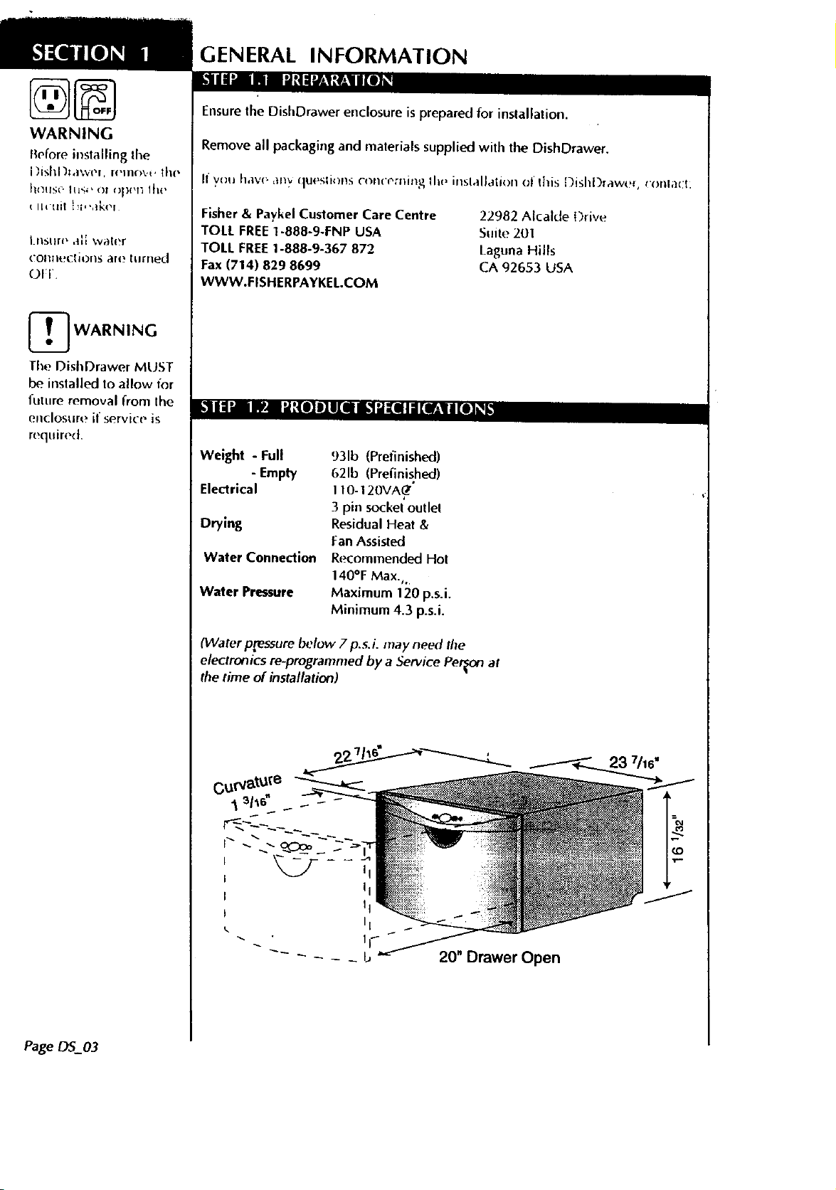
Weight - Full
- Empty
Electrical
Drying
Waler Connection
Water Pressure
931b (Prefinished)
621b (Pmfinished)
I t 0-120VA@"
3 pin sockel outlel
Residual Heat &
Fan Assisted
Recommended Hol
140°F Max.,.
Maximum 120 p.s.i.
Minimum 4.3 p.s.i.
22982 AlcaldeDrive
Suite 201
Laguna Hills
CA 92653 USA
Page 0S_03
(Water pressure below 7 p.s.i, may need fl_e
electronics re-programmed by a Service Person at
the time of installation)
I
I
I ii
II
II
II
-- - - - _ b 20" Drawer Open
Page 5
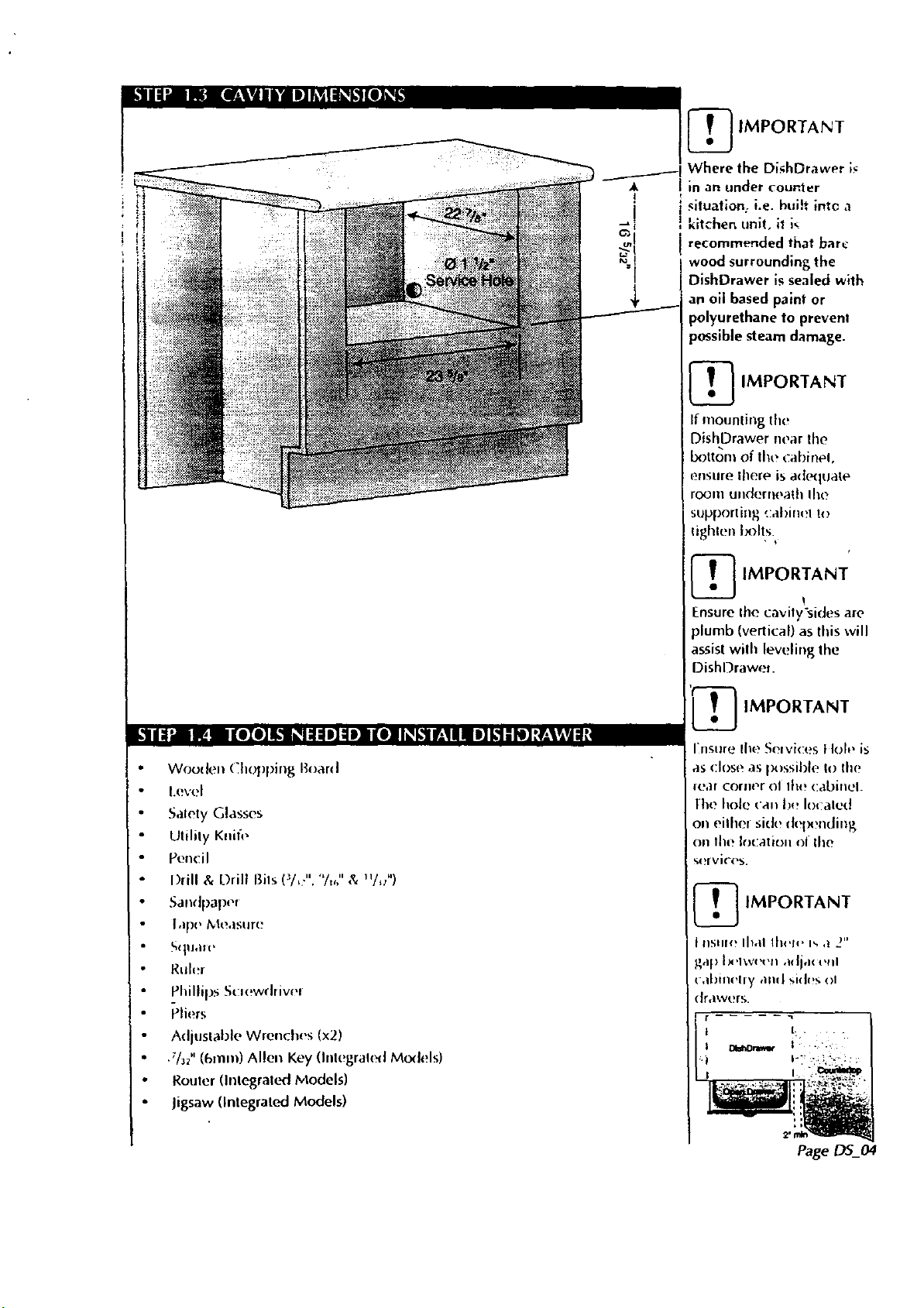
_ IMPORTANT
Where the DishDrawer _
Jin an under counter
i situat;on: i.e. huih into ,'!
I kitchen unit, 11i,
recommended that bare
wood surrounding the
DishDrawer is sealed with
an oil based paint or
polyurethane to prevenl
possible steam damage.
,_ IMPORTANT
[ If mounting the
DishDrawer near the
Ix)from of the cabinel,
(__nsure |here is ade(]tJaie
room ulld(:rllt_aihlile
supporting cabinet to
lighten l×_It,s.
_ IMPORTANT
_'III='-" :._! I[010]IL'I lglgll|]gl] ll[0] II+kII';IIII 'l]k1|ll]tl';VAVJll"
W®den Chr_pping I+oard
I+evel
Salety Glasses
Utilily Knife
Pencil
Drill & Drill Bits (_/+:","/.," & u/+/,)
Sandpapel
lape i_leasure
Squa.,
Ruler
Pldilips Scsewrilivel
Pliers
A(Ijuslal)le Wrenches (x2)
.7/3/' (6ram) Alien Key (Imegralc_l Models)
Router (Inlegrat(.n::lModels)
Jigsaw (Integrated Models)
Ensure the cavily"sides are
)lumb (vertical) as this will
assisl wilh leveling lhe
DishDraweL
_ IMPORTANT
Insure lhe Selvices IIt,h, is
as close as im_ssible 1o the
rear corne,r ol lhe (:abinel.
lhe hole ('all l)_! lo<aled
on eilhel side del_mding
on lhe It)cation of lhe
_ervices.
_ IMPORTANT
I IISIII<! lhal lh_,I(, I_ ,1 2"
gap Ix,Iw++t,n adja( t,lll
<al)inelry alld sides ol
drawers.
Page 6
1.
/
/
/
/
/
,_ _ _, \
00
8.
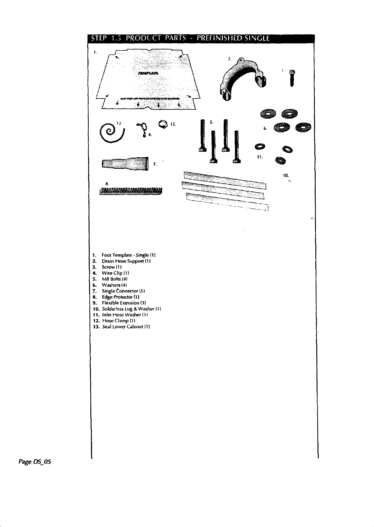
1. Foot Template -Single (1)
2. Drain Hose Supporl (1)
3, Screw (1)
4. Wire Clip (1)
S. M8 Boffs(4)
6. Washer_ (4)
7. Single Connector (t)
8. Edge protector(1)
9. Flexible Extrusion(3)
10. Soldertess Lug & Washer (1)
1T. Inlee Idose Washer (1)
12. Hose Clamp (1)
13. Seal Lower Cabinet (1)
10.
Page DS_05
Page 7
6, 5. 1
4.
_S. O
7.
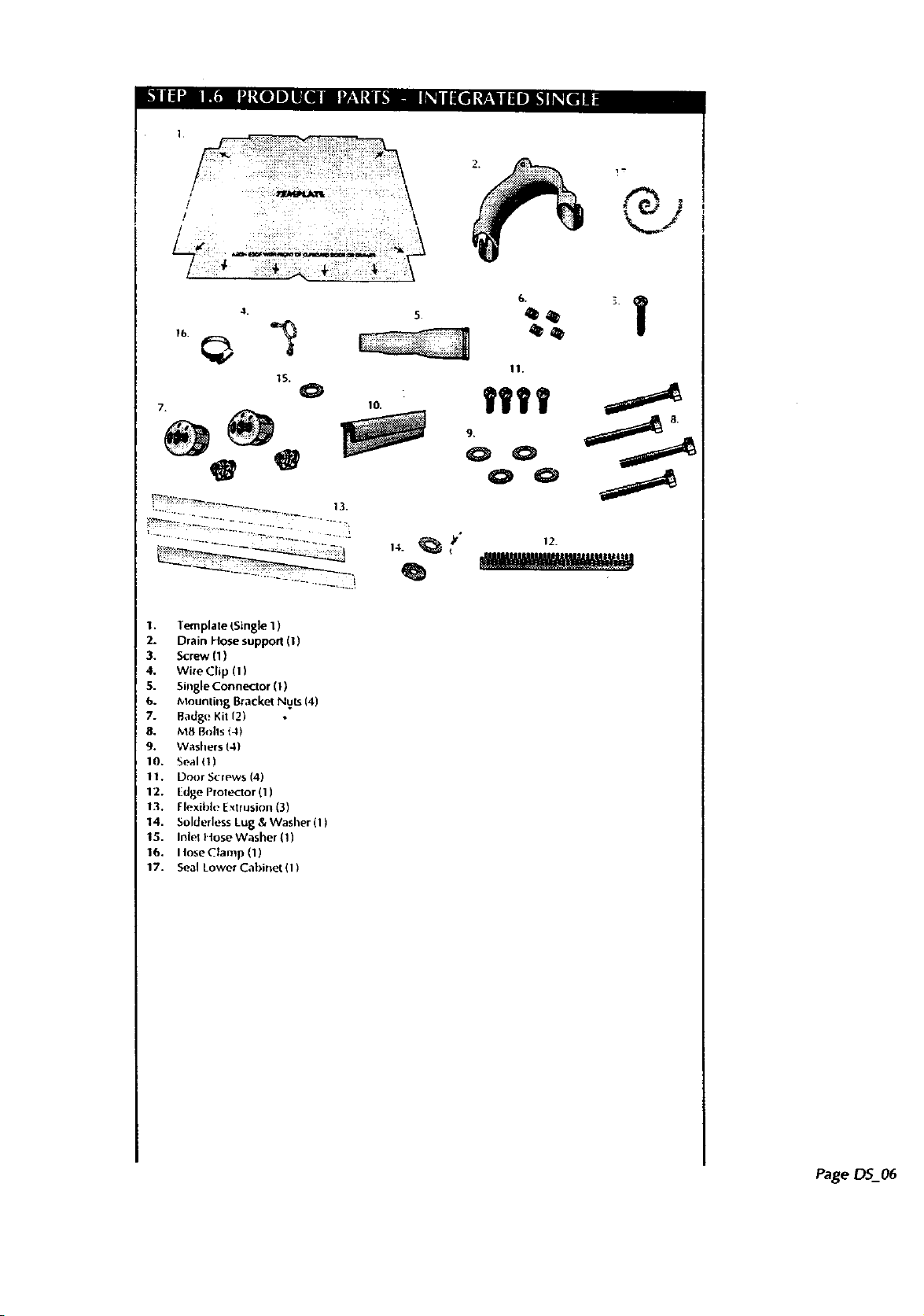
I. lemplate LSkn_ "l_
2. Drain _ose suppo_ {$)
3. Screw (I)
4. wi:e C_tip(.Ii
5. SingleConne_O_ (I)
_oUntil_ BTacke_Nuts _4)
b.
7- Bad_l_ Kit 12)
$. _B Bolts(-I_
9. Washers L4'_
10. Seal&1)
II, DoO(S_ews 14)
12, idle pioe_or (I)
lexbl* I'xu sio_ 3)
13. F " &Washer(l)
sold_._lesstu_
_4, i_|el _4ose .vXtashe_11_
15.
I_oseClan'_P(I)
16. Seal LoWe( Cabir_el tlY
17-
131
.11
• 12.
Q
Page
Page 8
ELECTRtCAL, PLUMI ING & DRAINAGE
INFORMATION
_ WARNING
Impu)pel connection ol
tile c_luipnlent-gronndin g
( {_l]dn(-tol (all l(_StJll ill ,l
I+<k ill _'l, '( Iric SJloi k
("h,'I k ',vltil ,l qualil..d
_leq51li(iall OI selvi('_,
rel!les<.ulalive il yon at,.!
in doubt as Io whethe_ lhq
appliance is propeIl_.'
grounded.
12onot modify the plug
provided with the
appliam:e - if il will nc_!fi
the outlet, have a proper
outlel installed by a
qualified electrician.
_ WARNING
The Diain Hose Supporl
IlIUSl he at leasl 30" above
tile floor to prevent
siphoning of the waler
during the wasb cycle.
It is recommended that
lhe Drain Hose SuppOrt s
se(ured in place using the
screw lab.
l.nsure thal the drain
hoses are fully extended.
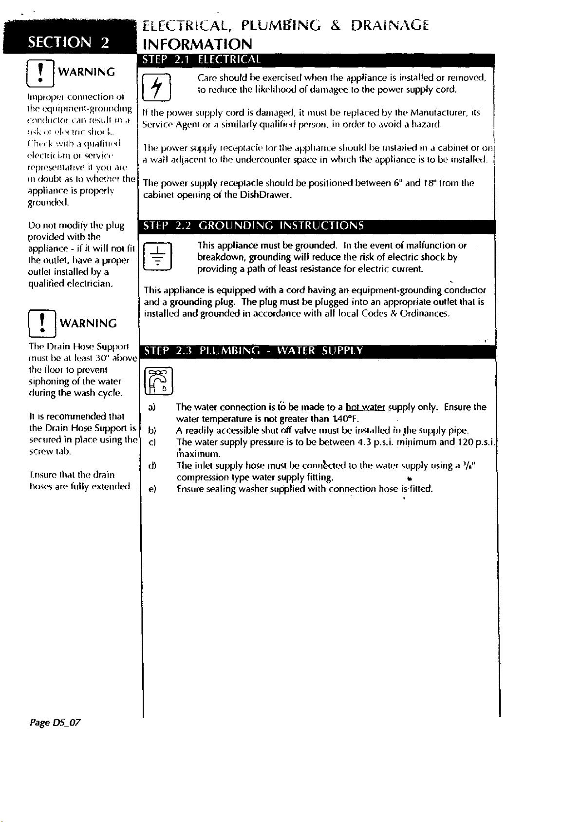
Care should be exercised when lhe appliance is installed or removed,
to reduce the likelihood of dalnagee Io lhe power supply cord.
If lhe l×)wer supply cord is daulag(_l, it nlusl be replaced by tile Manufacturer. its
Service Agenl or a similarly qualil.'d person, in order to avoid a hazard.
the power suplJi_ leceptacle for tile aplJhance sl,uuld be mslall_l in a cabinel or on
a wall adiacent Io lhe undercounter space in which the appliance is to be installed.
Tile power supply receptacle should be position,t_l between 6" and 18" from lhe
cabinet opening of the DishDrawer.
1his appliance must be grounded. In the event of malfunction or
%
This appliance is equipped with a cord having an equipment-grounding conductor
and a grounding plug. The plug must be plugged into an appropriale outlet lhal is
inslalh._l and grounded ill accordance wilh all local Codes & Ordinances.
a) The water conneclion is I'obe made to a _ supply only. Ensurethe
b) A readily accessible shut off valve must be installed ill ,thesupply pipe.
c) The water supply pressureis to be between 4.3 p.s.i, mi!limum and 120 p.s.i
d) The inlet supply hose must be connected Io the water supply usinga 3/s"
e) I-nsure sealing washer supplied with connection hose isfitted.
breakdown, grounding will reduce the risk of electric shock by
providing apalh of leasl resistance for electric current.
water temperature is not greaterthan 1.40°F.
i+laximuln.
compression type water supply fitting. _,
Page DS_07
Page 9

OishDrawer & Waste Disposal
/
VALVt
I
WASTE
WASTE DISPOSAL UNIT
HOT WATER
VALVE TOCONSTRAII_ING
P,JOle: D5602 Prefinished Model is shown. There is no variation in
plumbing belween DS602 Prefinished Model and DS6021
Integrated Mode|.
Op'Uons 1 and 2 are the preferred option.
HO_ATER
SURFACE
Page DS_08
Page 10

TIP
FITTING THE SINGLE DISHDRAWER
El_su_ethe cavity is at
least 227/_'' deep.
[_ IMPORTANT
For Inlegraled pr(xtuct
with door tilickness olhel
than _!4", tile Template
posilion must II adiust!_d
forward or back to allow
for this diflerence.
•
Draw tile cavity center
line on the supporting
cabinetry.
2_
Center Template in cavity
using V-notch on the front
of lhe Template.
o
Align front of Template to
suit surround of cabinetry.
PageDS_09
o
Mark and drill four ,sh.?,
diameter holes as
described on Template.
Page 11

I •
I ec_:lthe Power Cord,
Inh"l Hose. and Drain
+io_o thzc)tl_,!i the
Set,,4,.:e< II<fi_' l%sitior:
ih("])ish[j+av,,etit:front
otlho ni>nmr+g
1
Connect the Inlet Hose to
tlu+ HOT WATER
SUPPLY. l-_nsure the
sealing washer supplied
with the accessories is
fittled.
_ WARNING
P.nstlle the edges oI tilt,
[ •
[ t_IIlSt !X: [_lh','t*,,i ,_i:h _:,
ildg<_Frole+ ;o_ pro+i<ied
Hose coupling must be
tighlened a further hah
turn after seal conlact.
3B*
I( ,equired, the Drain
IIose may t_ Irimmed Io
a suitable length.
4_
If an air break option is
not chosen, then the
Drain l_ose Support must
l>e used and positioned
at leasl 30" above the
llo<x to l)revetlt
sil)honing ol the water
during the wash cycle.
(See Step 2.4 - Plumbing
- Drainage Options.)
e
_WARNING
D() NOI a,+|iust '+he length
o|Iite InlelI lose+
TIP
Turn the water valve ON
Io check for any leaks,
before pushing the
iI)ishl)rawer back into its
i cavity.
[_ WARNING
Attach the l)rain I lose
Support to the cabinel
cal)inelry to I)rew_nl
siphoning and 1o ke<,p lhe
Drain I lose lrom kinking.
When using a standpipe
option, hose should not
extend further than 2"
down the standpipe in
order Io preverJt
siphoning.
Page O5_10
Page 12

6. If required, trim the Single Connector to the size which matches the waste
lee or air break to Ix, used. There are ribs provided to guide cutting.
1
When using tile Single Connector, the hose should be pushed in firmly,
5 clicks.
Remember to slipthe Wire Clip over the Drain Hose belore connecting to
the Single Connector.
The supplied Wire Clip should be installed between thetwo positioning
ribson the Single Connector.
Attach SingleConnector to waste tee. (SeeStep 2.5) Ensuresnugfit
using the supplied hoseclamp,
_ WARNING
1"heProduct MUST NOT
be plugged in at this
stage.
e
Ensurethere is a power outlet in reach of tile supplied flex. If there is noi
¥
suilable outlet available then have one installed by a qualified electrician.
DO NOT modify the power plug supplied with the DishDrawer or usean
extension cord, adaptorplug or m_tiple outlet box.
o
Alternatively, the
Oisbbrawer may be
permanently connected
to flexible conduit.
Remove the flex and
cable clamp. Fit suitable
cable clamp for the
conduit and terminate
Neutral
Live
the wiring as shown.
Use the solderless lug
and washer supplied
with the product paris to
t_minate the ground
wire.
PageDS 11
Page 13

&l IaI_aa a=h:( I:] 11 }'_ I _'iILl [|]_W;N I F;TN; h_I |_1 i Ill _'W_M_;_tj | i'a
Flexible Extrusions are supplied to enable the installer to help fill any excess space
between the sides ol lhe DishDrawer and the cavity. The two lengths of Flexible
[:xlrusion (supplied) shouhl I_ attafh_ before pushing the DishDrawer into the
o+,.itv l(_+final it]staHanou Thb, I xtrusion is df'sign+_i to fit a 24" ,.,.idth cavity.
DishDrawer
Flexible Extrusions
Chassis Trim
,,,'
I. the drav, ers. exposing the chassis trin'i.
TIP
Wiring, Plunlbing and
Services sh(_uhl he
attachingthe fitt×ihi_,
(_X[l!ISiOll.
2. Remove backing from adhesive tape on Flexible._xtrusion.
e
Apply as [)er drawings, ensuring the curved edge of the Flexible Ext(usion ,
fits around lho-corner of the chassis trim. .
4.
When (:he(:king final lit, ensure DishDrawer is centered and there are even
tolerances l)etw(_n OishDrawer and cavity.
i
PageDS 12
Page 14

_ WARNING
DO NOT push against
lhe middle of the drawer.
INSERTING SINGLE DISHDRAWER INTO CAVITY
_ IMPORTANT
Make sure the inlel and
drain hose and main flex
are nol reslricled or
damaged by carefully
pulling lhem through the
• Services Hole asthe
DishDrawer is being
• pushed back into the
cavity,
] WARNING
l he l)ishDrawer should
not support any part of
the kitchen cabinetry.
Cabinet
DishDrawer
Align handle
curve wIth I"_'_
cabinet front •
3/32"
1. Position product to suit joiner,/ensuring hoses are not kinked or cut.
o
Insert M8 bolts and
washersthrough holes in
shelf.
DishDrawer
PageDS_13
Sheff
Counter top
1
Ensureproduct is
correctly positioned aod
alignedbefore lightening
e
For inslallalions where
there is a lower drawer,
insert the foam seal
provided as per Step 5.4
- Option 1.
Refel to Step 8.1 -
Installation Wet Test.
Page 15

|NFORMATION FOR CABINET MAKER FOR
INTEGRATED DISHDRAWER
!,'911I_]LI_I[,I _1
lo
Customer / Architect to Specify
Control Badgo position
Badge can [_e located anywhere within the Mounting Zone sho.,t
Handle position will need to be taken into account.
When mounting the handle ensurefastenings do not protrude
beyond the back surfaceof the Drawer Front.
Drawer Front Panel material and finish measurements are based on
%" material and cannot be less th_n 3/8"thick.
1
Work Required
Manufacture of Top Drawer FronLPanel.
Supply and insertingof four bracket screwinsertsin Drawer Front
Panel.
Drawer FronJ nlate[i,_:
/
musl be suitable for ,'ialup
conditions or ad_qualely
sealed to withstand
moisture.
Cutting of oval hole for Control Badge in earth Drawer Front Panel.
Page DS 14
Page 16

_ IMPORTANT
Recommended Drawer
Front ti_ickness for
Irltegral_,J pro(|ll(:l is
V."to %".
T] IMPORTANT
A minirnum clearance of
$/3/"must be maintained
between the Drawer
Front and existing
cabinetry, except
belween the underside of
the Drawer Front and the
shelf, where a '/d"
i clearance is needed for
Iproduct venting.
_ IMPORTANT
Dimensions for W1 and
H1 azerequired prior Io
making the Drawer Fronl.
Wl
Page DS_I 5
Page 17

le
Width Measurements (Wl)
Measure Ihe width of the cavity at the top and the bofforn, using the smaller
of the measurenrenls, subtract V_d' (_/___"each side) clearance. This is the
width dilnension for lhe Drawer Front.
Note: Allowances must be made if Drawer l_ronls are to overlap cabinetry.
IMPORTANT
All marking out 1o i_- done
on the back suriac_. _,! :i_,
Drawer Frof'd
..
Drawer Front Height (H1)
Dimensions for the height of the Drawer FrontPanel can be obtained by
measuring up from theshelfto the height of the adjoining door or cupboard
front. Sublracl1/4"to give Drawer FrontheighL The minimum heightof
the Drawer Front is 15n/_2"
ap
Badge Cutout Dimensions
Cut out Badge Mounling Hole in the chosenposition(seeMounting Zone)
usingthe "Templatediagrambelow.
Actual size of Badge
Mounting Hole shown
?
_ CAUTION
Ensure the ddll doe.s no_
damage lhelace :-
01 _ I1
Drawer Fronl.
IMPORTANT
Accuracy is'essential ,
when cutting the Badg,
Mounting Hole to ensure
a neat ill.
o
Drawer Front Mounting Bracket Nut Holes
using a ,/_/, diameter drill bit, drill out the four screw holes in each door
panel Io a deplh of 9/_6".Removeburrs.
9 17/32"
9 Ve" ._I
041[---- I_ 11/32"
6 S/16" I
----0
5 13/1S" I
w o
i
_WARNING
Use of a deplh gauge is
recommended when
drilling out holes fol
Drawer Front Mounting
Page DS 16
Page 18

IMPORTANT
A minimum clearance of
V2' is required between
the I.|llderSic/e Of tile
Drawer [ rr)ll_ a_ld
cabmelry beiow for
,.erltmg
Option 1 and Option 2 show two different slyles of cabinetry.
Option 1 shows how to seal cabinetry below the DishDrawer by using a
loarn seal provided in the accessories.
Oplion 2 shows cahmetry thai does nor require sealing.
Option 1
Page DS17
Option 2
-'i ,
s_ uM
Drlr¢_¢ F_nl
T
A
t
Page 19

INTEGRATED DRAWER FRONT INSTALLATION
There are several different colored Integrated badges to choose from. They
include black, chrome, satin & brass. Two color options are provided with
your rnachine, other optionsare available from your local Dealer.
There are five parts 1othe
Integrated Badge Assembly.
They are as follows:
1. Inlegrated Badge
2. Button Badge
3. Light Pipe
4. Electronics Board
5. BadgeCover
•
Remove BadgeCover from the Integrated Badge.
At the back of the Integrated Badge,slide the Badge Cover away from the
wire terminals.
e
Remove Electronics Board.
Gently hold the wires to remove the Electronics Board. Care should be
taken not to handle the front or back of _e Electronics Board or touch
inside the wire terminals.
t t
o
Remove the Light Pipe.
Gently tap the Integrated Badgeupsidedown on a hard surfaceuntil the
Light Pipe comes away or insert apen or pencil into the front side of the
Integrated Badge to either one of the two small holes.
J
o
Once you have removed the Electronics Board, BadgeCover and tight
Pipe, you can change the color of the Integrated Badge.
I •
Insert the Button Badgeinto the back of the Integrated'Badge. Do not
J
break any of the buttons away from the Connection Runner.
2.
Insert the Light Pipe into the Integrated Badge.
Insert the Eight Pipe with the circular ends into the small holes.
3.
h_serl the Eh!(t_onics Board with care, behind the Button Badge.
When installing the Electronics Board, handle only the wires and do not
touch lhe lace or back of the Electronics Board or inside the wire
terminals.
4. Slide the Badge Cover into the slot on top of the Integrated Badge.
Button Badge"
"1'
Connection l_Ui_ll_,;
PageDS_18
Page 20

_ WARNING
Care should Ix_ laken ill
the following steps.
_ CAUTION
Take care n<)tit) damage
ifront surfac:t-"ol panel.
[nstlre all cuts are
straight and cart+'is taken
to avoid damage to the
)rawer Front.
_ CAUTION
Overlightening will
damage the Drawer
Front.
•
Remove Drawer Front
Mounling Panel by
withdrawing pins from
sides of drawers using
long nosed pliers.
in a downwards a'nd
outwardsmotion.
from the Electronics
Panel.
Using an Allen Key, scre_
in Mounting Bracket Nuts.
Remove Burrs. Screw in
flush with back surface.
4o i
Fit the Door Mounting
Panels usingthe screws
supplied.
im
PageDS_+9
5.
Feed wires through to
the back and press
badge into hole, if
needed adherebadge to
Drawer Frontwith a
glue or silicon sealant.
1
Fit the customer
supplied handle.
Refer to Step 6.1 -
Points to Consider.
Page 21

TIP
•
] CAUTION
The rubber seal belwe_l_
lhe Drawer and Drawel
Frontmust be kept in
_lace.
e
Plug lhe grounding v, ire
onto the panel
Connect badge wires to
integrated badge port on
Electronics Board.
1
Fit Drawer Front by
sliding in an upwards
and inwards motion.
o
Ensurethe slide hooks
(on slide) are as far
forward as possible as
shown, then inserl pins
to lock in place,
ensuring thal the rib on
lhe pin is vertical.
_ WARNING
The Electr01;ics Board i_
an eleclroslalic Se.nsiliv_"
device. £nsure you are
adequalely grounded
when connecting or
disconnecting the badge
by wearing a gro,.mdirtg
strap or by grounding
ourself.
_ WARNING
Ensure the product is nol
plugged in.
CORRECl
i'! i.ii
i!__ !_ _i! _!
Check fit of the Drawer
Frontand adiust if
required.
INCORRECT
X
Page DS_20
Page 22

FINAL FITTING FOR SINGLE DISHDRAWER
Counter top
•
Check Hnal fit _I
Dishl )m',vet m (1_vI!_1.
I
Tighten M_ oolls.
DishDrawer
Shelf
Page DS_21
Page 23

FINAL CHECKS
Ensureproduct is level, securely fastened to lhe floor and opens
and closesfreely.
Ensure inlel hose to faucet (-onneclion is tightened to specification.
Insure any knockoutsor plugs in drain connection have lxeen
dr ed out and dra n connection made to specification.
Plug in and turn ON the power and water supply. The DishDrawer
should"beep" and light up.
Open the drawers of the DishDrawer and check operation of
Secondary Control Panel and check sprayarm(s) are in place and
free to rotate.
b. Select Rinse program on the Secondary Control Panel and close the
drawers.
7. Staff the Programby pressing the Start/Pausebutton.
8. After tile program has finished, check underneath the DishDrawer
for water leakage. Ensure machine has,jun and drained correctly.
9. Check water supply and drainage connection for leakage.
[]
[]
5
[]
[]
[]
[]
[]
[]
10. Repeatfor each Drawer.
l,'JllNlli[l![ml |_o_! _oze_
•
Water underneath DishDrawer, check the hose connections and
hose for leaks_
2.
Water around water supply and drainage connections - check
connections, existing plumbing and hoses for leaks.
3.
Excessivewater remaining above the filter plate, after the rinse
cycle, check for kinked drain hosesor blocked was_ connection.
4.
No water supply, check water is on and there is water pressure.
5.
If a faull occurs, consult the Problem Solver Section of the Use &
Care Manual.
6. If unable Io resolve, conlacl Cuslomer Care C'enler.
Ensure Power is connected and is switched ON.
[]
] .
.O
[]
[]
[]
[]
[]
Ensure the water supply is connected and ON.
LEAVE ALL LITERATURE WITH THE CUSTOMER.
[]
Page DS_22
Page 24

 Loading...