

24'' Single DishDrawer™
DD24SI9-N
Place settings 7
Features
Tub Carbon Polymer
Audible End-of-Cycle Signal Yes
Control Type Interior Digital Control
Rinse Aid Dispenser With indicator
Wash System
Automatic Temperature Control Yes
Variable Water Pressure Yes
Washing System SmartDrive™
Eco options Yes
Cycles
Wash Cycles 6
Exterior Appearence
Appearance Custom Panel Ready
Racking
Support with Adjustable Storage Interval
2
(near or distanced)
Flexible utility shelf system 4 - adjustable
Rack coating Nylon with graphite color
Maximum Plate Height 11 1/2''
DryIndex
Fan-Assist Dry Yes
Heating Element Multi-Wattage
Economical / Quiet
Energy Star Qualified Yes
Direct Drive Motor Yes
Water Consumption 1,7 gallons per drawer
Options
Start / Pause / Reset Yes
Delay Start Yes - Up to 12 hours
Child lock Yes
Automatic Child Lock Once Started Yes
Electrical Requirements
Volts; Hertz; Amps 120V / 60Hz / 5.0 amp
Energy Consumption ENERGY STAR | 137 kWh per year
Dimensions
Overall Height (in.) 16 1/8''
Overall Width (in.) 23 9/16''
Closed Drawer Depth (in.), Excluding
22 15/16''
Handle
Opened Drawer Depth (in.), Excluding
44 1/8''
Handle
Accessories (optionnal)
Stainless Steel Panel ADDD24S-N | For DishDrawer DD24SI9-N
Warranty
1 Year full Warranty Entire appliance; parts and labour, in-home
service
Powered by TCPDF (www.tcpdf.org)
The information contained herein is based on sources that we believe to be reliable, but is not guaranteed by us,
may be incomplete or may change without notice
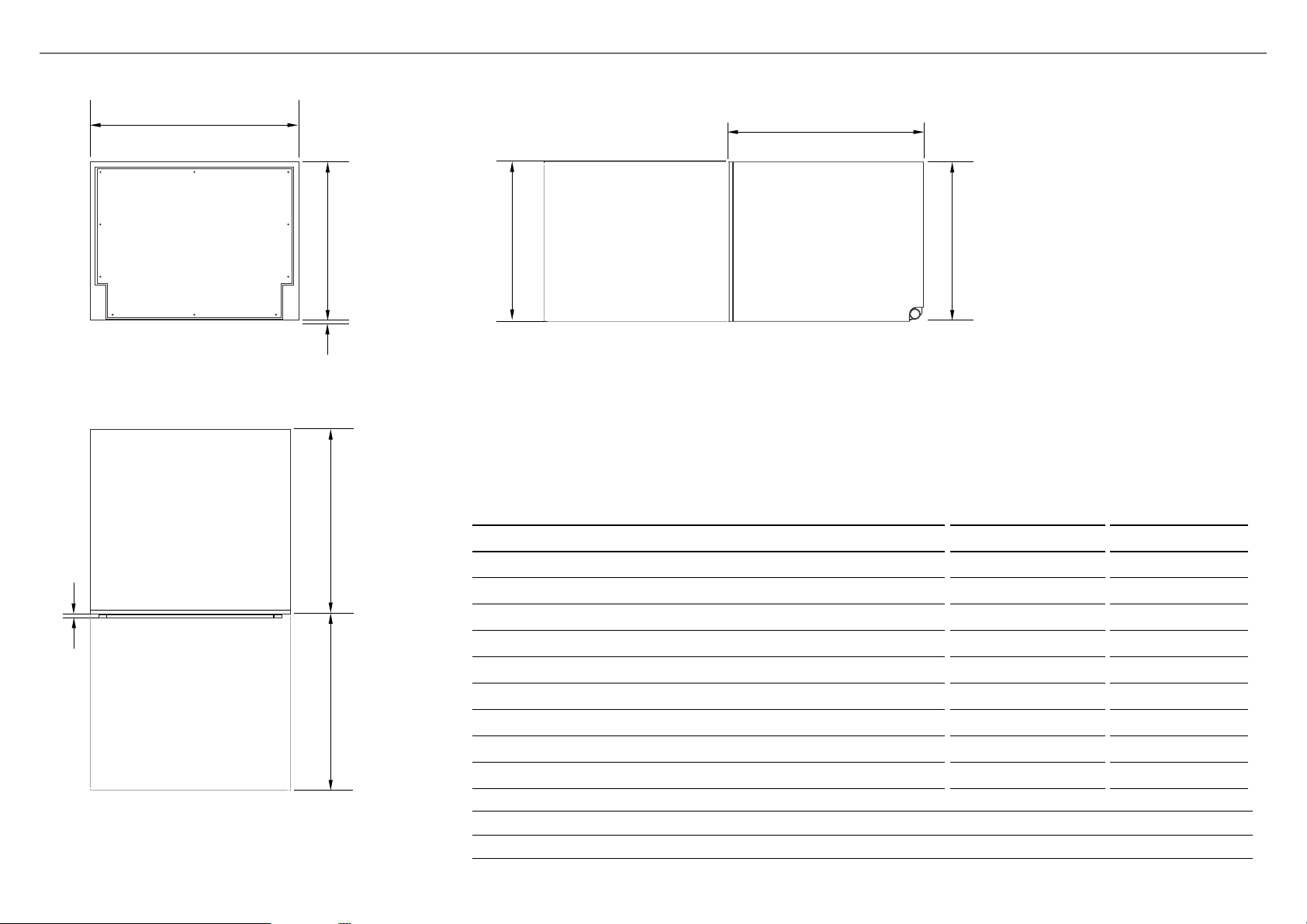
PRODUCT DIMENSIONS
E
B
PLAN
A
H
D
I
C
F
PROFILEFRONT
PRODUCT DIMENSIONS INCHES (MM) INCHES (MM)
Overall height of product
A
Overall width of product
B
Overall depth of product
C
Depth of chassis (to back of front drawer panel)
D
Depth of drawer front panel
E
Height of drawer front panel min. 16 1/16” (408)
F
Height of chassis
G
Ventilation gap below drawer front panel
H
Maximum extension of drawer
I
1
includes 1 ⁄16” (2mm) high bracket slots 2 assuming a front panel thickness of 11/16” (18mm)
3
recommended for a 1 ⁄16” (2mm) ventilation gap below panel, if cavity height is 16 1/4” (412mm)
4
recommended for a 1 ⁄16” (2mm) ventilation gap below panel
1
1
2
2
G
STANDARD
HEIGHT
MODELS
DD24SI
16 1/8” (410) min. 17 7/8” (454)
23 9/16” (599) 23 9/16” (599)
22 1/2” (571) 22 1/2” (571)
21 3/4” (553) 21 3/4” (553)
5/8” - 13/16” (16-20) 5/8” - 13/16” (16-20)
3
min. 17 13/16” (452)
16 1/8” (410) 17 7/8” (454)
min. 1/6” (2) min. 1/6” (2)
21 7/16” (545) 21 7/16” (545)
TALL
HEIGHT
MODELS
DD24STI
DD24SHTI
4

K
CABINETRY DIMENSIONS
L
Bracket slots
PLAN
STANDARD
HEIGHT
MODELS
DD24SI
CABINETRY DIMENSIONS INCHES (MM) INCHES (MM)
Inside height of cavity
J
Inside width of cavity
K
Inside depth of cavity
L
min. 16 1/4” (412) min. 18” (456)
23 5/8” (600) 23 5/8” (600)
min. 22 1/16” (560) min. 22 1/16” (560)
Minimum clearances from adjacent cabinetry
TALL
HEIGHT
MODELS
DD24STI
DD24SHTI
J
PROFILE
Custom Filler Panel
J
min. 1/2” (13 mm)
clearance from a
corner cupboard
min. 1/16” (2 mm)
clearance to adjacent
cupboard door
If your cavity height leaves a visible gap
under your countertop when you open
the drawer:
Fit the supplied cavity bracket (or
a custom cavity filler panel) before
installation in order to conceal any
gap at the top of the cavity left after
installation.
PROFILE

COUNTERTOP
3/8”
(10mm)
Moisture
protection
tape must
be applied.
CAVITY PREPARATION
IMPORTANT!
The power outlet
must be located in a
cabinet adjacent to the
dishwasher cavity.
110-120 VAC max. 15 A
Water Connection
These marks indicate
formed bracket
screw locations, if
securing by drawer
removal.
If there is no side
partition, you can
construct timber
bracing as something
to secure into.
IMPORTANT!
Adjacent cabinetry must not
extend above cavity base.
ø max. 1 1/2” (38mm)
Services can be
located either side
of dishwasher.
Services hole
Can be located either side of dishwasher, preferably
at the bottom of the cavity, as shown. If adequate
clearance, services hole can be made higher to clear
toekick space. If hole is higher, ensure drain hose(s) are
routed straight into the waste connection.
●
If the hole is through wood, make sure its edges are
smooth and rounded.
●
If the hole is through metal, ensure you fit the supplied
Edge Protector to prevent damage to the power cord.
Recommended HOT
(Maximum 140°F/60°C).
Supplied hose to suit
3/8” (9 mm) male
Water Pressure
Water softener models
Max. 1 MPa (145 psi)
Min. 0.1 MPa (14.5 psi)
Models without
water softener
Max. 1 MPa (145 psi)
Min. 0.03 MPa (4.3 psi)
max. 17 11/16”
(450mm)
min. 7 7/8” (200 mm)

min. 21 inches
29 in.-34 ¾ in.
Minimum distance from the ground to provide for
connecting the drain hose
IMPORTANT!
Please note: These instructions are complementary to your installation guide. Please refer to the
installation guide given with your appliance in order to get all required instructions.
DD24SI9-N
 Loading...