

Page 1
SAFETY AND WARNINGS
Important safety precautions!
Particular attention shall be given to the relevant requirements regarding ventilation.
Please make this information available to the person installing the appliance as it could reduce your
installation costs.
This appliance is to be installed and connected to the electricity and gas supply only by an authorised
person.
Installation must comply with your local building and local gas authority codes and electricity
regulations.
Failure to install the appliance correctly could invalidate any warranty or liability claims.
These appliances are registered in: (New Zealand) at www.ess.govt.nz and (Australia) with SAI Global
at www.saiglobal.com.
This gas appliance is suitable for connection to natural gas only. If in doubt, refer to the local gas
network operator or gas supplier to conrm gas type at installation site.
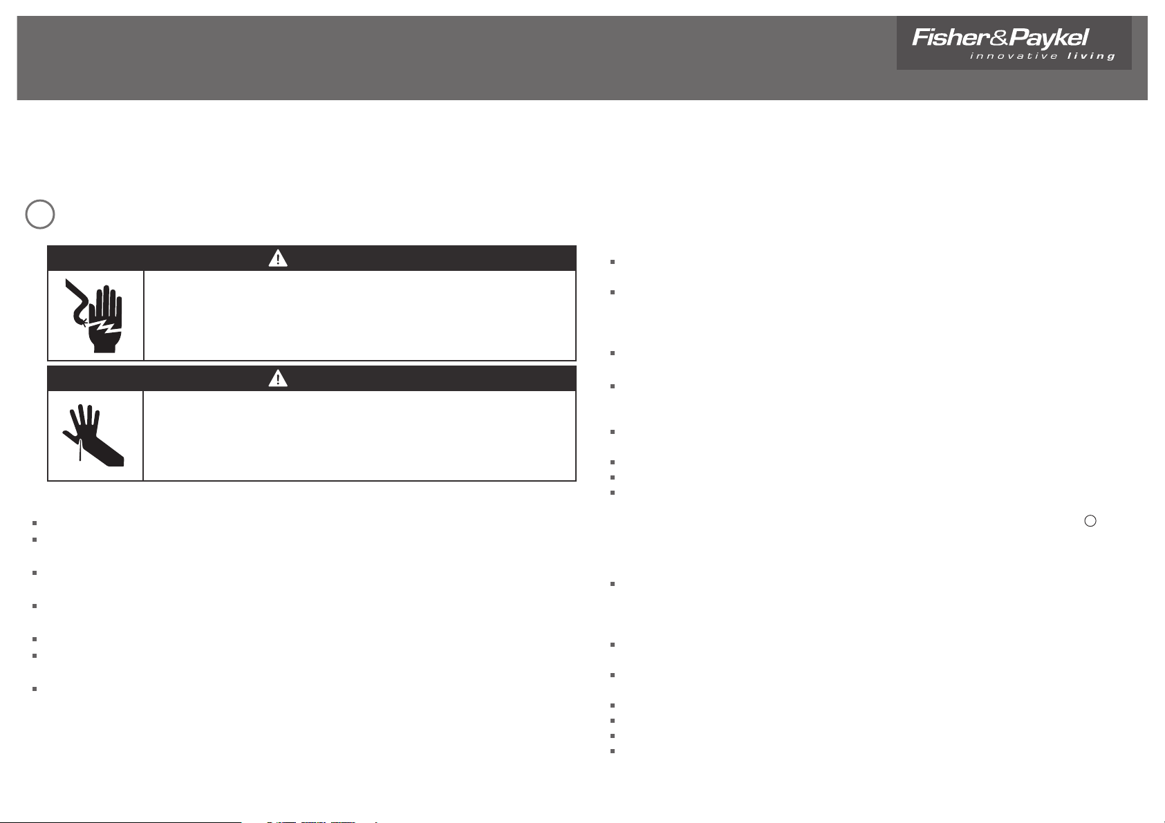
WARNING!
Cut hazard
Take care - panel edges are sharp.
Failure to use caution could result in injury or cuts.
WARNING!
Electrical shock hazard
Disconnect appliance from main power supply before continuing.
Failure to do so could result in electrical shock or death.
Before you install the appliance, please make sure that
the local distribution conditions (nature of gas and pressure) and the adjustment of the appliance
are compatible. For adjustment conditions for this appliance, see ‘Gas rate summary’
a suitable disconnection switch is incorporated in the permanent wiring, mounted and positioned to
comply with the local wiring rules and regulations. A means of disconnection with at least a 3 mm
air gap contact separation in all poles must be incorporated into the xed wiring in accordance with
the wiring rules, unless the local wiring rules allow for alternative means
the appliance is connected to a 220V - 240V 50Hz (10 A) power supply only and earthed via the
power supply cable
there is a power outlet within reach of the power supply cable (900 mm from the centre rear of the
product). This must be accessible after installation. The power supply cable should not touch any
metal parts
if the power supply cable is damaged, it is replaced only by the special cable: Part no. 531953 - Flex
Terminal Block Assy NZ/AU, obtainable from authorised Fisher & Paykel Service Agents
the supply connection point (gas shut-o valve) is accessible after installation
the benchtop is made of a heat resistant material
the installation complies with all the requirements of Australian and New Zealand Gas Installation
Standards (AS5601, NZS5261), including that the product has to be installed so that the surface
temperature of any nearby combustible surface will not exceed 65
O
C above ambient. See 3
‘Clearance Dimensions’.
When you install the appliance
We do not recommend you ush mount or seal this appliance into the bench with silicone or glue.
Doing so will make future servicing dicult. Fisher & Paykel will not be liable for any costs associated
with removing or replacing a sealed-in appliance, nor for repairing any damage that may be incurred
by doing this.
Seal exposed bare edges of the cutout with an oil-based paint or moisture-proof polyurethane to
prevent possible moisture creeping between the cooktop trim and the benchtop.
We do not recommend the use of a down-draught extractor fan with the appliance, as it may distort
the ame pattern, causing uneven heating and reduced cooking performance.
Where this appliance is installed in marine craft or in caravans, it shall not be used as a space heater.
No combustible material or products should be placed on this appliance at any time.
Do not spray aerosols in the vicinity of this appliance while it is in operation.
If, after following the instructions given, the appliance cannot be adjusted to perform correctly,
please refer to the Service & Warranty book for warranty details and your nearest Authorised Service
Centre, Customer Care, or contact us through our website: www.sherpaykel.com.
1
IZONA CookSurface
Installation instructions
CG903ML & CG903MLD models
NZ AU
Page 2
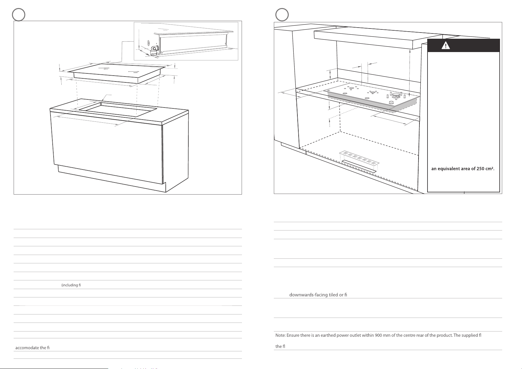
PRODUCT & CABINETRY DIMENSIONS CLEARANCE DIMENSIONS
Product and cabinetry dimensions (mm)
CG903ML
IZONA
CG903MLD
IZONA DEEP
A
overall height of product (including retracted dials/pan supports) 96 96
B
overall width of product 900 900
C
overall depth of product 410 530
D
height of chassis (below top of bench) 89 89
E
width of chassis 856 856
F
depth of chassis 384 480
G
depth of chassis tted elbow*) 424 480
H
overall width of cutout 865 865
I
overall depth of cutout 390 494
J
corner radius of cutout max. 10 max. 10
K
distance from top of bench to centre of gas inlet on product 64 64
L
distance from edge of chassis to gas inlet on product 20 20
Note: *(CG903ML models only) If benchtop thickness exceeds 50 mm, additional cutout space will be required to
tted elbow.
Installation diagrams for illustration purposes only
Note: Gas inlet connection is
located in the back left corner.
Clearances (mm)
CG903ML
IZONA
CG903MLD
IZONA
DEEP
A
minimum clearance from left edge of product to nearest combustible surface 60 60
B
minimum clearance from right edge of product to nearest combustible surface 80 80
C
minimum clearance from rear edge of product to:
nearest combustible surface
nearest non-combustible surface
100
10
10
10
D
minimum height of non-combustible material when used on adjacent walls 150 150
E
minimum clearance from glass surface to:
rangehood
any other overhead exhaust fan
downward facing combustible surface
re resistant surface
650
800
650
500
650
800
650
500
F
minimum clearance below top of benchtop to:
combustible surface
Fisher & Paykel oven or nearest non-combustible surface
115
100
115
100
G
cutout measuring 50 x 500 mm for air intake grill. Ensure air can easily enter the area around the base of
the product from the room in which the product is installed
exible
hose must be used between the product gas inlet and the connector on the wall which should be 650 - 750 mm above
oor and towards the left-hand end of the product. It should be accessible with the product installed.
A
B
C
G
D
E
F
32
A
B
C
E
D
F
H
I
J
K
L
G*
WARNING!
The CookSurface requires
adequate air supply to fully
function. The base of the
CookSurface must have direct
unrestricted ventilation to the
room where the CookSurface
is installed. Do not ventilate
the base area to an external
area that can be at dierent
air pressure to that of the
burners. You may ventilate
from adjacent cupboards, but
ensure that the available air
supply will not be restricted.
The ventilation area must
be 500 x 50 mm or of an
equivalent area. If the 50 mm
wide slot is not possible due
to the width of the available
toe recess, increase the length
of the slot so as to maintain
An air intake grill is provided.
Ensure that the grill is not
covered or obstructed.
Flush
Page 3
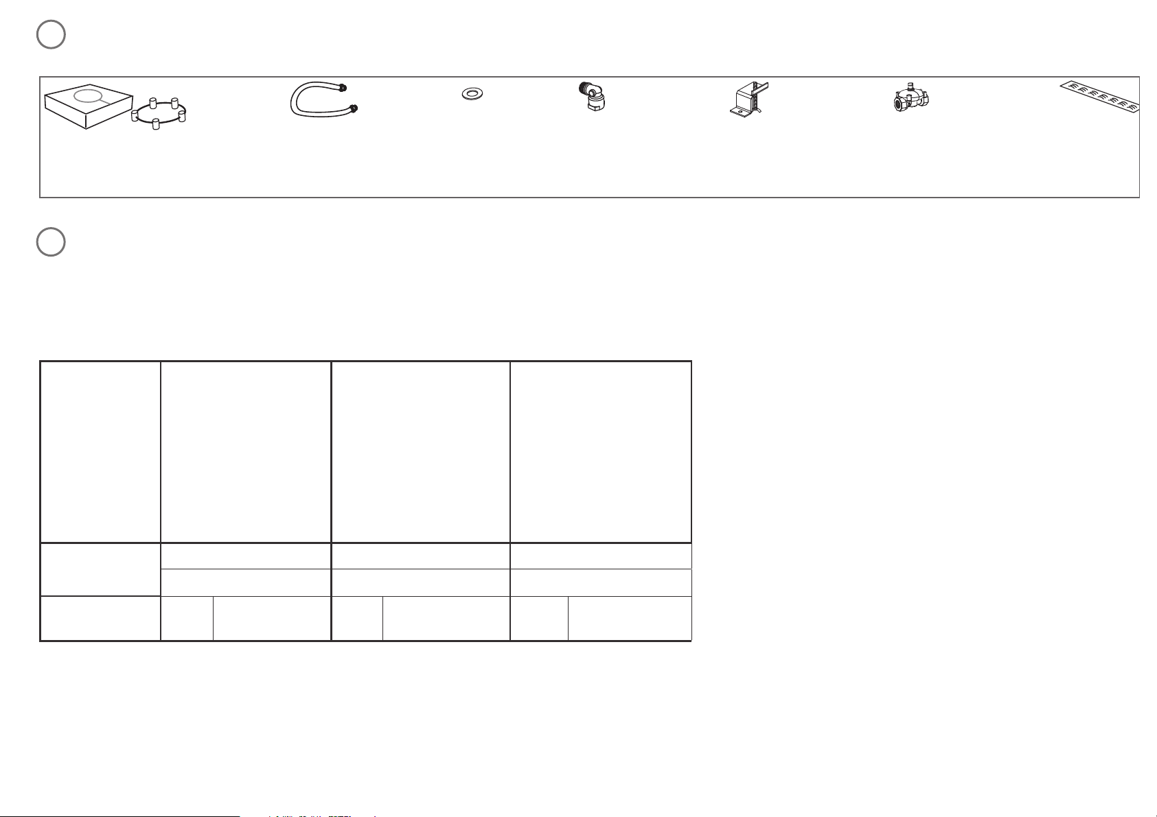
PARTS SUPPLIED
Wok stand (1)
Flexible
hose (1)
Blue washer (1)
GAS RATE SUMMARY
All appliances are factory set for natural gas and are not currently convertable to LPG.
NZ AU
Injector orice (mm)
Nominal rating (MJ/h)
Injector orice (mm)
Nominal rating (MJ/h)
Injector orice (mm)
Nominal rating (MJ/h)
NG (1.0 kPa)*
SMALL MEDIUM WOK
NG NG NG
CG903ML &
CG903MLD
1.09Y 7.2 1.15Y 8.0 1.65 12.8
*Nominal pressure with the two smaller burners on High.
Elbow
3
/
8
“ NPT (1) Clamping
brackets (4)
and screws (4)
NG regulator (1) Air intake
grill (1) and
screws (6)
4
5
Page 4

FLUSH MOUNTING INSTALLATION
(NOT RECOMMENDED)
A
B
C
E
D
F
H
H
Top view
I
H
I
I
I
I
Product and cabinetry dimensions (mm)
CG903ML
IZONA
CG903MLD
IZONA
DEEP
A
overall height of product (including dials/pan supports) 96 96
B
overall width of product 900 900
C
overall depth of product 410 530
D
height of chassis (below top of bench) 94 94
E
width of chassis 856 856
F
depth of chassis 384 480
G
depth of chassis tted elbow) 424 480
H
overall width of routered recess 905 905
H
I
width of cutout 865 865
I
overall depth of routered recess 415 535
I
I
depth of cutout 390 494
J
corner radius of cutout max. 10 max. 10
K
distance from top of bench to centre of gas inlet on product 64 64
L
distance from edge of chassis to gas inlet on product 20 20
M
corner radius of routered recess max. 2 max. 2
N
height of routered recess 5 5
M
K
L
M
N
J
1
1
2
2
x 4
20-50 mm
5 mm
3
min. 150 OC rated
TO REMOVE PRODUCT
1
2
BA
DC
F
E
WARNING!
We do not recommend ush
mounting and sealing as servicing
requires the CookSurface to be
removed from the benchtop. The
owner carries all risk for ush
mounting the CookSurface.
The owner must ensure the
CookSurface has been cut out
from the benchtop before
servicing can be carried out. Fisher
& Paykel will not be liable for any
costs associated with removing
or replacing a ush-mounted
and/or sealed-in product, nor for
repairing any damage that may be
incurred by doing this.
G
6
Ensure silicone does
not leak underneath glass.
Fresh air from
outside cabinetry
view from below
Ret existing
screw to secure
into basepan
For benchtops thicker than
50 mm, reverse the clamping
brackets, as shown in 11
Apply tape/foam
inside recess to stop
silicone leaking underneath.
Page 5

REMOVE FROM PACKAGING ENSURE THERE IS ADEQUATE AIR SUPPLY
FIT THE ELBOW & FLEXIBLE HOSE LOWER GENTLY INTO THE CUTOUT
87
19 0
PTFE
” NPT
1
2
1
1
2
A
Ensure there is enough
exible hose looped to
allow for removing
appliance for servicing.
A
Important!
The exible hose supplied
must be used to enable servicing.
500 mm
50 mm
A A
The CookSurface requires adequate air supply to fully function. The base of the CookSurface must have direct
unrestricted ventilation to the room where the CookSurface is installed. Do not ventilate the base area to an
external area that can be at dierent air pressure to that of the burners. You may ventilate from adjacent
cupboards, but ensure that the available air supply will not be restricted. The ventilation area must be
500 x 50 mm or of an equivalent area. If the 50 mm wide slot is not possible due to the width of the available toe
recess, increase the length of the slot so as to maintain an equivalent area of 250 cm
2
. An air intake grill is provided.
Ensure that the grill is not covered or obstructed.
Page 6

SECURE THE PRODUCT TO THE BENCHTOP CONNECT TO THE GAS & ELECTRICAL SUPPLY
CHECK FOR GAS LEAKS TEST OPERATION
1 32 4
A
Test operation by
lighting all burners.
13 14
11 12
GAS
ON
A
GAS
ON
20-50 mm
1
2
50+ mm
1
2
x 4
A
Fresh air from
outside cabinetry
Fresh air from
outside cabinetry
Ret existing
screw to secure
into basepan
view from below
For benchtops thicker than 50 mm,
reverse the clamping brackets, as shown
Ret existing
screw to secure
into basepan
NG
NG
½ “ BSP
A
Ensure the blue washer is tted
B
Page 7

www.sherpaykel.co.nz www.sherpaykel.com.au 599760A NZ AU 03.09
FINAL CHECKLIST
TO BE COMPLETED BY THE INSTALLER
Have you installed the clamping brackets?
Have you allowed for adequate air supply to the product?
Have you used the supplied exible hose and blue washer?
Have you leak-tested all connections?
Is the regulator set to the correct working pressure?
Have you placed the supplied duplicate data plate on an adjacent surface?
Is the CookSurface earthed?
Check that the power supply cable is NOT touching the CookSurface.
OPERATION:
Do all burners ignite both individually and in combination?
Are the ames consistent and appropriately sized?
Have you demonstrated the basic operation to the customer?
Installer’s name:
Installer’s signature:
Installation company:
Date of installation:
LEAVE THESE INSTRUCTIONS WITH THE CUSTOMER
15
 Loading...