

Page 1

OUTDOOR GRILL
36 & 48" BE models
GRIL EXTÉRIEUR
Modèles 36 et 48" BE
INSTALLATION GUIDE/USER GUIDE
GUIDE D’INSTALLATION/GUIDE D’UTILISATION
US CA
Page 2

Page 3

CONTENTS
Safety and warnings 3
Grill models 6
Product dimensions 7
Installation
Locating grill / built-in clearances 8
Built-in construction details 13
Gas hook-up 15
Leak testing 18
Electrical connection 19
Burner adjustment 20
Radiant assembly 21
Installer checklist 22
Using the grill
Lighting instructions 24
Grilling 25
Using the grates 32
Using the charcoal insert 33
Using the rotisserie 34
Accessories 39
Care & maintenance 40
Troubleshooting 44
Warranty and Service 45
EN
IMPORTANT!
SAVE THESE INSTRUCTIONS
The models shown in this user guide may not be available in all markets and are subject to change
at any time. For current details about model and specification availability in your country, please
visit our website listed on the back cover or contact your DCS by Fisher & Paykel dealer.
1
Page 4

A MESSAGE TO OUR CUSTOMERS
Thank you for selecting this DCS Evolution Series Grill. This installation and user guide contains
valuable information on how to properly install, operate and maintain your new appliance for
years of safe and enjoyable cooking.
Please fill out and submit your Product Registration by visiting our website at www.
dcsappliances.com and selecting “Support” on the home page and then selecting “Product
Registration”. In addition, keep this guide handy, as it will help answer questions that may arise as
you use your new appliance.
For your convenience, product questions can be answered by a DCS Customer Care
Representative at www.dcsappliances.com, or email: customer.care@fisherpaykel.com.
Please write the model, code, and serial numbers on this page for reference (this can be found on
the inside, right side panel behind the drip pan handle. See page 22.)
MODEL NUMBER CODE SERIAL NUMBER
IMPORTANT!
DO NOT discard any packing material (box, pallet, straps) until the unit has been inspected.
Inspect the product to verify that there is no shipping damage. If any damage is detected, call
the shipper and initiate a damage claim. DCS by Fisher & Paykel is not responsible for shipping
damage.
2
Page 5
SAFETY AND WARNINGS
To reduce the risk of fire, electrical shock, injury to persons, or damage when using the appliance,
follow the important safety instructions listed below:
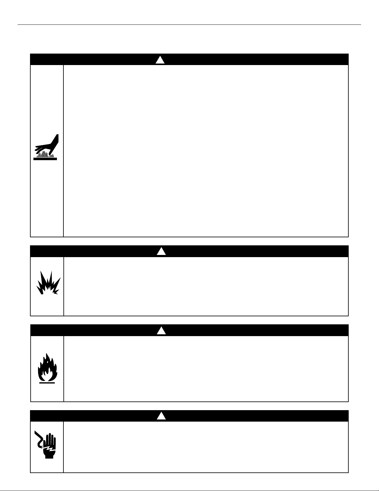
!
WARNING!
Hot Surface Hazard
Accessible parts may become hot during use.
Do not touch surface units or areas near units of the grill.
Hood must be opened before lighting the grill.
Never let clothing or other flammable materials come in contact with or get too close
to any grate, burner or hot surface until it has cooled. Fabric may ignite and result in
fire or personal injury.
Never lean over an open grill. When lighting a burner, always pay close attention to
what you are doing. Be certain you are pushing the burner knob when you attempt to
light the grill.
When using the grill, do not touch the grill burner, grate, or immediate surrounding
area as these areas become extremely hot and could cause burns.
Grease is flammable. Never operate the grill without a grease tray. Let hot grease cool
before attempting to handle it. Avoid letting grease deposits collect in the drip pan.
Clean the grill with caution. Avoid steam burns; do not use a wet sponge or cloth to
clean the grill while it is hot. Some cleaners produce noxious fumes or can ignite if
applied to a hot surface.
Use only dry potholders; moist or damp potholders on hot surfaces may cause burns
from steam. Do not use a towel or bulky cloth in place of potholders. Do not let
potholders touch hot portions of the grill or burner grate.
To avoid burns when cooking, use long handled BBQ tools.
Failure to follow this advice may result in burns and scalds or serious injury.
EN
!
WARNING!
Explosion Hazard
If you smell gas, do not use the appliance.
Do not use water on grease fires, a violent steam explosion may result. Turn all burners
off, then smother fire or flame or use dry chemical or foam-type extinguisher.
Do not heat unopened food containers such as cans – Build up of pressure may cause
container to burst and result in injury.
Failure to follow this advice may result in injury or death.
!
WARNING!
Fire Hazard
Do not operate the grill under un protected combustible construction. Use only in
well ventilated areas. Do not use in buildings, garages, sheds, breezeways, covered
structures or other such enclosed areas. This unit is for outdoor use only.
Never leave the grill unattended when in use.
Never store a spare LP cylinder under or near this unit.
Never fill the tank beyond
Failure to follow this advice may result in death or serious injury.
Electrical Shock Hazard
This appliance is equipped with a three-prong or four-prong grounding plug for
your protection against shock hazard and should be plugged directly into a properly
grounded power outlet. Do not under any circumstances cut or remove the grounding
prong from this plug.
Failure to follow this advice may result in death or electrical shock.
full.
¾
!
WARNING!
3
Page 6

SAFETY AND WARNINGS
IMPORTANT SAFETY INSTRUCTIONS!
y After a period of storage or non-use (such as over the winter), the gas grill should be checked for
gas leaks, deterioration, proper assembly, and burner obstructions before using.
y Always use a covered hand when opening the grill hood and only do so slowly to allow heat and
steam to escape.
y After lighting burners, make sure burners are operating normally (see page 20).
y Do not use aluminium foil to line drip pans or grill grates or radiants. This can severely upset
combustion air flow or trap excessive heat in the control area. The result of this can be melted
knobs or damaged ignition components.
y Do not operate with a damaged cord or plug, after the appliance malfunctions or after the
appliance has been damaged in any manner. Contact the manufacturer for repair.
y Do not let the rotisserie cord hang over the edge of a table or touch hot surfaces.
y Do not use an outdoor cooking appliance for purposes other than intended.
y Do not use lighter fluid in the charcoal burner insert or on the gas burners.
y Be sure all grill controls are turned off and the grill is cool before using any type of aerosol
cleaner on or around the grill. The chemical that produces the spraying action could, in the
presence of heat, ignite or cause metal parts to corrode.
y Never grill without the drip pan and grease tray in place and hooked into the front of the grease
tray (see Fig. 34 on page 40 for diagram). Without it hot grease could leak downward and
produce a fire or explosion hazard.
y If you are using griddle plates, do not place them side by side on the grill or on top of the
Infrared Hybrid Burner.
y Never use the grill in a windy area.
y Do not try lighting this appliance without reading the “LIGHTING INSTRUCTIONS” section of this
manual.
y Do not locate, store or operate the grill on an inclined plane.
y Keep any electrical supply cord, or the rotisserie motor cord away from the heated areas of the
grill and water (pools, fountains, puddles).
y Never use a dented or rusty LP tank. Keep the ventilation openings of the cylinder enclosure free
and clear from debris.
y Have an ABC rated Fire Extinguisher accessible – never attempt to extinguish a grease fire with
water or other liquids.
y Do not move the appliance during its use.
y Do not operate in enclosed areas. This could result in carbon monoxide build-up which would
result in injury or death.
y When using a grill, be sure that all parts of the unit are firmly in place and that the grill is stable
(can’t be tipped over).
y To put out flare-ups, adjust the controls to lower the temperature
y Do not ignite the grill burners while the rotisserie burner is lit.
y Never attach or disconnect an LP cylinder, or move or alter gas fittings when the grill is in
operation or is hot.
y CALIFORNIA PROPOSITION 65-WARNING: the burning of gas cooking fuel generates some
by-products which are on the list of substances which are known by the State of California to
cause cancer or reproductive harm. California law requires businesses to warn customers of
potential exposure to such substances. To minimize exposure to these substances, always operate
this unit according to the manual, ensuring you provide good ventilation when cooking with gas.
y This outdoor cooking gas appliance is not intended to be installed in or on recreational vehicles,
trailers and/or boats.
y This product must be installed by a licensed plumber or gas fitter when installed within the
Commonwealth of Massachusetts.
4
Page 7

SAFETY AND WARNINGS
IMPORTANT SAFETY INSTRUCTIONS!
y Certain Liquid Propane dealers may fill liquid propane cylinders for use in the grill beyond
cylinder filling capacity. This “overfilling” may create a dangerous condition. “Overfilled” tanks
can build up excess pressure. As a safety device, the tank pressure relief valve will vent propane
gas vapor to relieve this excess pressure. This vapor is combustible and therefore can be ignited.
To reduce this danger, you should take the following safety precautions:
y When you have your tank filled, be sure you tell the supplier to fill it to no more than
of its total capacity.
y If you own or use a spare tank, or have a disconnected tank, you should NEVER store it near
or under the grill unit or heat box, or near any other ignition or heat source. A metallic sticker
with this warning is provided with the grill. Install this sticker close to your barbeque grill.
y Do not store a full tank in direct sunlight.
y Push in and turn the selected control knob to HI/SEAR position. Release the knob when the
burner lights. If burner does not light in four to five seconds, turn knob “OFF” and wait five
minutes before trying again so any accumulated gas may dissipate.
y Before each use, inspect the gas supply piping or hose prior to turning the gas “ON”. If there is
evidence of cuts, wear, or abrasion, it must be replaced prior to use.
y Follow the installation instructions within this manual. Have your grill installed by a qualified
installer. Have the installer show you where the gas supply shut-off valve is located so that you
know where and how to shut off the gas to the grill. If the connections are not perfectly sealed,
you can have a small leak and therefore a faint gas smell. Some leaks can only be found with the
burner control in the “ON” position - this must be done by a qualified technician.
y Children should not be left alone or unattended in an area where the grill is being used. Never
allow them to sit, stand or play on or around the grill at any time. When in use, portions of the
grill get hot enough to cause severe burns.
y Do not store items of interest to children around or below the grill.
y Clean and perform general maintenance on the grill twice a year. Watch for corrosion, cracks,
or insect activity. Check the regulator, hoses, burner ports, air shutter, and venturi/valve section
carefully. Always turn off gas at the source (tank or supply line) prior to inspecting parts.
y Never use the grill burners while the rotisserie burner is lit.
(75%)
¾
EN
5
Page 8
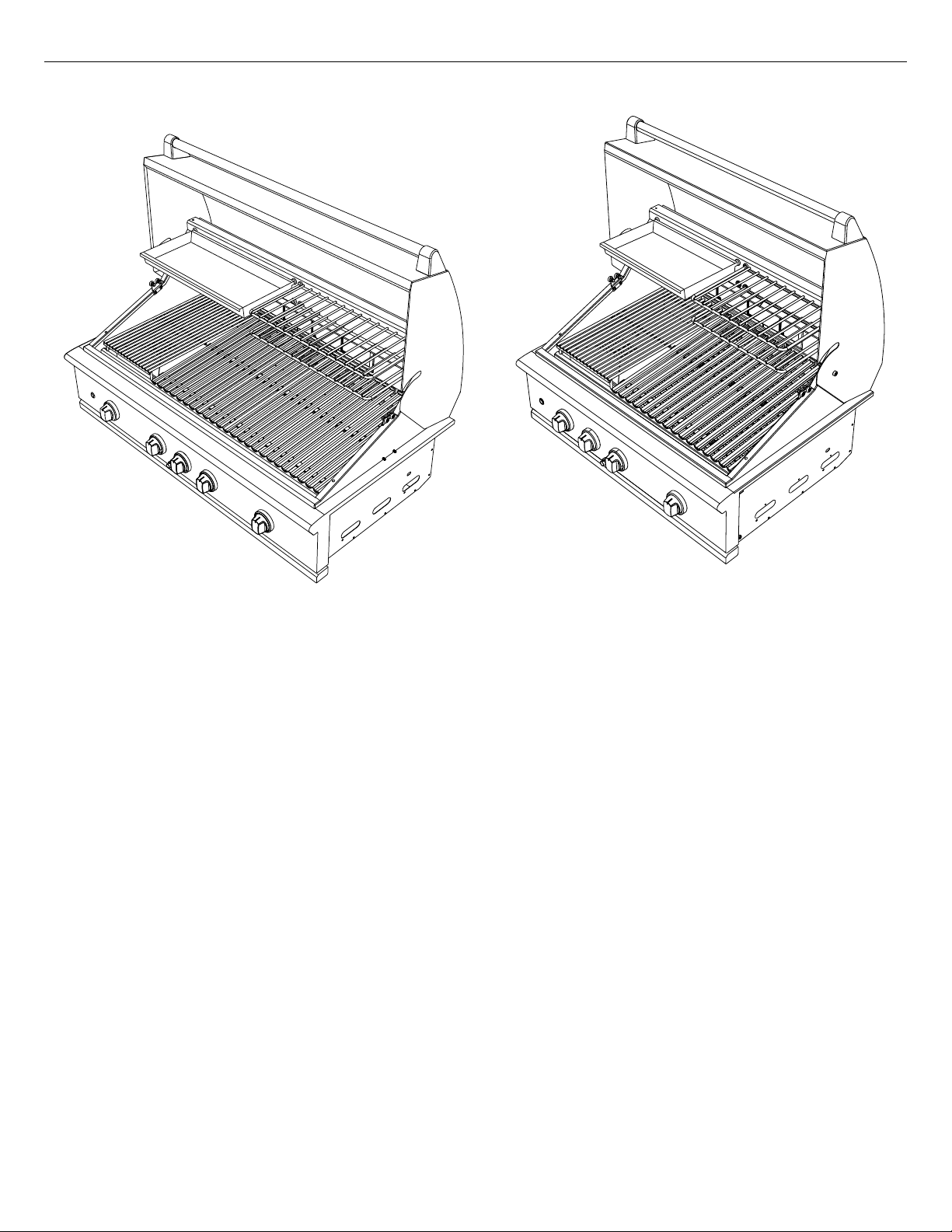
GRILL MODELS
BE1-36RBE1-48R
6
Page 9
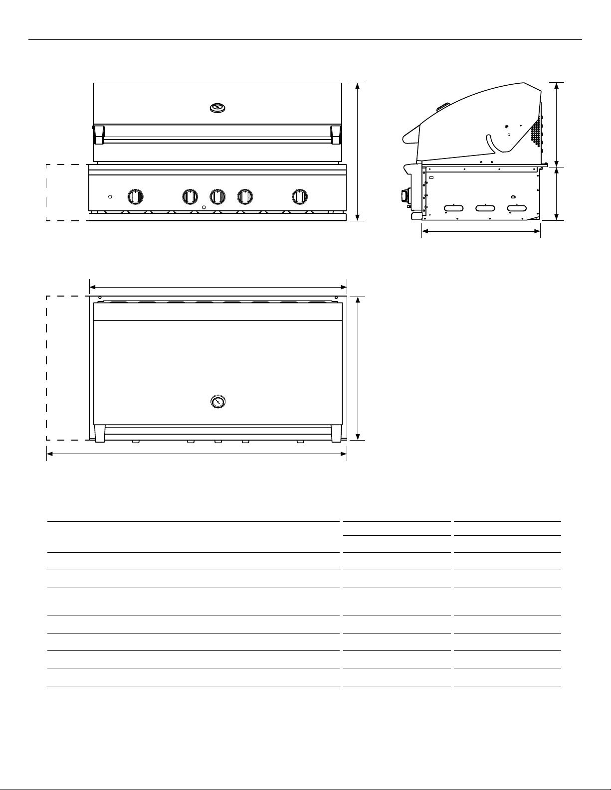
PRODUCT DIMENSIONS
A
B
EN
f
e
d
G
PRODUCT DIMENSIONS
A
Overall height of grill
B
Overall width of grill
Overall depth of grill
C
(excluding handle and dials)
D
Depth of chassis
E
Height of chassis
f
Height of hood
G
Overall width of grill with storage unit attached
c
BE1-48R Model Illustrated
BE1-48R BE1-36R
Inches (mm) Inches (mm)
27 1/4" (692) 27 1/4" (692)
47 15/16" (1217) 35 15/16" (912)
26 7/8" (682) 26 7/8" (682)
22" (559) 22" (559)
9 15/16" (252) 9 15/16" (252)
17 7/16" (443) 17 7/16" (443)
53 15/16" (1369) 23 7/16" (1065)
7
Page 10

INSTALLATION
Locating Grill/Built-in Clearances
IMPORTANT!
Before installation, remove shipping brackets from the grill.
Loosen the four screws. Slide the shipping bracket off and
re-tighten the screws.
Location
When determining a suitable location, take into account concerns such as exposure to wind,
proximity to traffic paths and keeping any gas or electrical supply lines as short as possible and away
from heat sources. Locate the grill only in a well ventilated area. Do not build the grill under overhead
unprotected combustible construction. Never locate the grill in a building, garage, breezeway, shed
or other such enclosed areas. During heavy use, the grill will produce a lot of heat and smoke. Ensure
that the grill is used in a well ventilated area.
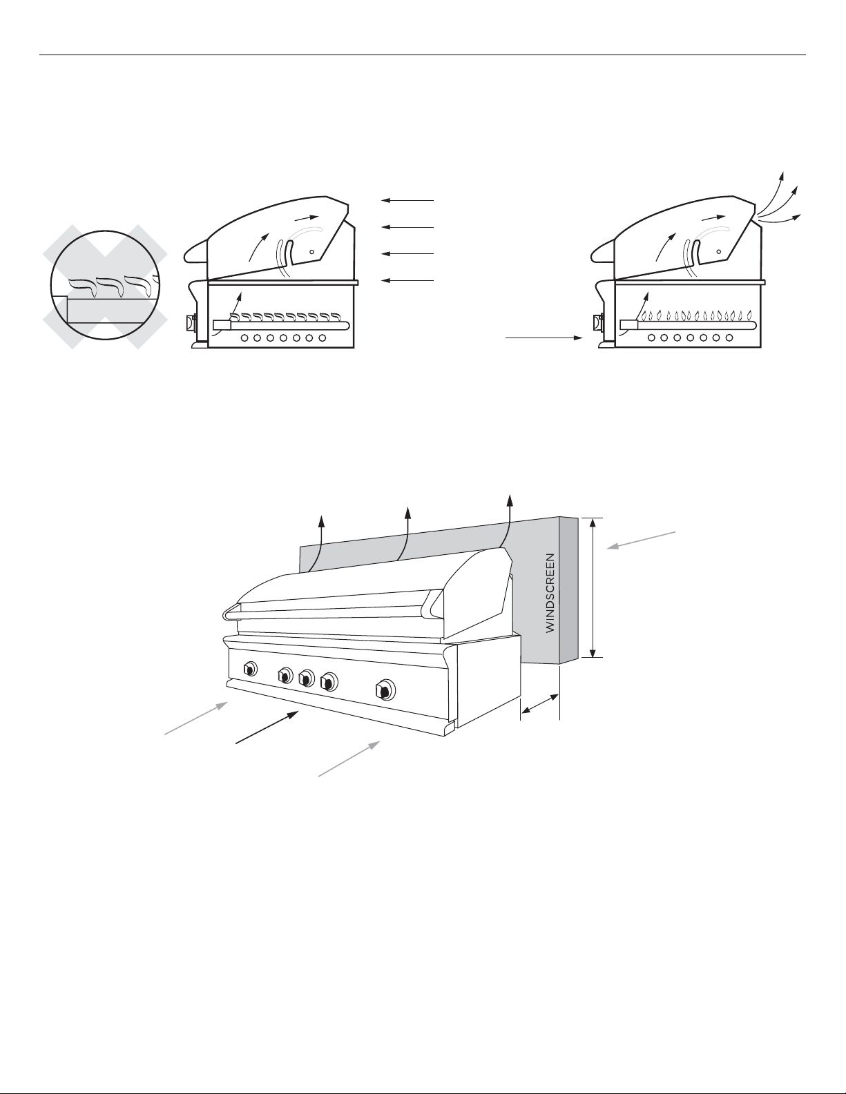
If locating the grill in a windy area, try to locate the grill so the prevailing wind will blow air at the
front of the grill as shown in Fig. 01b. This will assist the grill in venting hot air through the back of
the grill. In addition, this will help keep any smoke from blowing at someone who is cooking on the
grill. If you have to locate the grill in a windy area where the prevailing wind is at the rear of the
grill (Fig. 01a), a windscreen must be installed. The windscreen
wind from entering the exhaust vent in the rear of the unit as shown in Fig. 01c. Location of the
windscreen relative to rear of the grill must adhere to the clearances specified for combustible or
non-combustible construction as defined in these instructions. Refer to following pages.
should be set-up so that it blocks
As a high-performance gas appliance, your grill requires significant amounts of air to support the
combustion process. Your grill is designed to take air in through the valve panel area, and send the
exhaust products out through the exhaust gap at the rear of the hood. Using your grill in windy
conditions can disrupt the proper flow of air though your grill, leading to reduced performance, or in
certain severe cases, causing heat buildup in the valve panel area. This can lead to problems such as
having the knobs melt, or burn hazards when the valve panel surfaces become too hot to touch.
Please note that damage to your grill resulting from use in windy conditions, such as melted knobs or
igniter wires, or valve panel discoloration from heat build-up, are excluded from warranty coverage.
8
Page 11
INSTALLATION
Locating Built-in Clearances
IMPORTANT!
Gas fittings, regulator, and installer supplied shut-off valves must be easily accessible.
EN
GRILL EXHAUST
EXHAUST
WIND
DIRECTION
EXHAUST
FLAME LIFT
PREFERRED
AIR FLOW
FIG. 01a FIG. 01b
Wind hitting the grill while in use, (especially wind blowing into or across the hood gap) can cause
poor performance and in some cases can cause the control panel to get dangerously hot.
EXHAUST VENT FLOW
WIND
15” (381 mm) min.
WIND
PRIMARY INTAKE
AIR FLOW
WIND
FIG. 01c
3” (76 mm) min. for
non-combustibles
18” (457 mm) min.
for combustibles
If wind is an issue, a windscreen should be added. The windscreen should be higher than the top of
the opening in the back of the grill, with a minimum clearance of 3” (76mm) for non-combustibles,
or 18” (457mm) for combustibles, from the back of the grill
9
Page 12
INSTALLATION
Locating Built-in Clearances
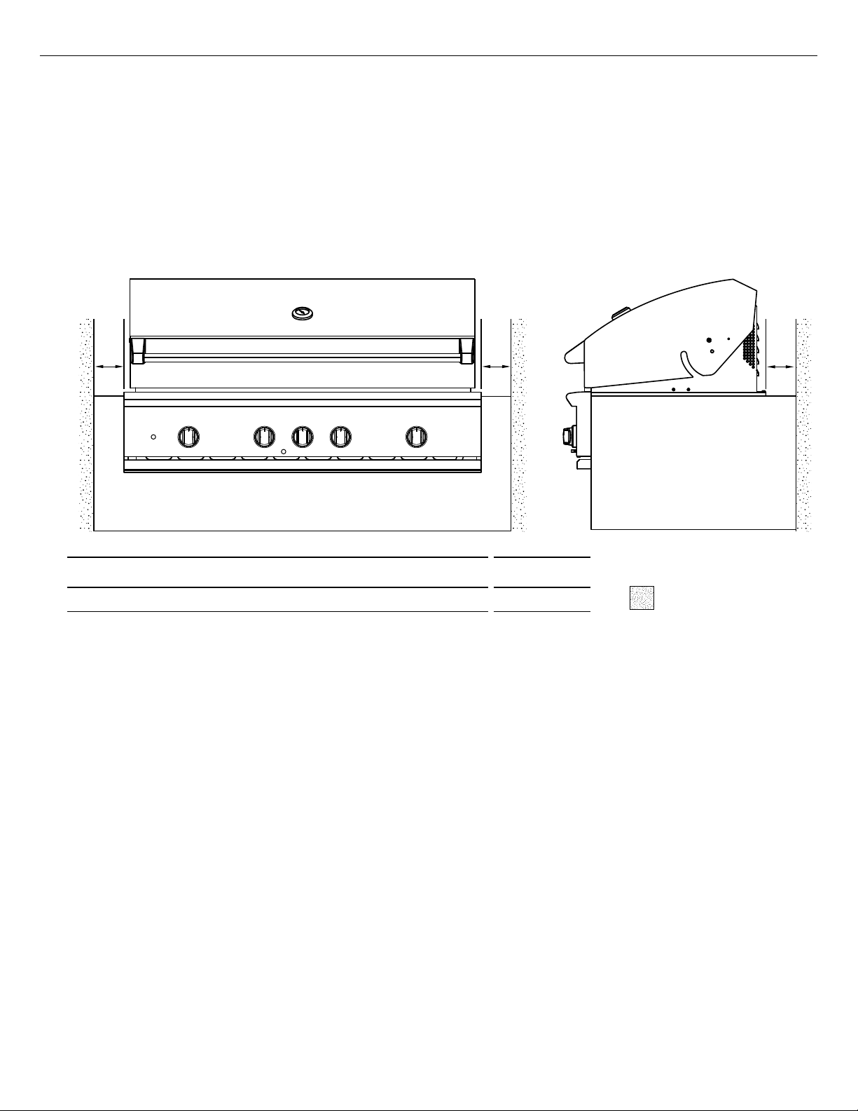
Clearances to non-combustible construction*
A minimum of 3” (76mm) clearance from the back of the grill to non-combustible construction
is required for the purpose of allowing the hood to open fully. It is desirable to allow at least 6”
(153mm) rear and side clearance to non-combustible construction above the cooking surface for
counter space. If you’ll be using the rotisserie option, the space is essential for motor and skewer
clearance. The grill can be placed directly adjacent to non-combustible construction below the
cooking surface (Fig. 02).
Note: if intending to use the rotisserie, the minimum clearance will be from the rotisserie motor
instead of the side of the grill.
A A A
FIG. 02
PRODUCT DIMENSIONS INCHES (MM)
NON-COMBUSTIBLE
A
Minimum distance from non-combustible surface to grill
3"
(76)
=
SURFACE
*DEFINITION OF NON-COMBUSTIBLE MATERIAL - Material which is not capable of being ignited and
burned, such as materials consisting entirely of, or a combination of, steel, iron, brick tile, concrete,
slate, and plaster.
General
The grill is designed for easy placement into built-in masonry enclosures. For non-combustible
applications the grill drops into the opening shown in Fig. 05 and hangs from its side flanges. A
deck is not required to support it from the bottom. When using the insulated jacket in a combustible
enclosure application, see the Fig. 06. The insulation jacket assembly must be supported from the
bottom by a ledge on each side and back or a solid deck.
A spirit level should be used to ensure that the unit is level both front-to-back and side-to-side. If
it is not level, burner combustion may be erratic or the unit may not function efficiently for grease
flow. If the floor is uneven, re-leveling may be required whenever a freestanding unit is moved.
IMPORTANT!
y Failure to maintain required clearances creates a fire hazard that may result in property damage or
serious personal injury.
y The grill is designed to function in an open area. Recommended minimum clearances should be
maintained to all surfaces (combustible and non-combustible) for optimum performance. Noncombustible material within the minimum clearance area could result in discoloration or deterioration.
y If a non-combustible material such as stucco is covering a combustible material such as wood, the
minimum clearance distance needs to be considered for wood. The presence of a non-combustible
material inside the clearance zone does not eliminate the minimum clearance zone to combustible
material.
10
Page 13
INSTALLATION
Locating Built-in Clearances
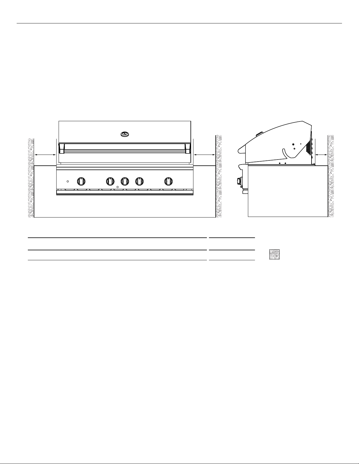
Clearances to combustible construction**
Minimum of 18” (457mm) from the sides and rear of grill must be maintained to adjacent vertical
combustible construction, above the counter top level. Intense heat, and large volumes of smoke will
exhaust from the rear of the grill (Fig. 01b). This may discolor or damage unprotected areas. Do not
install under unprotected combustible construction without using a fire safe ventilation system.
A 18” (457mm) minimum clearance must be maintained under the counter top to combustible construction. The clearance can be modified by a use of an insulated jacket. Insulated jackets can be
purchased from our website, www.dcsappliances.com.
AA A
EN
FIG. 03
PRODUCT DIMENSIONS INCHES (MM)
A
Minimum distance from combustible surface to grill
18" (457)
COMBUSTIBLE
=
SURFACE
**DEFINITION OF COMBUSTIBLE MATERIAL - Any materials of a building structure or decorative
structure made of wood, compressed paper, plant fibers, vinyl/plastic or other materials that
are capable of transferring heat or being ignited and burned. Such material shall be considered
combustible even though flame-proofed, fire-retardant treated or surface-painted, or plastered.
IMPORTANT!
It is required that a minimum of three 10x10" (645 x 645mm) of ventilation opening be provided for
both the left and right sides, as well as the back of enclosure (Fig. 05), in order to safely dissipate
unburned gas vapors in the event of a gas supply leak.
Insulated jacket
If the grill is to be placed into a combustible enclosure, an approved insulated jacket is necessary.
Insulated jackets are available from your dealer. Use only the DCS insulated jacket which has
specifically been designed and tested for this purpose. Review the detail drawing shown (Fig. 06)
and take into account the provisions shown for gas line hook-up clearance in the right rear corner.
It is required that ventilation holes are provided in the enclosure to eliminate the potential build-up
of gas in the event of a gas leak. The supporting ledges or deck must be level and flat and strong
enough to support the grill and insulated jacket. The counter should also be level.
IMPORTANT!
Installing this product into a combustible enclosure without an insulated jacket could result in fire,
property damage and personal injury.
11
Page 14
INSTALLATION
Locating Built-in Clearances
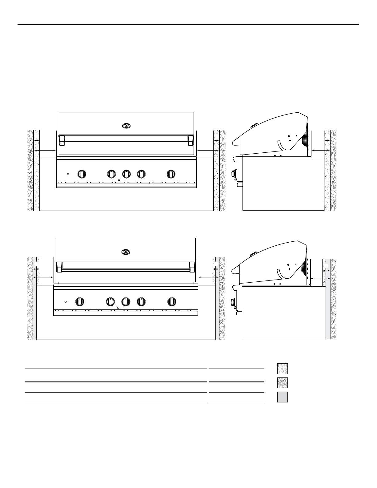
Clearances to protected combustible construction***
A minimum of 12" (305mm) clearance from the sides and rear of grill must be maintained to adjacent
vertical protected combustible construction. Intense heat, and large volumes of smoke will exhaust
from the rear of the grill. This may discolor or damage unprotected areas. The 12" (305mm) includes
4" (102mm) min. non-combustible material plus an additional 8" (203mm) min. clearance between
the grill and the protected combustible construction. This can be achieved by brick or concrete (Fig.
04a) or a metal stud finished with non-combustible substrate (Fig. 04b).
A
FIG. 04a
B B
A
BB
AA
A
B
A
B
FIG. 04b
NON-COMBUSTIBLE
=
PRODUCT DIMENSIONS INCHES (MM)
A
Minimum non-combustible surface width
B
Minimum distance from combustible surface to grill
4"
(102)
12" (305)
SURFACE
COMBUSTIBLE
=
SURFACE
METAL STUD
=
***DEFINITION OF PROTECTED COMBUSTIBLE SURFACE - A wall of non-combustible material in
front a wall of combustible material, to act as a barrier. For definitions of non-combustible and
combustible material, please refer to previous pages.
12
Page 15
INSTALLATION
Built-in Construction Details
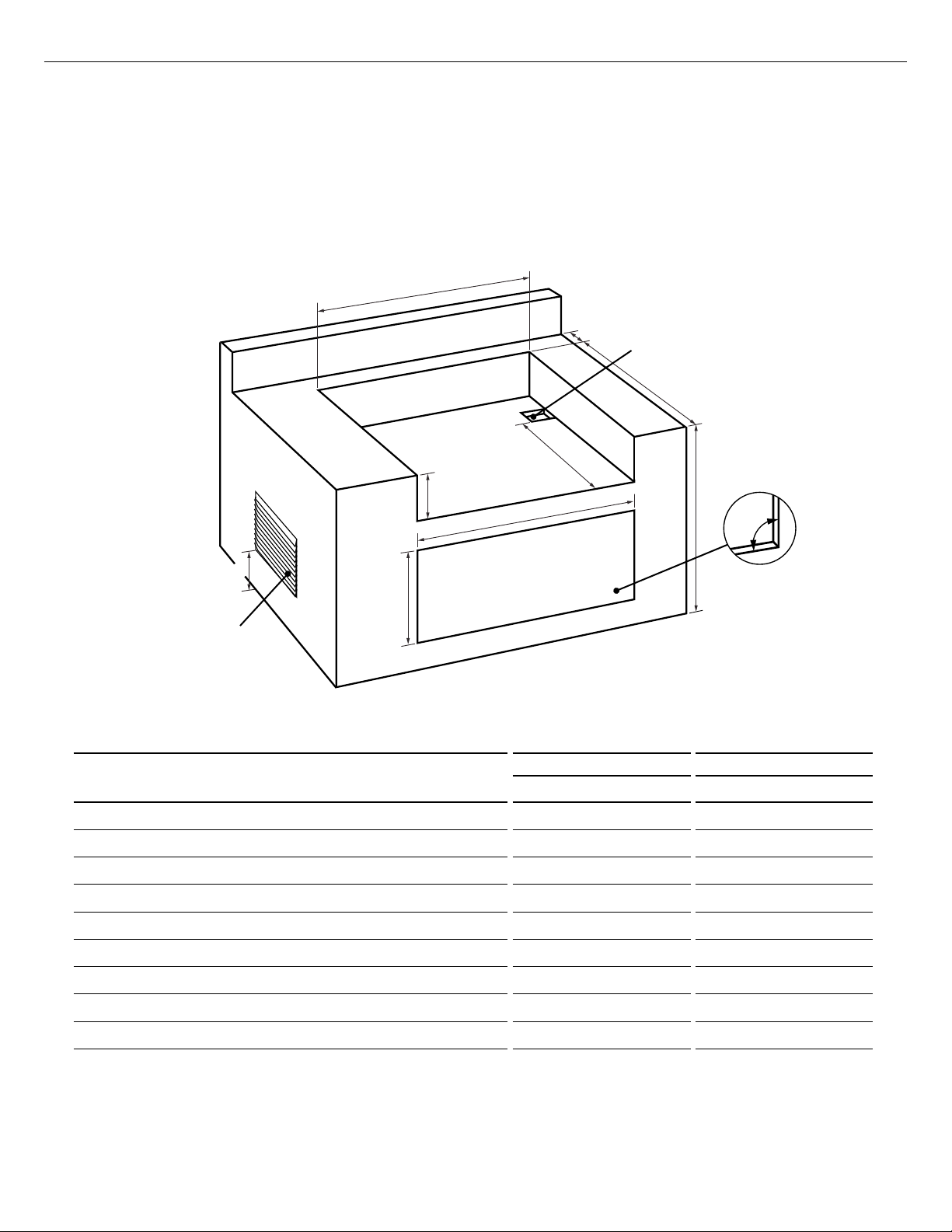
Standard layout for non-combustible cavity
IMPORTANT!
If installing the grill into a non-combustible enclosure, all combustible construction must still be
outside the 18" (457mm) clearance zone. If your island is made of stucco over the top of wooden
studs, the wood can not be inside the 18 inch clearance zone to combustible, even though the stucco
is what is touching the grill area.
D
EN
G
Note: vents are to be located at the left,
right and rear of the enclosure. Minimum
size of all vents is 10x10" (645mm x 645mm)
CAVITY DIMENSIONS
H
E
FIG. 05
I
F
C
Note: 4x4” (102 x 102mm)
opening for gas supply line
B
A
Note: the cut-out of each
corner should be a 90°angle
in order for the access doors/
drawers to fit properly.
BE1-48R BE1-36R
Inches (mm) Inches (mm)
A
Maximum height of enclosure shell
B
Depth of enclosure shell
C
Minimum depth for hood swing
D
Width of enclosure cavity
E
Height of enclosure cavity
f
Depth to gas supply opening
G
Height to base of vents
H
Height of opening for access doors/drawers
I
Width of opening for access doors/drawers
35 1/2" (902) 35 1/2" (902)
22 3/4" (578) 22 3/4" (578)
3 3/4" (95) 3 3/4" (95)
45 3/4" (1162) 34 1/2" (876)
10 1/8" (257) 10 1/8" (257)
18 1/2" (464) 18 1/2" (464)
1" (25) 1" (25)
20" (508) 20" (508)
46" (1168) 34" (864)
13
Page 16

INSTALLATION
A
Built-in Construction Details
Standard layout for cavity including insulated jacket
D
F
Note: 4x4” (102mm x 102mm)
C
opening for gas supply line
B
G
Note: vents are to be located at the left,
right and rear of the enclosure. Minimum
size of all vents is 10x10" (645mm x 645mm)
CAVITY DIMENSIONS
A
Maximum height of enclosure shell
B
Depth of enclosure shell
C
Minimum depth for hood swing
D
Width of enclosure cavity
E
Height of enclosure cavity
f
Depth to gas supply opening
G
Height to base of vents
H
Height of opening for access doors/drawers
I
Width of opening for access doors/drawers
E
H
I
Note: the cut-out of each
corner should be a 90°angle
in order for the access doors/
drawers to fit properly.
FIG. 06
BE1-48R BE1-36R
Inches (mm) Inches (mm)
35 1/2" (902) 35 1/2" (902)
22 3/4" (578) 22 3/4" (578)
3 3/4" (95) 3 3/4" (95)
51 5/8" (1318) 40 1/2" (1029)
11 1/8"(283) 11 1/8"(283)
18 1/2"(464) 18 1/2"(464)
1" (25) 1" (25)
20" (508) 20" (508)
46" (1168) 34" (864)
14
ACCESS DOORS
MODEL NUMBER
ACCESS DRAWERS
MODEL NUMBER
CAVITY WIDTH CAVITY HEIGHT
Inches (mm) Inches (mm)
ADN1-20x48 ADR2-48 46" (1168) 20" (508)
ADN1-20x36 ADR2-36 34" (864) 20" (508)
ADN1-20x30 ADR2-30 28" (711) 20" (508)
ADN1-20x24 ADR2-24 22" (559) 20" (508)
To order access drawers or doors, please visit www.dcsappliances.com for further details.
Page 17
INSTALLATION
Gas Hook-up
Gas requirements
Verify the type of gas supply to be used, either natural or LP, and make sure the marking on the
appliance rating plate agrees with that of the supply. The rating plate is located on the underside of
the drip tray. Never connect an unregulated gas line to the appliance. You must use a gas regulator
even if the supply is controlled.
An installer-supplied gas shut-off valve must be installed in an easily accessible location. All installer
supplied parts must conform to local codes, or in the absence of local codes, with the National
Electrical Code, ANSI/NFPA 70 or the Canadian Electrical Code, CSA C22.1, and the National
Fuel Gas Code, ANSI Z223.1 or CSA-B149.1 Natural Gas Installation Code or CSA-B149.2 Propane
Installation Code.
All pipe sealants must be an ap proved type and resistant to the actions of LP gases. Never use
pipe sealant on flare fittings. All gas connections should be made by a qualified technician and
in accordance with local codes and ordinances. In the absence of local codes, the installation
must comply with the National Fuel Gas Code ANSI Z223.1. Gas conversion kits are available from
Customer care. When ordering gas conversion kits, have the model number, and the type of gas
(natural or LP) from your grill.
Total gas consumption of the grill with all burners on HI
BE1-48R - 118,000 Btu/hr or 124.5 Mj/hr BE1-36R - 89,000 Btu/hr or 93.3 Mj/hr
The appliance and its individual shut-off valve must be disconnected from the gas supply piping
system during any pressure testing of that system at test pressures in excess of 1/2 PSIG (3.5 kPa).
The appliance must be isolated from the gas supply piping system by closing its individual manual
shut-off valve during any pressure testing of the gas supply piping system at test pressures equal to
or less than 1/2 PSIG (3.5 kPa). The installation of this appliance must conform with local codes or,
in the absence of local codes, with the National Fuel Gas Code, ANSI Z223.1/NFPA 54. Installation in
Can ada must be in accordance with Natural Gas and Propane Installation Code, CSA B149.1, and/or
Propane Storage and Handling Code, B149.2 and local codes.
EN
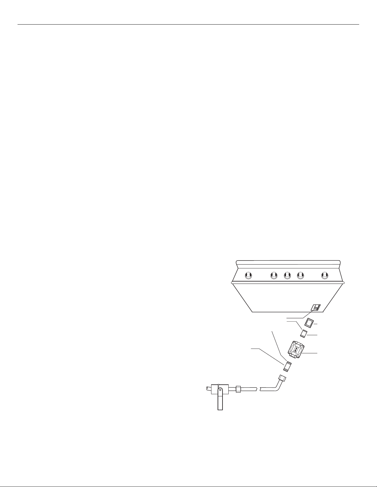
Natural gas built-in hook-up
(This should be performed by a technician only.)
Connection: 1/2” NPT female. Operating pressure:
4.0” W.C. Supply pressure: 5” to 14” WC. If in excess
of 14” W.C. a step down regulator is required. Check
with your local gas utility company or local codes
for instructions on installing gas supply lines. Be
sure to check on type and size of run, and how deep
to bury the line. If the gas line is too small, the grill
will not function properly. Any joint sealant used
must be an approved type and be resistive to the
actions of LP gases.
To hook-up the fittings supplied with the grill
Assemble as shown (Fig. 07). Use threading
compound on male threads only. Use a second pipe
wrench to hold the grill inlet pipe to avoid shifting
any internal gas lines of the grill. Ensure that the
regulator arrow points in the direction of gas flow
towards the unit, away from the supply. Do not
forget to place the installer-supplied gas valve in an
accessible location.
Threading compounds
(Must be resistant to
LP gas)
1/2” NPT x
5.0" Nipple
Installer supplied
shut-off valve must be
easily accessible*
*Installation must conform
with local codes or with the
National Fuel Gas Code ANSI
Z223.1 or the CSA-B149.2
Propane Installation Code
Bottom of unit
Coupling
1/2” NPT
x 2.0”
NIpple
Regulator
4.0" W.C.
FIG. 07 Natural Gas
15
Page 18
INSTALLATION
Gas Hook-up
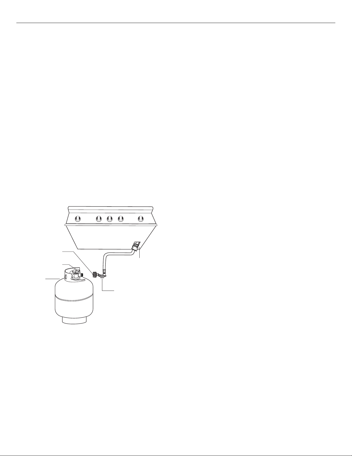
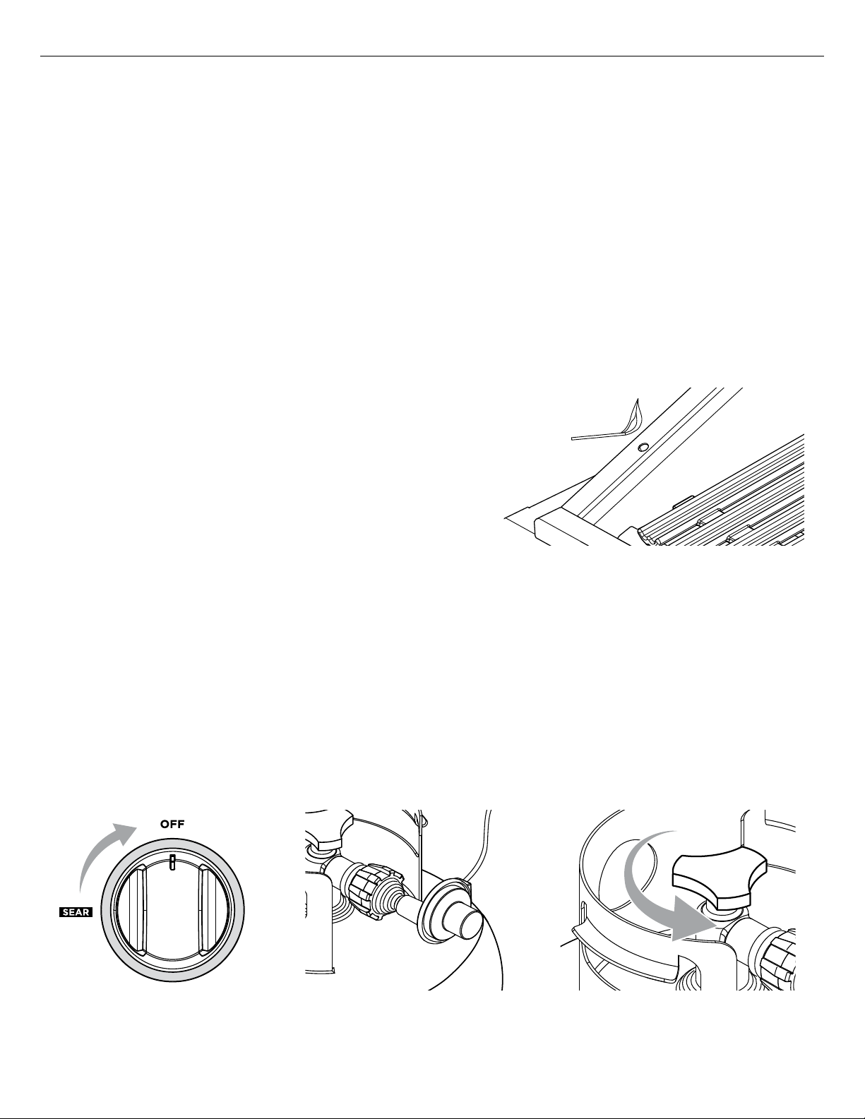
LP cart hook-up
Grills orificed for use with LP gas come equipped with a high capacity hose/regulator assem bly for
connection to a standard 20 lb. LP cylinder (Type 1). The LP tank is not included.
leak tested, do not remove the Regulator/Hose assembly from the grill during cart installation.
Connection: LP Hose with a Type 1 quick disconnect and regulator is included. Operating pressure:
11.0”W.C. Note: all gas piping and connectors must conform to the Standard for Connectors for
Outdoor Gas Appliances and Manufactured Homes, ANSI Z21.75/CSA 6.27.
To connect the LP regulator/hose assembly to the tank/valve assembly, first make sure the main
valve on the tank is completely closed. Although the flow of gas is stopped when the Type 1 system
is disconnected as part of its safety feature, you should always turn off the LP tank main valve (Fig.
08) after each use and during transport of the tank or unit. Insert the regulator inlet into the tank
valve and turn to the black coupler clockwise until the coupler tightens up. Do not over tighten
the coupler. Turn the main tank valve on and turn the burner control valves on the unit to the “HI”
position for about 20 seconds to allow the air in the system to purge. Turn valves off and wait five
minutes before attempting to ignite the burners.
To disconnect the coupler, first make sure the main tank valve is turned off. Grasp the coupler and
turn counter clockwise. The inlet will then disengage. Remove the inlet from the tank valve opening
if it has not already done so when it disengaged. Your local LP filling station should be equipped
with the proper equipment to fill your tank.
The grill system is
IMPORTANT!
Bottom of unit
Type 1 Regulator
Main Tank Valve
20 lb.
LP Tank
FIG. 08 LP Gas - Cart
Elbow 45°
1/2” female
NPT x 3/8” male flare
(installed on the unit)
LP Regulator hose
assembly 11" W.C.
*Installation must conform
with local codes or with the
National Fuel Gas Code ANSI
Z223.1 or the CSA-B149.2
Propane Installation Code
LP tank requirements:
A dented or rusty LP tank may be hazardous and should be checked by your LP supplier. The
cylinder that is used must have a collar to protect the cylinder valve. Never use a cylinder with
a damaged valve. Always check for leaks after every LP tank change. The LP gas cylinder must
be constructed and marked in accordance with the specifications for LP gas cylinders of the U.S.
Department of Transportation
(DOT or CAN/CSA-B339)
only. Do not change the regulator/hose assembly from that supplied with the unit or attempt to
use a Type 1 equipped regulator/hose assembly with a standard 510 POL tank/valve assembly. The
cylinder must be provided with a shut-off valve terminating in an LP gas supply cylinder valve outlet
specified, as applicable, for connection Type 1. If the appliance is stored indoors, the cylinder must
be disconnected and removed from the appliance. Cylinders must be stored outdoors in a wellventilated area out of the reach of children.
16
y Before connecting LP tank to regulator, check
that all grill burners and rotisserie valves are in
the OFF position and open grill hood.
y Do not place the Grill directly on the ground or
any other flat surface without support. This will
prevent damaging the regulator/hose assembly
by the weight of the grill.
y Check the hose, regulator and connectors for
damage. Look for cracks, abrasions, brittleness,
holes, dents and nicks.
y Do not attempt to remove, repair, or replace the
regulator/hose assembly by yourself. It must be
done by a qualified licensed technician only.
and designed for use with a Type 1 system
Page 19
INSTALLATION
Gas Hook-up
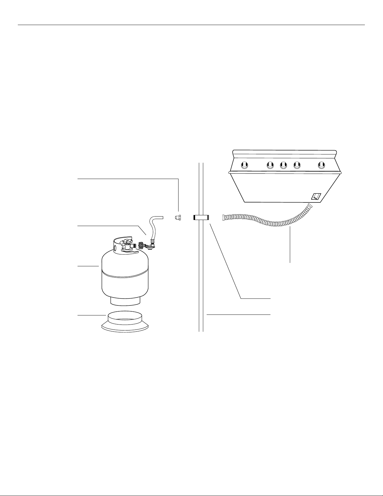
LP built-in hook-up
If the grill is to be installed in a built-in application, then the grill must be installed in accordance with
the built–in installation guidelines and
product
.
Connection: LP Hose with a Type 1 quick disconnect and regulator is included. Operating pressure:
11.0”W.C. All gas piping and connectors must conform to the Standard for Connectors for Outdoor
Gas Appliances and Manufactured Homes, ANSI Z21.75/CSA 6.27.
If you intend to operate your built-in grill on LP gas utilizing a 20v lb type 1 cylinder, then a builtin LP tank restraint must be installed prior to initial use of the grill. The Installer must supply ½” ID
Flex hose and fixed pipe and a flare adaptor as indicated in Fig. 09.
Adapter 3/8”
flare fitting
1/2” NPT female
(not supplied)
the LP regulator/hose assembly must be removed from the
Bottom of unit
EN
LP regulator/
hose assembly
20 lb
LP Tank
(not supplied)
Tank retention
device (not
supplied)
Note:
when an LP unit is being directly connected to an LP house system, you must follow the natural
FIG. 09 LP Gas - Built-in
1/2” ID flex hose with
1/2” NPT fittings
(not supplied)
1/2” NPT fixed pipe
(not supplied)
Enclosure wall
gas hook up guidelines.
The installer must provide the proper gas regulator to reduce the gas pressure to 11” W.C.
IMPORTANT!
Gas piping and connectors must be clamped within the the enclosure to avoid contact with moving
parts and hot surfaces. Where the gas piping passes through an opening in the enclosure, the
piping must be protected for a distance of at least 2” (50mm) either side of the opening.
17
Page 20
INSTALLATION
Leak Testing
IMPORTANT!
Gas leak testing must be carried out by a qualified technician.
General
Regularly check the whole system for leaks, or immediately check if the smell of gas is detected.
Before Testing
Do not smoke while leak testing. Extinguish all open flames. Never leak test with an open flame.
Make a soap solution of one part liquid detergent and one part water. You will need a spray bottle,
brush, or rag to apply the solution to the fittings. For LP units, check with a full cylinder.
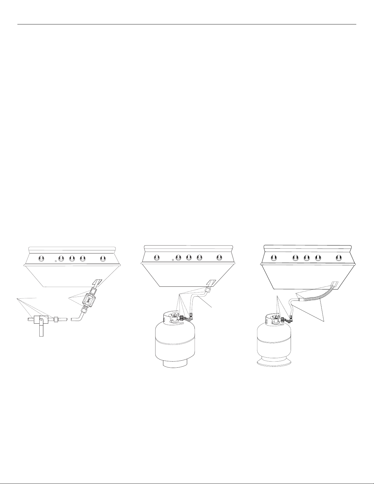
To Test
Make sure all control valves are in the “OFF” position. Turn the gas supply “ON”. Check all
connections from the supply line, or LP cylinder. Apply the soap solution around the connection,
tubing and end of the manifold. Soap bubbles will appear where a leak is present. If a leak is
present, immediately turn off gas supply, tighten any leaking connections, turn gas on, and recheck.
If you cannot stop a gas leak turn off the gas supply and call your local gas utility, or the dealer you
purchased the appliance from. Only those parts recommended by the manufacturer should be used
on the grill. Substitution can void the warranty.
IMPORTANT!
y Do not use the grill until all connections have been checked and do not leak.
y Check all gas supply fittings for leaks before each use. Keep a spray bottle of soapy water near the
gas supply shut-off valve. Spray all the fittings, bubbles indicate leaks
BOTTOM OF UNIT
LEAK TEST POINTS
LEAK TEST POINTS
BOTTOM OF UNIT
CHECK HOSES
FOR SIGNS OF
CRACKS, LEAKS
OR ABRASIONS
LEAK TEST POINTS
BOTTOM OF UNIT
CHECK HOSES
FOR SIGNS OF
CRACKS, LEAKS
OR ABRASIONS
18
FIG. 10 Nat. Gas
FIG. 11 LP Gas - cart FIG. 12 LP Gas - built-in
Page 21
INSTALLATION
Electrical Connection
IMPORTANT!
Use only a Ground Fault Interrupter (GFI) protected circuit with this grill.
General
Connection to AC Installation requires an outdoor 120VAC 15A GFI (Ground Fault Interrupter)
electrical outlet adjacent to the grill. The GFI outlet features an internal breaker that reduces shock
hazard. This type of outlet should be installed by a qualified electrician either inside the island
enclosure for built-in units, or near the location where a free-standing unit will be used. For built-in
grills, the supplied 12V transformer is connected to the grill during installation.
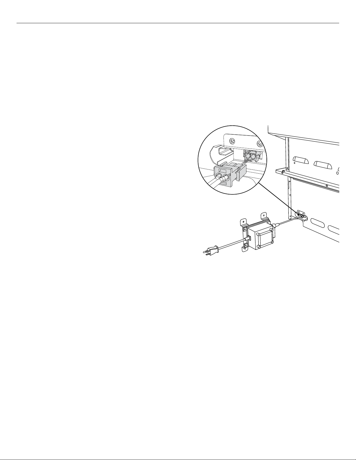
All grill models have a power transformer for the
ignition and internal lighting, which is concealed
in a box with an attached power supply cord. This
transformer must be secured in a dry location
and away from the grill firebox and excessive heat
area. When installing, it is recommended that the
transformer be located below the grill in a readily
accessible location. Be sure to provide adequate
access to facilitate service if the transformer or
connections should need future maintenance.
EN
If the electrical system fails to operate, a connection
may have come loose in shipping or the GFI may have
tripped, requiring a reset. See the Troubleshooting
section for more details.
IMPORTANT!
To protect against electrical shock, do not immerse
any power cords or plugs in water or any other liquid.
FIG. 13 Transformer Install Location
19
Page 22
INSTALLATION
Burner Adjustment
IMPORTANT!
Before lighting, inspect the gas supply piping or hose prior to turning the gas “on”. If there is evidence
of cuts, wear, or abrasion, it must be replaced prior to use.
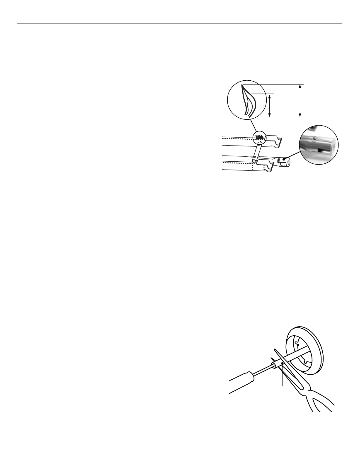
Grill burner air adjustment
Each grill burner is tested and adjusted at the factory prior
to shipment; however, variations in the local gas supply or a
conversion from one gas to another may make it necessary
to adjust the burners. The flames of the burners (except the
rotisserie burner) should be visually checked and compared
to that of the drawing in Fig.14. Flames should be blue and
stable with no yellow tips (LP units may have some yellow
tipping), excessive noise or lifting. If any of these conditions
exist, check if the air shutter or burner ports are blocked by
dirt, debris, spider webs, etc. If cleaning the burner ports
and air shutter does not improve performance, you can alter
the air shutter adjustment. The amount of air which enters a
burner is governed by a metal cup at the inlet of the burner
called an air shutter. It is locked in place by a screw which
must be loosened prior to lighting the burner for adjustment.
⅜ "
(10mm)
FIG. 14
1 ½ "
(38mm)
Grill burner flame height
Before beginning, ensure the grill is OFF and cool. To access the grill burner air shutters, first
remove the grates and radiants from the firebox, then remove the grill burner using instructions
shown on page 41. With a screw driver, loosen the lock screw on the face of the air shutter slightly
so that the air shutter can be adjusted.
To adjust
1 Be careful as the burner may be very hot.
2 If the flame is yellow, indicating insufficient air, turn the air shutter counter-clockwise to allow more air
to the burner.
3 If the flame is noisy and tends to lift away from the burner, indicating too much air, turn the air shutter
clockwise.
Note: reinstall the U-burner, ensuring the burner is level. Light the burner and check the flame. If
the color of the flame is blue and the height is stable, remove the burner and tighten the air shutter
screw. If the flames show instability or an inconsistent color, repeat the above procedure to readjust
the air shutter.
Low flame setting adjustment
The valves on the grill feature an adjustable low setting. Due to
fluctuations in gas pressure, heating value or gas conversion, you
BEZEL
may feel it necessary to increase or decrease gas flow in the low
position. We do not recommend adjusting the infrared rotisserie
burner.
To adjust
1 Light the burner.
2 Turn the control knob to the lowest setting (counter-clockwise).
3 Remove the knob.
4 While holding the valve shaft with pliers, insert a thin, flat tipped
screwdriver into the shaft and while viewing the burner adjust to a
minimum stable flame.
20
VALVE STEM
FIG. 15
Page 23
INSTALLATION
Radiant Assembly
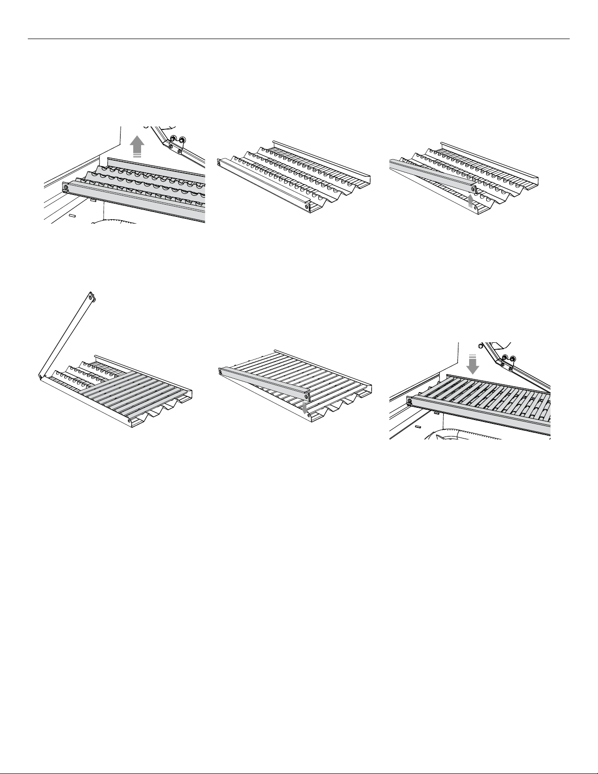
IMPORTANT!
Before assembling the radiant, check that the radiant trays have not moved during transit. They
should sit securely on their locating pins in the base of the grill.
2
1
Locate the radiant in the unit.
Unpack ceramic rods and remove
radiant from the unit
.
3
Unlock radiant end cap by
pushing it up with two fingers.
EN
5
4
Place the 18 ceramic rods onto
the radiant.
If a ceramic rod breaks
1
Unlock radiant end cap by pushing it up with two fingers.
2
Replace broken ceramic rod.
3
Lock radiant end cap.
To order a replacement ceramic rod, please visit www.dcsappliances.com
Lock radiant end cap.
6
Place the assembled radiant
into the unit.
21
Page 24
Installer Checklist
INSTALLATION
Specified clearances
maintained to
combustibles
Verified proper enclosure
ventilation
All internal packaging
and any adhesive residue
removed. To remove
stubborn residue, use
rubbing alcohol or a
commercially available
adhesive remover
Removed shipping bracket
Knobs turn freely, bezels
centered
Halo lighting is functioning
correctly
Each burner lights
satisfactorily - individually
or with adjacent burner lit
Air shutters adjusted
Low flame setting
satisfactory
Drip pan in place properly
and sliding freely
Pressure regulator
connected and set for 4.0”
C.E. Natural, 11.0” C.E. LP
gas
Manual shut-off valve
installed and accessible
Unit tested and free of
leaks
User informed of gas
supply shut-off valve
location
All radiant trays are
assembled and put in place
Check match lighting
Internal lighting is
functioning correctly
Transformer is tidy and
mounted securely, in a
suitable location
Please leave these
instructions with the user.
User, please retain these
instructions for future
reference.
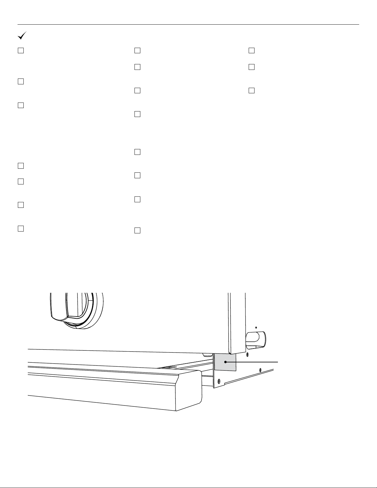
Contact DCS at www.dcsappliances.com if any of the listed items are missing. Please be prepared
with your Model #, Serial # and description of item(s) that are missing.
Tag location of
Model # and Serial #
IMPORTANT!
Read all installation instructions in this manual to see if the unit has been correctly installed. Ensure
that installation has been completed correctly before use.
22
Page 25

EN
Page 26
USING THE GRILL
Lighting Instructions
Grill lighting instructions
IMPORTANT!
Open the grill hood before lighting. Turn all knobs to “OFF”. Turn the main gas supply on. If you smell
gas, shut-off gas supply and call for customer care.
Pushing in on the burner knob will activate the Grill Igniter, and then turning the knob from the “OFF”
position will allow the flow of gas to the burner.
The Grill Igniter will glow orange, but there will be no clicking sound during ignition.
selected burner knob for two seconds. Verify that the hot surface igniter is glowing. Turn the burner
knob to "SEAR" position. Release the knob when the burner lights. If burner does not light in four to
five sec onds, turn knob "OFF" and wait five minutes before trying again so any ac cumulated gas may
dissipate.
Push in and hold the
IMPORTANT!
Only light one burner at a time.
Grill match lighting
If the burner will not light after several attempts, then
the burner can be match lit. If you have attempted to
light the burner with the ignition, allow five minutes for
any accumulated gas to dissipate. Keep your face as far
away from the outdoor appliance as possible and hold
a paper book match over the hole located on the top
left for burner on the left, or the right hole for the right
burner (Fig. 16). Push and turn the control knob which
is centered on the burner where the lit match is located,
to “SEAR”. If the burner does not light in four to five
seconds, turn knob off, wait five minutes and try again.
Improper lighting procedures can cause the LP tank flow control to activate resulting in reduced heat
output. If this is suspected the flow control will need to be reset.
See the Quick Start Guide for how to use the griddle and Infrared Hybrid Burner.
FIG. 16
Refer to the Troubleshooting section of the user guide if you encounter any difficulties lighting your grill.
Resetting the flow control
IMPORTANT!
Failure to follow the steps in the order shown may cause the Flow Limiting Device to activate resulting
in extremely low gas flow and irregular operation
1 All knobs must be in the
OFF position.
2 Attach regulator hose
assembly to the tank.
3 Open the LP tank valve.
(Two full turns min).
24
Page 27
USING THE GRILL
Grilling
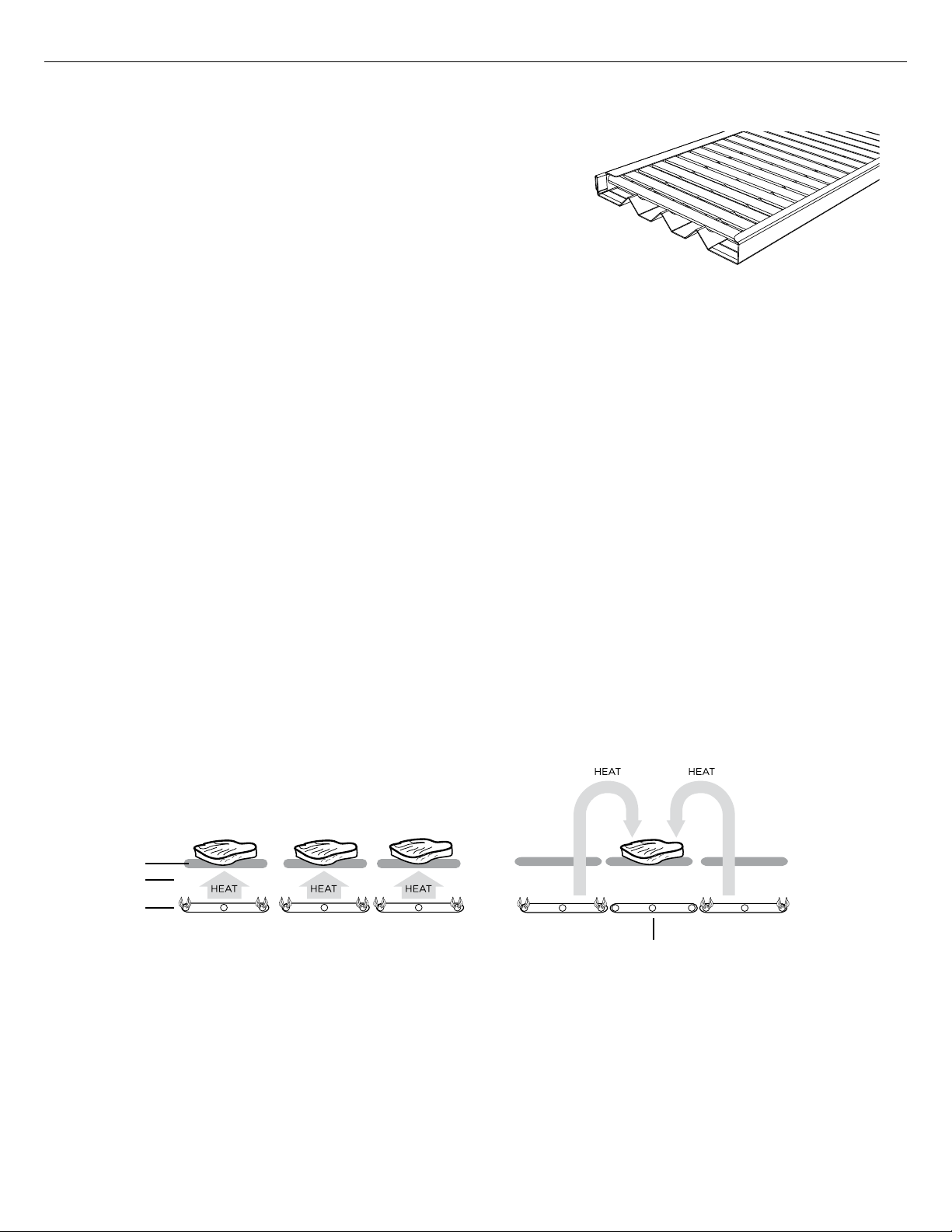
Grill
Each grill section consists of a large stainless steel burner,
stainless steel heat baffles, a series of ceramic rods encased
in a stainless steel radiant, and a stainless steel heat retaining
grate. Each burner is rated at
Below the burners there is a stainless steel heat baffle which
reflects usable heat upward into the cooking area and reduces
temperatures of the drip pan below. Above the burners are
stainless steel radiants which encase the ceramic rods and
protect the grill burner ports from blockage (Fig. 17).
The grill is supplied with radiant ceramic rods. Because of the porosity of ceramic rods, performance
is superior in the rods’ ability to capture heat as it rises from the grill burners. They also possess the
thermal mass needed for even cooking performance. Flare ups are controlled because the radiant
ceramic rods keeps grease from getting to the flames and igniting. The intense heat produced by
this system produces true grilled flavor as fats and juices are brought to the surface of the food and
caramelized. Discoloration of the grates is normal after use.
Direct/indirect cooking notes
Direct cooking involves placing food on grates over lighted burners. Use this method for foods that
take less than 20 minutes to cook or to sear larger items at the start of the cooking process that
will then be indirectly cooked to finish. Place items on the preheated surface and leave until they
no longer stick. Never spray water on the grill or into grease. The patented Grease Management
System™ reduces flare-ups by channeling grease away from the flame. Use a meat thermometer to
achieve desired doneness and remove items one degree below how you would like to enjoy them, as
the resting period before carving or consuming will raise the temperature.
25,000 Btu/hr or 26,5MJ/h.
FIG. 17
EN
Indirect cooking method is a popular alternative to direct heat grilling. Indirect cooking uses heat
from an adjacent heat source to cook food and, in many cases, reduces the possibility of overcooked
or overly browned food. Foods most appropriate for indirect grilling included breads, thicker pieces
of chicken or steaks. Indirect cooking involves placing the food to the side of or above the heat
source instead of directly over the flame and then closing the grill top to create an oven effect. All
the items you usually oven-roast can be grilled to perfection using indirect heating. Preheat the
burners surrounding the food to be cooked. Use your secondary cooking tray to hold food and add
water or chicken broth to the tray to prevent the natural juices from burning or evaporating.
Direct Heat Grilling Indirect Heat Grilling
FOOD
GRILL RACK
BURNER
BURNER OFF
IMPORTANT!
y Season your grates before first use and then periodically to protect the grate surface from corrosion,
and to stop food sticking. See 'Care and Maintenance'. To season the grates, pour a tablespoon of
vegetable oil on a soft cloth and rub on both sides of the grates. Only a light coating is needed and
some smoke may be visible during the preheating.
y Grilling requires high heat for searing and proper browning. Most foods are cooked at the “MEDIUM”
to “LOW” heat setting for the entire cooking time. However, when grilling large pieces of meat or
poultry, it may be necessary to turn the heat to a lower setting after the initial browning. This cooks
the food through without burning the outside. Foods cooked for a long time or basted with a sugary
marinade may need a lower heat setting near the end of the cooking time.
25
Page 28
USING THE GRILL
Grilling
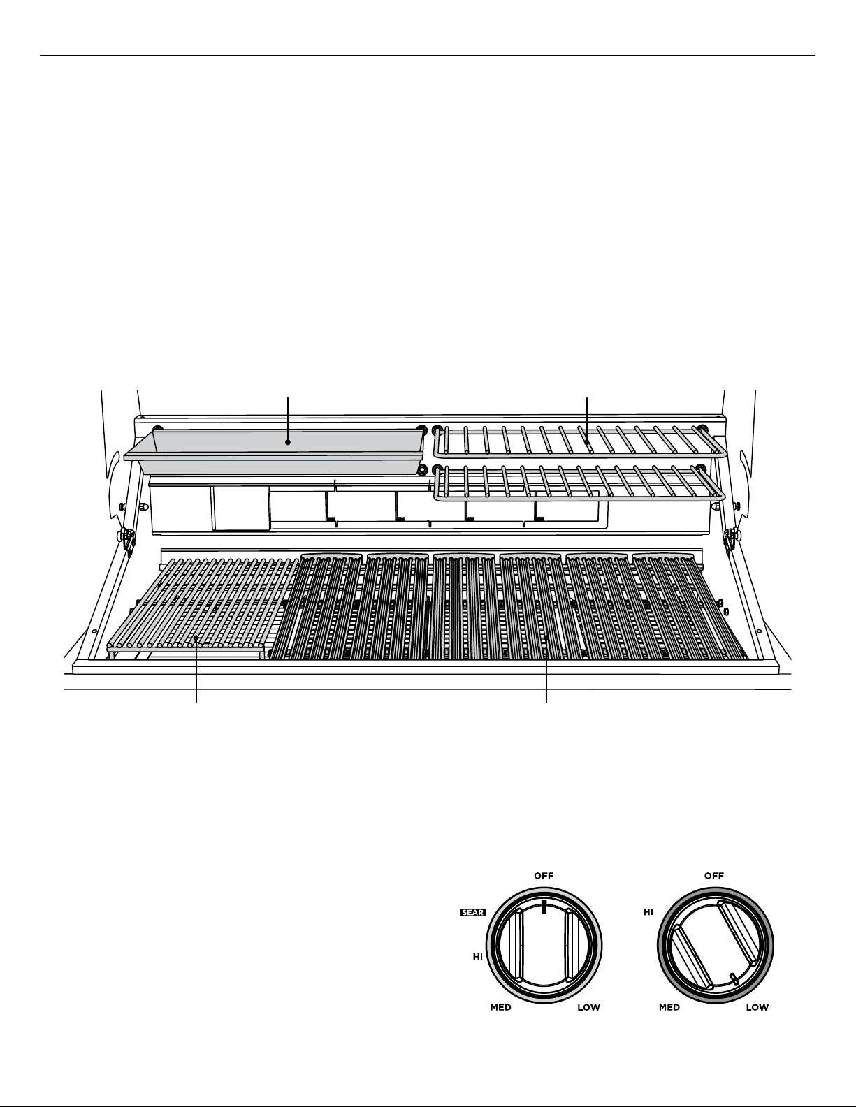
Secondary cooking
Two racks and one tray have been provided for secondary cooking. These can be utilized for
warming, smoking, roasting or slow-cooking food. Before using the secondary cooking surfaces with
the grill hood down, ensure that the height and width of food or cooking pans is not excessive. When
closing the hood there is a chance that food or cooking pans may be dislodged if these items are too
big. 20lbs is the maximum weight of food that should be placed in the secondary cooking area.
The secondary cooking racks and tray can be placed in four possible positions. When inserting the
racks and trays above the grill, they will click into place.
Note: all trays and racks are dishwasher safe.
IMPORTANT!
Do not use the rotisserie burner when the secondary cooking racks or trays are in place. Before using
the rotisserie burner, ensure that these racks and trays are removed.
SECONDARY COOKING RACKSSECONDARY COOKING TRAY
WIRE GRATE
Internal lighting
To add to the convenience of your grilling
experience, the grill has internal lighting set
inside the grill hood. This helps to help illuminate
the cooking surface in low light. To turn on the
lighting, push the LIGHT button on the lefthand side on the control panel. To turn it off,
press the button again. For guidance on how to
replace the light bulbs, please see the care and
maintenance section. Replacement light bulbs
are not covered by warranty.
Halo lighting
As an added feature, the grill is fitted with halo
lighting. When the grill is switched on, the halo
will turn white (Fig. 19), when a knob is turned
away from the ‘OFF’ position, the halo will turn
orange (Fig. 20).
26
DUAL-SIDED GRATES
FIG. 18
FIG. 19 White Halo FIG. 20 Orange Halo
Page 29
USING THE GRILL
Grilling
1 Ensure that the drip pan and grease tray are in place.
2 Light the grill burners following the lighting instructions.
3 Once you have verified the burners are lit, put the hood down to preheat for five to 10 minutes.
4 Place the food on the grill and cook to the desired doneness. Adjust heat setting, if necessary. The
control knob may be set to any position between “SEAR” and “LOW"
5 When you have finished using the grill, turn the control knobs to “OFF” and shut off the main gas supply.
6 Allow the grill to cool and clean the grates, drip pan and grease tray after each use.
EN
Note:
if using LP gas, your preheat time may be shorter than recommended. To prevent overcooking or
burning, you may want to lower the heat settings.
Using the temperature gauge
When preheating the grill, use the temperature gauge in the hood to check if the grill has reached
the desired heat setting.
Note: the temperature gauge only indicates air temperature inside the grill. For food safety and
optimal cooking performance, use a meat probe to check the temperature of meat while cooking and
to ensure desired internal temperatures are reached.
Wire grate
Designed to be used in conjunction with the charcoal insert, the wire grate fits on top of the insert to
provide the perfect surface for smoking your food. Smoke meat straight on the grate for an intense
flavour or use the grate to hold a tray of water under the meat to help even out the temperature and
keep the meat moist. If you do not wish to use the charcoal insert, the wire grate is still excellent for
normal grilling.
Note: the grate can only be used in a flat position (see page 32).
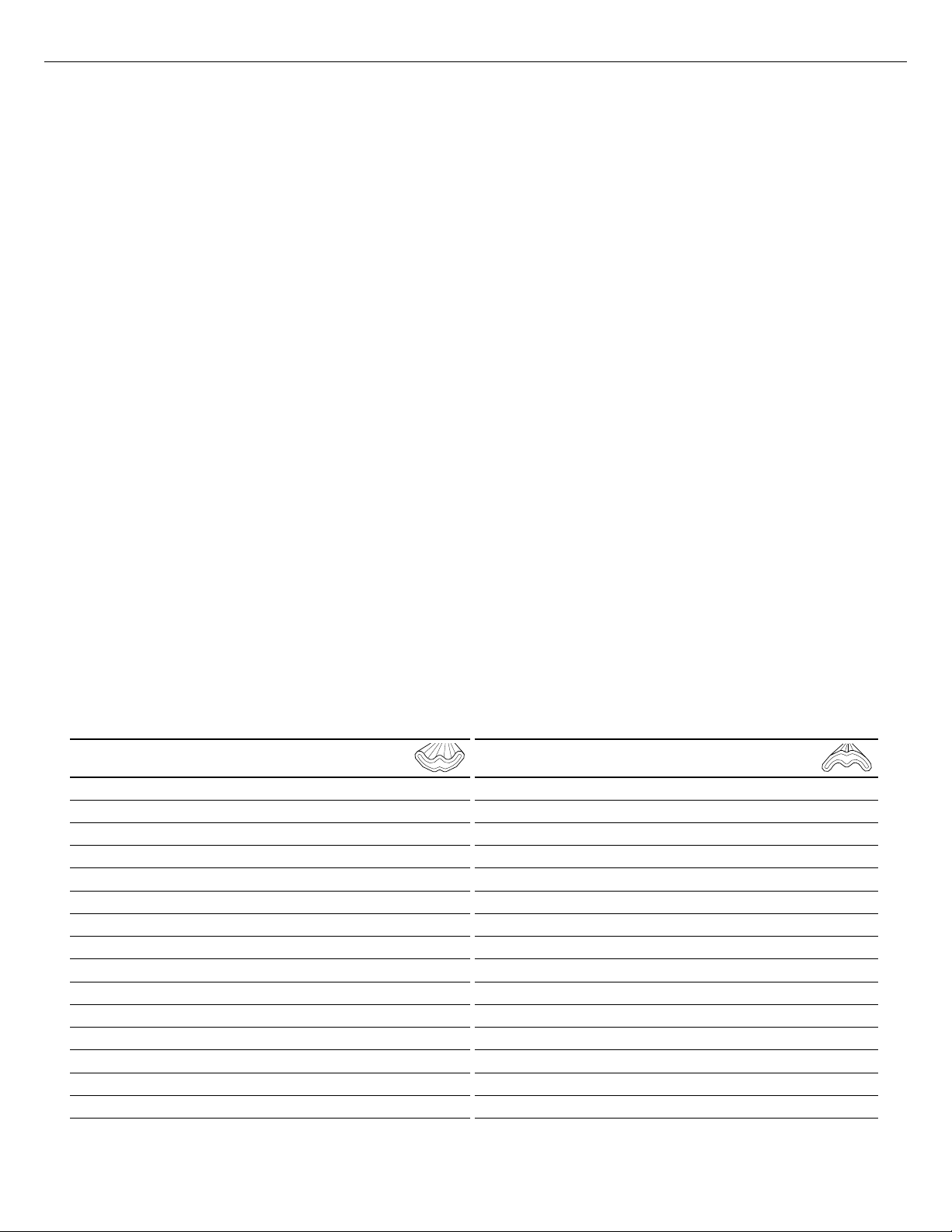
Dual-sided grates
Whether you or your guests crave seafood, steak or veggies, the double-sided grates provide varying
surfaces for varying textures. The “W”-shaped side creates nice sear lines for steaks, chicken and
chops and routes oil and grease away from the food. The opposite “radius” side offers more surface
area for support and handling of delicate items like scallops. (See below for a sample list of which
foods to cook on which side of the grate.)
"W" SHAPED GRATE RADIUS GRATE
y Chicken (bone-in and boneless cuts)
y Steaks
y Chops
y Burgers
y Ribs
y Kabobs
y Steak cuts of fish like tuna and swordfish
y Whole fish
y Game
y Oysters
y Large slices of whole vegetables
y Fruit
y Bread
y Sausages
y Hot dogs
y Delicate fish fillets
y Lobster meat
y Shrimp
y Scallops
y Clams
y Mussels
y Suckling pig
y Turkey legs
y Indirect cooking and smoking
y Potatoes
y Smaller vegetables or slices
y Roasted peppers
y Roasted whole garlic
y Pizza dough and flat breads
y Crab cakes
27
Page 30

USING THE GRILL
Grilling hints
The doneness of meat, whether rare, medium or well done, can depend on the thickness of the
cut. The cooking time of meat is dependent on the kind of meat, size, shape and cut along with
the temperature of the meat when cooking begins. Expert chefs say it is impossible to have a rare
doneness with a thin cut of meat. When defrosting meats, it is recommended to defrost overnight
in a refrigerator as opposed to a microwave. This will ensure meat retains it juices. Use a spatula
instead of tongs or a fork to turn the meat, as a spatula will not puncture the meat and let the juices
run out. To get the juiciest meats, add seasoning or salt after the cooking is finished and turn the
meat only once (juices are lost when the meat is turned several times). Turn the meat just after the
juices begin to bubble to the surface. Trim any excess fat from the meat before cooking. To prevent
steaks or chops from curling during cooking, slit the fat around the edges at two-inch intervals.
The cuts, temperatures, weights and grilling times in the following charts are meant to serve as a
guideline. Environmental factors such as wind, outside temperature and altitude can affect cooking
times, so should be taken into consideration. The USDA's definition of medium doneness is used
for the cooking times of beef and lamb, unless otherwise stated. Before carving, let roasts and
other large cuts of meat (including thick steaks) rest for 5 to 10 minutes after cooking. The internal
temperature will increase slightly during this time.
For indirect cooking, we suggest placing the meat in the secondary cooking area in the lower or
upper position depending on size and desired temperature.
Cooking Chart - Main Grill and Charcoal Insert
BEEF:
FOOD TYPE THICKNESS WEIGHT METHOD
New York
Strip
Steak
Ground Beef Patty 5 oz Direct Medium Heat 8-10 min
Fajitas 3/4" Thick 3 lb Direct Medium Heat 20 min
Finger Rib 2 lb Direct/Indirect Medium Heat 1-2 hours
Brisket 3-5 lb Direct/Indirect Low Heat 2-3 hours
LAMB:
FOOD TYPE THICKNESS WEIGHT METHOD
Chop 1" Thick Direct High Heat 6-8 min
Leg of Lamb Roast 3-7 lb Direct/Indirect Low 2-3 hours
Rack of Lamb 1-2 lb Direct/Indirect Medium Heat 15-20 min
Porterhouse 1" Thick Direct High Heat 6-8 min
Rib-Eye 1" Thick Direct High Heat 6-8 min
T-Bone 1" Thick Direct High Heat 6-8 min
1" Thick Direct High Heat 6-8 min
TEMP CONTROL
DIAL
TEMP CONTROL
DIAL
APPROX TIME
(HRS/MINS)
APPROX TIME
(HRS/MINS)
PORK:
FOOD TYPE THICKNESS WEIGHT METHOD
Hot Dog 2-4 oz Direct/Indirect Medium Heat 5 min
Bratwurst 4 oz Link Direct/Indirect Medium Heat 10-15 min
Ribs: Baby Back 3-5 lb Direct/Indirect Low Heat 3-4 hours
Spare Ribs 3-5 lb Direct/Indirect Low Heat 4-6 hours
Boston Butt/Shoulder 3-7 lb Direct/Indirect Low Heat 4-6 hours
TEMP CONTROL
DIAL
28
APPROX TIME
(HRS/MINS)
Page 31

USING THE GRILL
Grilling
Cooking Chart - Main Grill and Charcoal Insert
POULTRY:
FOOD TYPE THICKNESS WEIGHT METHOD
Chicken Breast Boneless 6 -7 oz Direct/Indirect Medium Heat 10-12 min
Chicken Thigh Boneless 3-5 oz Direct/Indirect Medium Heat 10-12 min
Chicken Whole 3-5 lb Indirect/Rotisserie Medium Heat 1-2 hours
Duck Whole 3-5 lb Indirect/Rotisserie Medium Heat 1-2 hours
Turkey Whole 10-12 lb Indirect/Rotisserie Medium Heat 2-3 hours
SEAFOOD:
FOOD TYPE THICKNESS WEIGHT METHOD
Halibut ½ -1" Thick Direct Medium-High Heat 6-10 min
Snapper ½ -1" Thick Direct Medium-High Heat 6-10 min
Salmon ½ -1" Thick Direct Medium-High Heat 6-10 min
Fish Fillet/Steak:
Shrimp 2-4 oz Direct Medium-High Heat 4-5 min
Fish Whole 3-5 lb Indirect Low-Medium Heat 20-30 min
Sea Bass ½ -1" Thick Direct Medium-High Heat 6-10 min
Swordfish ½ -1" Thick Direct Medium-High Heat 6-10 min
Tuna ½ -1" Thick Direct Medium-High Heat 6-10 min
Trout ½ -1" Thick Direct Medium-High Heat 6-10 min
TEMP CONTROL
DIAL
TEMP CONTROL
DIAL
APPROX TIME
(HRS/MINS)
APPROX TIME
(HRS/MINS)
EN
VEGETABLES:
FOOD TYPE THICKNESS WEIGHT METHOD
Aubergine 1" Thick Slices Direct Low-Medium Heat 4-6 min
Asparagus ½" Stem
Diameter
Corn on the Cob Whole Direct/Indirect Low-Medium Heat 20-25 min
Mushroom - Portobello Whole Direct Low-Medium Heat 8-10 min
Onion ½" Thick Slices Direct Low-Medium Heat 10-12 min
Peppers Halved Direct Low-Medium Heat 8-10 min
Potato ½" Thick Slices Direct Low-Medium Heat 10-15 min
Tomato Halved Direct Low-Medium Heat 4-6 min
Zucchini
Sweet Potato
FRUIT:
FOOD TYPE THICKNESS WEIGHT METHOD
Bananas Halved Direct Low-Medium Heat 5-6 min
Peaches
Apricots Halved Direct Low-Medium Heat 6-8 min
Nectarines Halved Direct Low-Medium Heat
Pineapple ½" Thick Slices Direct Low-Medium Heat
1" Thick Slices Direct Low-Medium Heat
1" Thick Slices Direct Low-Medium Heat
Halved
Direct Low-Medium Heat 4-6 min
Direct Low-Medium Heat 6-8 min
TEMP CONTROL
DIAL
TEMP CONTROL
DIAL
APPROX TIME
(HRS/MINS)
4-6 min
10-12 min
APPROX TIME
(HRS/MINS)
6-8 min
5-6 min
* Slow cooking of some meat cuts may require surfaces to be seared over direct high heat prior to indirect cooking.
29
Page 32

USING THE GRILL
Grilling
Cooking Chart - Smoking
BEEF:
FOOD TYPE THICKNESS WEIGHT METHOD
Brisket 4-6 lb Indirect Low Heat 6-8 hours
LAMB:
FOOD TYPE THICKNESS WEIGHT METHOD
Leg of Lamb Roast 3-7 lb Direct/Indirect Low Heat 2-3 hours
PORK:
FOOD TYPE THICKNESS WEIGHT METHOD
Ribs: Baby Back 3-5 lb Indirect Low Heat 4-5 hours
Spare Ribs 3-5 lb Indirect Low Heat 5-6 hours
Boston Butt/Shoulder 3-7 lb Indirect Low Heat 6-8 hours
TEMP CONTROL
DIAL
TEMP CONTROL
DIAL
TEMP CONTROL
DIAL
APPROX TIME
(HRS/MINS)
APPROX TIME
(HRS/MINS)
APPROX TIME
(HRS/MINS)
POULTRY:
FOOD TYPE THICKNESS WEIGHT METHOD
Chicken Whole 3-5 lb Indirect Low Heat 2-4 hours
Duck Whole 3-5 lb Indirect Low Heat 2-4 hours
Turkey Whole 10-12 lb Indirect Low Heat 8-10 hours
SEAFOOD:
FOOD TYPE THICKNESS WEIGHT METHOD
Salmon ½ -1" Thick Indirect Low Heat 1 hour
Swordfish ½ -1" Thick Indirect Low Heat 1 hour
Fish Fillet/Steak:
Shrimp 2-4 oz Indirect Low Heat 1 hour
Fish Whole 3-5 lb Indirect Low Heat 3-4 hours
VEGETABLES:
FOOD TYPE THICKNESS WEIGHT METHOD
Aubergine 1" Thick Slices Indirect
Corn on the Cob Whole Indirect
Mushroom - Portobello Whole Indirect
Onion Whole/halved Indirect
Peppers Whole/halved Indirect
Potato Whole/halved Indirect
Tomato Whole/halved Indirect
Zucchini
Sweet Potato
Tuna ½ -1" Thick Indirect Low Heat 1 hour
Trout ½ -1" Thick Indirect Low Heat 1 hour
Mackerel ½ -1" Thick Indirect Low Heat 1 hour
Halved
lengthwise
Whole/halved Indirect
Indirect
TEMP CONTROL
DIAL
TEMP CONTROL
DIAL
TEMP CONTROL
DIAL
Low Heat
Low Heat
Low Heat
Low Heat
Low Heat
Low Heat
Low Heat
Low Heat
Low Heat
APPROX TIME
(HRS/MINS)
APPROX TIME
(HRS/MINS)
APPROX TIME
(HRS/MINS)
1 hour
1 ½ hours
1 ½ hours
2 hours
1 ½ hours
2 hours
45 minutes
1 hour
2 hours
30
Page 33

USING THE GRILL
Grilling
Meat Temperatures
The “Remove” temperature on the left is the target temperature to remove from heat source. The “Ideal”
temperature on the right is the ideal internal temperature after resting. These temperatures are all Fahrenheit.Note, these are not USDA Recommendations. The USDA temperatures are conservatively 10
because of food safety however most professional chefs will not cook a medium-rare steak to 150
FOOD TYPE RARE MEDIUM-RARE MEDIUM MEDIUM-WELL
°
– 15° higher
°F
.
EN
REMOVE IDEAL REMOVE
Beef Steaks
Beef Roasts
Lamb Chops
Lamb Roast
Pork Chops
Pork Roasts
Veal Chops
Veal Roasts
FOOD TYPE RESTING TIME REMOVE IDEAL INTERNAL TEMPERATURE
Whole Chicken - Roasted 5 minutes
Whole Turkey - Roasted*
125° 130° 130° 135° 140° 145° 155° 160°
120° 125° 125° 130° 135° 145° 150° 160°
125° 130° 130° 135° 135° 145° 155° 160°
120° 130° 125° 130° 135° 145° 150° 160°
125° 130° 135° 140° 145° 150°
125° 130° 135° 140° 145° 150°
130° 135° 140° 145° 155° 160°
125° 130° 135° 145° 150° 160°
20-60 minutes 150° - 170°
IDEAL
160° - 165°
REMOVE IDEAL REMOVE
165°- 170°
165° - 170°
IDEAL
* A large Turkey can take 60 minutes of resting with a temperature shift of 20° or more
31
Page 34

USING THE GRILL
Grate positions
As well as moving the grates to be positioned to your preference along the grill, the dual-sided
grates can also be placed flat or in an angled position. If the grates are hot, please use the multitool to move the grates or re-position them. Placing the grates in an angled positioned (Fig. 21),
allows fat and grease to run off food and into the grease management system. It also allows for a
slightly slower cooking, than if the grate was placed flat (Fig. 22). If you are using a griddle plate
please ensure that the plate is flat or tilted at an upward angle, and not tilted down. Wire grates
can only be used in the flat position as shown in Fig. 23.
Dual-sided grates
FIG. 21
FIG. 22
Wire grates
FIG. 23
FIG. 24
Using the multi-tool:
The multi-tool is an accessory that comes included with the grill. This can be used to lift and move
grates, lift the charcoal burner lid and adjust the charcoal burner venting filters. It can be used to
scrape grease and fat residues into the hole which filters grease down into the drip pan.
To adjust grates using the multi-tool
1 Grip the multi-tool handle, with the flat-edged end
at the top.
2 Rotate the multi-tool 90 degrees and insert the flat-
edge end into the center grate slot, making sure the
end is below the middle horizontal bar of the grate.
Note: there is greater balance and control of the
grate when the multi-tool is centered.
3 Rotate the multi-tool back 90 degrees. The notches
in the flat-edged end will lock the grate into place.
4 Carefully lift the grate out of the grill or into your
desired position.
5 Rotate the multi-tool again to remove it from the
grate.
FIG. 25
IMPORTANT!
Take care when using the multi-tool to move the grates. The hot and heavy grates can cause injury.
32
Page 35

USING THE GRILL
Charcoal insert
IMPORTANT!
Do not use lighter-fluid in the charcoal insert or on the grill. The solid fuel will ignite from the
burners, it does not need to be lit by a match or butane lighter.
1 Place charcoal, woodchips or briquettes into the insert.
Be careful not to overload with solid fuel (one layer of
briquettes is recommended).
2 Remove the grates and ceramic rods. Place the charcoal
insert on top of the burner. The insert will clip onto barbs in
the frame of the grill.
3 Light the grill burners following the lighting instructions on
page 24. Turn the control knob to "SEAR".
4 Wait eight to 10 minutes, allow smoke to get to your desired
preference. The solid fuel should begin to grey around the
edges.
5 Shut off the burner, the solid fuel will continue to burn and
smoke.
6 When you have finished using the grill, turn the control
knobs to “OFF”.
7 Allow the grill to cool and clean the grates, drip pan and
grease tray after each use. The multi-tool can be used
to scrape out the bottom of the insert. See Care and
Maintenance on page 43 for more instructions on cleaning
the charcoal insert.
FIG. 26
EN
Adjusting the charcoal insert
The heat and burn rate of the charcoal insert can be controlled
by adjusting insert to reduce the level of oxygen supplied to
the fire and slow the cooking rate. Removing the lid provides
an excellent cooking surface for direct grilling. Note: the wire
grate must be used in conjunction with the charcoal insert for
direct grilling. There is also a venting adjustment on the top of
the insert lid, it is recommended that the vents are modified
prior to cooking. If the lid or vents have to be adjusted during
cooking, please use the multi-tool as the charcoal burner insert
will be hot.
Using wood and charcoal
y Wood should be soaked briefly in water beforehand
y Larger wood chunks burn slower than smaller chips, giving a longer smoking time
y Different wood types (and charcoal types) impart different flavours to the food
y Charcoal and wood can be added periodically to the tray as required to extend the cooking time
FIG. 27
IMPORTANT!
When using multiple grill accessories (e.g. charcoal insert, griddle plate etc), at least one of the
two center burners should remain accessory-free.
33
Page 36

USING THE ROTISSERIE
IMPORTANT!
When connecting your rotisserie motor, first connect the
motor to the grill and then plug the grill into the outlet.
General
The grill rotisserie system is designed to cook items
from the back using infrared heat. The location of the
burner allows the placement of the secondary cooking
tray beneath the food to collect juices and drippings for
basting and gravy. To flavor the contents of the cooking
tray, you can add herbs, onion, garlic, or spices. Hams are
especially good with the addition of pineapple slices and
brown sugar to the cooking tray. The rotisserie burner is
an infrared type which provides intense searing radiant
heat. Preferred by chefs over other methods, this intense
heat is magnificent for searing in the meat’s natural
juices and nutrient.
The orange/red glow will even out in about five minutes.
The rotisserie motor is equipped with metal gears and is
capable of turning a cut of meat or poultry that weighs
up to 50 lb. The rotisserie motor on the grills is secured
down to a cast rotisserie block with two black screwdown knobs. The rotisserie block is in turn bolted to the
side panel. The rotisserie rod is assembled into the motor
assembly by placing the pointed end into the motor, and
resting the handle end on the support at the left side
of the grill. With the rod pushed as far as possible into
the motor, the round end of the rod should rest on the
rollers.
FIG. 28
The motor is equipped with a halogen bulb to provide
light when other sources of light are not sufficient. Use
only a 50W (or its equivalent) Max. Halogen Narrow
Flood replacement bulb.
IMPORTANT!
Halogen lamps are constructed of a glass bulb with
a pressurized internal filament tube that operates at
high temperatures and could unexpectedly shatter.
Should the outer bulb break, particles of extremely
hot glass could be discharged into the fixture
enclosure and/or surrounding environment, thereby
creating a risk of personal injury or fire. When
replacing the bulb, let the bulb cool, and assure that
power to the light has been turned off. Never allow
the hot bulb to come into contact with water. DO
NOT TOUCH the light bulb when in use. It may be
hot enough to cause injury.
FIG. 29
FIG. 30
MOTOR
LIGHT
34
Page 37

USING THE ROTISSERIE
IMPORTANT!
Do not use the rotisserie burner when the secondary cooking racks or trays are in place. Before using
the rotisserie burner, ensure that these racks and trays are removed.
Preparation
Recommended: dental floss or butcher string, scissors, secondary cooking tray, pliers, meat probe,
foil, and hot pads.
Working area
Allow enough space to accommodate food and rotisserie rod assembly in a clean environment.
Meat preparation
Tie meat with butcher string or dental floss in three areas. Purchase a roast that is equally balanced
from top to bottom in size to ensure meat will cook evenly while on the Rotisserie. For Poultry, tie
wings and legs to the body using dental floss or butcher string to prevent flopping around while
turning.
EN
1 Determine the center placement for the food,
put first prong on the rod, turn ‘L’- shaped
screw to tighten.
3 Pick up the rod, rotate it to check for balance.
If unbalanced, adjust prongs and food. Take
pliers and tighten the ‘L’- shaped screws on
both prongs.
2 Center tied meat/poultry on the rod, place
second prong, turn ‘L’- shaped screw to
tighten.
4 Remove secondary cooking racks. To catch
meat drippings, place secondary cooking tray
onto grates or ceramic radiant rods depending
on your preference. Note: grates must first be
removed if placing tray on ceramic radiant rods.
35
Page 38

USING THE ROTISSERIE
To light the rotisserie burner before cooking
The location of the rotisserie burner makes it more susceptible to strong wind conditions, more so
than the protected grill burners. For this reason you should avoid operating the rotisserie during
windy conditions. As an added safety feature we’ve equipped the burner with an automatic safety
valve which will not allow gas to flow to the rotisserie burner unless the following conditions are
present with the knob on:
1 The safety valve button is pressed, and held down.
2 The safety valve thermocouple has been sufficientlyheated to keep safety valve open.
Note: the Grill Igniter will glow orange, but there will be no clicking sound during ignition.
Push in and hold the selected burner knob for two seconds. Verify that the hot surface igniter is
glowing. Turn the burner knob to “HI” position. Then press and hold the safety valve button in for 10
seconds or until the burner remains lit. Once lit, turn control knob to desired setting. If burner does
not light, turn knob "OFF" and wait five minutes before trying again so any accumulated gas may
dissipate.
y If relighting a hot burner, wait five minutes.
y Never leave the control knob on if rotisserie is not in use.
y Never light the grill burners under the rotisserie while the rear rotisserie burner is lit.
Manual lighting
To manually light the rotisserie, place a butane lighter
near the tip of the thermocouple. Push in and turn the
control knob to “HI”. Hold the safety valve button in for
10 seconds or until the burner remains lit. Once lit, turn
control knob to desired setting. If the burner does not
light, release the safety valve button and turn the control
knob to “OFF” and wait 5 minutes before trying again.
IMPORTANT!
Keep hands and face away from front of burner! Stand to
the side when lighting. Once lit move hand away quickly.
FIG. 31
IMPORTANT!
Electrical Grounding Instructions: this appliance (rotisserie motor) is equipped with a three-prong
(grounding) plug for your protection against shock hazard and should be plugged directly into
a properly grounded three-prong receptacle or a three-prong grounded extension cord rated for
the power of the rotisserie motor and approved for outdoor use with a W-A marking. Do not cut
or remove the grounding prong from this plug. Use only a ground fault interrupter (GFI) protected
circuit.
The rotisserie motor must be electrically grounded in accordance with local codes or, in the absence
of local codes, with the National Electrical Code, ANSI/NFPA 70. Keep the rotisserie motor electric
cord away from the heated surfaces of the grill. When not in use, remove and store the motor in a
dry location. To protect against electric shock, do not immerse the cord or plug in water or other
liquid. Unplug rotisserie unit from the outlet when not in use and before cleaning. Allow the rotisserie
to cool before putting on or taking off parts.
36
Page 39

Grilling
USING THE ROTISSERIE
EN
1 Place prepared rod into motor, lay across
and into the rollers on other side.
3 To check temperature of the meat, turn off
motor and turn temperature to low while
using a meat probe.
2 Once placement has been verified, ignite
burner and start rotisserie motor. Turn the
control knob to the desired setting.
4 Once finished, turn the motor and rotisserie
knob to “OFF”. If you have finished using the
appliance altogether, turn the main gas supply
off too.
5 Remove the rod and place meat or poultry on
pan then remove prongs. Take care as the rod
will be hot.
IMPORTANT!
The prongs are very sharp. Keep hands
away from tips when removing the food.
Note: cover with foil for a 15 to 20 minute
waiting time. Meat will carve better and
juices will go back into the meat.
37
Page 40

USING THE ROTISSERIE
Rotisserie rod storage
The rotisserie rod can be stored in the tray located under the grill head. When storing the rotisserie
rods, please use two hands to store it correctly and ensure it is locked into place. Please use two
hands to remove the rod from its storage compartment, taking care to ensure it does not drop.
FIG. 32 FIG. 33
Using the rod storage unit
1 Slide out the drip tray that sits underneath the control panel.
2 Locate hooks under front lip of the drip tray.
3 Place rotisserie rod onto hooks.
4 Slide the drip tray back into place.
38
Page 41

ACCESSORIES
The following accessories can be purchased separately from authorized DCS dealers.
Grill covers
To ensure high performance and longevity of your grill, we recommend purchasing a grill cover.
Particularly if your grill is going to be stored outside.
Storage unit
The unit can be bolted onto either side of the grill. Please note, if you are using the rotisserie, the
storage unit will need to be installed on the opposite side to where the motor sits. You can install
up to two storage units on the grill, however, as the storage unit is attached at the same location
as the rotisserie motor, installing two storage units will mean that the rotisserie motor cannot be
installed.
All removable parts of the storage unit are dishwasher safe. Please see the storage unit quick start
guide for install instructions, use and care and further information.
Griddle plate
The griddle plate can be purchased separately.Do not place griddle plates side-by-side. Please see
the griddle plate quick start guide for install instructions, use and care and further information.
Infrared hybrid burner
Provides an additional cooking option. Please see the IR burner quick start guide for install
instructions, use and care and further information.
EN
Insulated jacket
We recommend purchasing a DCS insulated jacket if installing your grill into a combustible
enclosure, as it will reduce the risk of fire, property damage and personal injury. Please see the
insulated jacket quick start guide for install instructions, use and care and further information.
39
Page 42

CARE AND MAINTENANCE
IMPORTANT!
Before each use, inspect the gas supply piping or hose prior to turning the gas “on”. If there is
evidence of cuts, wear, or abrasion, on the piping or hose it must be replaced prior to use.
Regulator and hose replacement
The pressure regulator and hose assembly supplied with the unit must be used. If replacements are
needed, contact customer care at www.dcsappliances.com. Do not use the grill if the odor of gas
is present. If the unit is LP, screw the regulator into the tank and leak check the hose and regulator
connections with a soap and water solution before operating the grill. Turn all knobs to “OFF” then
turn on the gas supply. If LP, check that there is gas in the tank.
IMPORTANT!
y Always keep your face and body as far away from the grill as possible when lighting.
y Do not leave the grill unattended while cooking.
y Keep a spray bottle of soapy water near the gas supply valve and check connections before each use.
y Do not attempt to light the grill if the odor of gas is present.
y Wait five minutes before relighting a hot grill.
Grill grates
Method 1
Turn U-burners on “HI” for 15-20 minutes to burn any remaining food particles. After turning the grill
“OFF”, use a bristle barbeque brush to remove any remaining food particles or ash.
Method 2
The easiest way to clean the grill is immediately after cooking is completed and after turning off the
flame. Wear a barbeque mitt to protect your hand from the heat and steam. Dip a soft brass bristle
barbeque brush in a mixture of two cups of tap water and ½ cup of vinegar and scrub the hot grill.
Dip the brush frequently in the bowl of water and vinegar. Steam, created as water contacts the hot
grill, assists the cleaning process by softening any food particles. The food particles will fall onto
the ceramic rods and burn or fall into the drip pan. If the grill is allowed to cool before cleaning, this
process will be more difficult.
Method 3
Take about one foot of aluminum foil, crumpled up in a ball and rub it over cooled grates to release
food particles.
Note:
grill grates must be re-seasoned after cleaning to prevent rust stains.
Drip pan and grease tray
The full width drip pan with grease tray will collect
grease from the grill section and boil overs and
spills from the side burners. Allow the pan and its
contents to cool before attempting to clean. Clean
grease from the pan often to avoid the possibility of
a grease fire.
Ceramic rods
It is not necessary to remove the ceramic rods for
cleaning. They burn themselves clean during the next
cooking operation. Periodically the trays holding the
ceramic rods need to be turned over, and shaken free
of debris for a thorough cleaning. How often you use
the grill and the amount and type of food cooked will
determine when it is necessary to clean the trays. If
grease can be seen on the top of the tubes or if there
are a lot of flare-ups during cooking, the tubes need
to be turned over and heated on “HI” for 30 minutes;
longer for heavy soil.
FIG. 34
40
Page 43

CARE AND MAINTENANCE
304 Stainless steel
The grill is made from non-rusting and non-magnetic stainless steel. After initial usage, areas of
the grill may discolor from the intense heat given off by the burners, this is normal. There are
many different stainless steel cleaners available. Always use the mildest cleaning procedure first,
scrubbing in the direction of the grain. To touch up noticeable scratches in the stainless steel, sand
very lightly with wet 100 grit emery paper in the direction of the grain. Specks of grease can gather
on the surfaces of the stainless steel and bake on to the surface and give the appearance of rust.
For removal use an abrasive pad (Scotch Brite is good) in conjunction with a stainless steel cleaner.
Always rub in the direction of the grain.
Note: stainless steel tends to corrode in presence of chlorides and sulfides especially in coastal areas.
To ensure corrosion prevention, wash all stainless steel surfaces every three to four weeks with fresh
water and stainless cleaner. Keep grill covered when not in use.
Removing the U-burners for cleaning
EN
1 Ensure gas supply has been turned off. Remove
the grill grates, then lift out the grill radiant
tray. Use a screw driver to pry open the slot to
release the u-burner.
1
Grip the u-burner and press downwards with
your thumbs on the bracket in the back while
lifting up on the u-burner. Pull it up and
slightly to the rear of the unit so the burner
air shutter head comes off the brass orifice
at the front, angle the burner sideways, and
remove.
IMPORTANT!
When re-installing the u-burner after cleaning, ensure that it is completely level and locked in place.
This is needed to ensure your grill provides an even cooking performance.
Grill burner cleaning
Clean the exterior of the burner with a stainless steel wire
brush. Clear stubborn scale with a metal scraper. Clear any
clogged ports with a straightened paper clip. Never use a
wooden toothpick as it may break off and clog the port.
Shake out any debris through the air shutter. Use a flashlight
to inspect the burner inlet to ensure it is not blocked. If
obstructions can be seen, use a metal wire coat hanger that
has been straightened (see Fig. 35).
Orifice cleaning
With the burner removed, remove the orifice and shine a
flashlight through the opening to ensure there is no blockage.
Use a needle to clear any debris. Be extremely careful not to
enlarge the hole or break off the needle.
FIG. 35
41
Page 44

CARE AND MAINTENANCE
Burner alignment
IMPORTANT!
Center the burner onto the orifice properly before lighting the grill to prevent fire hazard or explosion.
”
⁄
MIN
KNOB CONTROL
REMOVE DRIP PAN TO VIEW CONNECTION
Fig. 36 Fig. 37
VALV E
PANEL
VALV E
Be careful not to misalign the air shutters’ original position (unless readjusting). Lower the rear of
the burner into the cutouts on the support channel at the rear of the burner box. Make sure it is
level and does not rock. Light all of the burners and check that the flame is blue, stable and even.
If adjustments are necessary, refer to page 20. Complete these adjustments prior to cooking.
Replace internal lighting bulbs
Note: replacement bulbs are halogen, 12 volt, 10W max, T3 type
with a G4 bi-pin base.
1 Carefully remove the light bulb covers using your fingers or a
screwdriver.
2 Remove the light bulb and replace with a new bulb. Use gloves when
handling the
halogen bulbs as oils from finger-tips could damage the bulb.
3 Reinsert the light bulb cover. It should click back into place.
Cleaning light bulb covers
1 Carefully remove the light bulb covers using your fingers or a
screwdriver.
2 Clean the covers and remove grease with a cloth, warm water and
dishwashing liquid.
3 Reinsert the light bulb cover. It will click back into place.
BURNER
VENTURI
IMPORTANT!
Halogen lamps are constructed of a glass bulb with a pressurized internal filament tube that operates
at high temperatures and could unexpectedly shatter. Should the outer bulb break, particles of
extremely hot glass could be discharged into the fixture enclosure and/or surrounding environment,
thereby creating a risk of personal injury or fire. When replacing the bulb, let the bulb cool, and assure
that power to the light has been turned off. Never allow the hot bulb to come into contact with water.
DO NOT TOUCH the light bulb when in use. It may be hot enough to cause injury.
42
Page 45

CARE AND MAINTENANCE
Care of the multi-tool
y Wash the multi-tool with hot soapy water after each use.
y To protect the condition of the natural wood handle, do not store while wet or in direct sunlight.
IMPORTANT!
Take care when handling and cleaning the multi-tool, as it has sharp edges that could cause injury.
Cleaning the charcoal insert:
1 Once cooled, remove the charcoal insert from inside the grill and dispose of the ash safely.
2 Scrape off any possible food residue using the multi-tool.
3 Clean off the carbon deposit on the bottom of the insert using a bristle barbeque brush.
4 Wash the insert with hot soapy water.
IMPORTANT!
Please do not touch or move the charcoal insert while the coals are burning. Please wait until the coal
or ash has cooled before cleaning out the charcoal insert. Dispose of the ash in a fireproof container.
Cleaning secondary cooking surfaces (tray and racks)
1 Wait until trays and/or racks have fully cooled before removing from the grill.
2 Place in dishwasher. All trays and racks are dishwasher safe.
EN
If handwashing is preferred:
1 Wait until trays and/or racks have fully cooled before removing from the grill.
2 Wash in hot soapy water using a non-abrasive pad.
43
Page 46

TROUBLESHOOTING
Before calling for service
If the grill does not function properly, use the following checklist before contacting your dealer for
service. You may save the cost of a service call. Troubleshooting is for general purposes only. If the
problem persists and you feel you require service, contact your dealer or the nearest authorized
agency to perform service. Only authorized agencies can perform warranty service. Contact DCS at
www.dcsappliances.com
PROBLEM POSSIBLE CAUSES WHAT TO DO
Grill won’t light when the
control knob is pushed
Low heat with knob in "HI/
SEAR" position
Burner flame is yellow or
orange in conjunction with
the odor of gas
Rotisserie wont hold flame
once button is released
Dial lights and grill lights
don’t turn on
Internal light not working
y Gas supply is turned off
y Power supply is off
y Grill may be in a dusty area
y If using LP gas, tank may be
empty
y If only one burner is low, a port
may
be obstructed
y Gas supply is turned off
y Power supply is off
y y Continue holding safety
y Power supply is off
y GFI has tripped (Ground Fault
Interrupter)
y Transformer fuse has blown
y Bulb has blown y Remove glass lens, replace
y Check gas supply,
y Check that the grill is
connected to a live AC
power source
y Check GFI outlet, reset if
tripped
y Check power supply fuse,
replace if blown
y Move to a less dusty area if
possible
y Check gas supply
y See page 41 for instructions
on cleaning the orifice and
burner
y Preheat grill for a full 15
minutes
y Check gas supply
y Check that the grill is
connected to a live AC
power source
y Check GFI outlet, reset if
tripped
y Check power supply fuse,
replace if blown
y See page 36 for instructions
on manually lighting the
rotisserie
valve button in depressed
position until burner remains
lit when released
y Check that the grill is
connected to a live AC
power source
y Check GFI outlet, reset if
tripped
y Check power supply fuse,
replace if blown
with 12v G4 halogen bulb
44
Page 47

WARRANTY AND SERVICE
Before you call for service or assistance ...
Check the things you can do yourself. Refer to the installation instructions and your user guide and
check that:
1 Your product is correctly installed.
2 You are familiar with its normal operation.
3 Model Number (can be found on the inside, right side panel behind the drip pan handle. See page 22.)
4 Serial Number (can be found on the inside, right side panel behind the drip pan handle. See page 22.)
5 Code (can be found on the inside, right side panel behind the drip pan handle. See page 22.)
6 Date of installation
If after checking these points you still need assistance or parts, please refer to the Service & Warranty
book for warranty details and your nearest Authorized Service Centre, Customer Care, or contact us
through our website www.dcsappliances.com or email: customer.care@fisherpaykel.com.
EN
Complete and keep for safe reference:
Model
Serial No.
Purchase Date
Purchaser
Dealer
Suburb
Town
Country
45
Page 48

Page 49

TABLE DES MATIÈRES
Sécurité et avertissements 3
Modèles de gril 6
Dimensions du produit 7
Installation
Repérage de la grille / dégagements intégrés 8
Détails de construction intégrés 13
Branchement au gaz 15
Test de fuite 18
Connexion électrique 19
Réglage du brûleur 20
Assemblage radiant 21
Liste de contrôle d'installateur 22
Utilisation du gril
Instructions d'allumage 24
Grillage 25
En utilisant les grilles 32
Utilisation de l'insert de charbon de bois 33
Utilisation de la rôtissoire 34
Accessoires 39
Entretien et maintenance 40
Dépannage 44
Garantie et réparation 45
FR
IMPORTANT!
CONSERVEZ CES INSTRUCTIONS
Les modèles présentés dans ce guide de l'utilisateur peuvent ne pas être
disponibles sur tous les marchés et peuvent être modifiés à tout moment. Pour les
détails actuels sur la disponibilité des modèles et des spécifications dans votre pays,
veuillez visiter notre site Web figurant au dos de la couverture ou contactez votre
revendeur Fisher & Paykel.
1
Page 50

UN MESSAGE À NOS CLIENTS
Merci d'avoir choisi ce gril DCS Evolution Series. Ce guide d'installation et d'utilisation contient
des informations précieuses sur la façon d'installer, d'utiliser et d'entretenir correctement votre
nouvel appareil pour des années de cuisson sûre et agréable.
S'il vous plaît remplir et soumettre votre enregistrement de produit en visitant notre site Web à
www.dcsappliances.com et en sélectionnant "Support" sur la page d'accueil, puis en sélectionnant "Enregistrement du produit". De plus, gardez ce guide à portée de main, car il vous aidera à
répondre aux questions qui pourraient se poser lorsque vous utiliserez votre nouvel appareil.
Pour plus de commodité, vous pouvez répondre aux questions sur les produits auprès d'un
représentant du service à la clientèle de DCS à www.dcsappliances.com ou par courriel à: customer.care@fisherpaykel.com.
Veuillez écrire le modèle, le code et les numéros de série sur cette page pour référence (ceci peut
être trouvé sur le côté intérieur droit, derrière la poignée de la lèchefrite Voir page 22.)
NUMÉRO DE MODÈLE CODE NUMÉRO DE SÉRIE
IMPORTANT!
NE PAS jeter les matériaux d'emballage (boîte, palette, sangles) avant que l'unité ait été inspectée.
Inspectez le produit pour vérifier qu'il n'y a aucun dommage d'expédition. Si un dommage est
détecté, appelez l'expéditeur et engagez une réclamation pour dommages. DCS par Fisher & Paykel
n'est pas responsable des dommages d'expédition.
2
Page 51

SÉCURITÉ ET AVERTISSEMENTS
Pour réduire les risques d'incendie, d'électrocution, de blessures corporelles ou de dommages lors
de l'utilisation de l'appareil, suivez les consignes de sécurité importantes ci-dessous:
!
ATTENTION!
Danger de surface chaude
Les pièces accessibles peuvent devenir chaudes pendant l'utilisation.
Ne touchez pas les unités de surface ou les zones proches des unités du gril.
Le couvercle doit être ouvert avant d'allumer le gril.
Never let clothing, pot holders or other flammable materials come in contact with or
approchez-vous trop de la grille, du brûleur ou de la surface chaude jusqu'à ce qu'elle
soit refroidie. Le tissu peut s'enflammer et entraîner des blessures.
Ne jamais se pencher sur un gril ouvert. Lorsque vous allumez un brûleur, portez
toujours une attention particulière à ce que vous faites. Assurez-vous que vous appuyez
sur le bouton du brûleur lorsque vous tentez d'allumer le gril.
Lorsque vous utilisez le gril, ne touchez pas le brûleur du gril, la grille ou la zone
environnante, car ces endroits deviennent extrêmement chauds et peuvent causer des
brûlures.
La graisse est inflammable. N'utilisez jamais le gril sans un bac à graisse. Laisser
refroidir la graisse chaude avant d'essayer de la manipuler. Évitez de laisser les dépôts
de graisse s'accumuler dans la lèchefrite. Nettoyez le gril avec précaution. Évitez les
brûlures de vapeur; N'utilisez pas d'éponge ou de chiffon humide pour nettoyer le gril
lorsqu'il est chaud. Certains nettoyants produisent des vapeurs nocives ou peuvent
s'enflammer s'ils sont appliqués sur une surface chaude.
Utilisez uniquement des poignées sèches; Les poignées humides ou humides sur des
surfaces chaudes peuvent causer des brûlures causées par la vapeur. Ne pas utiliser une
serviette ou un chiffon volumineux à la place des poignées. Ne laissez pas les maniques
toucher les parties chaudes du gril ou de la grille du brûleur.
Pour éviter les brûlures lors de la cuisson, utilisez des outils à barbecue à long manche.
Le non-respect de ce conseil peut entraîner des brûlures et des échaudures ou des
blessures graves.
FR
!
ATTENTION!
Risque d'explosion
Si vous sentez une odeur de gaz, n'utilisez pas l'appareil.
N'utilisez pas d'eau sur les feux de graisse, une violente explosion de vapeur pourrait
en résulter. Éteignez tous les brûleurs, puis étouffez le feu ou les flammes ou utilisez un
extincteur à poudre chimique ou un extincteur à mousse.
Ne chauffez pas de récipients alimentaires non ouverts, tels que des canettes. L'accumulation de pression peut provoquer l'éclatement du récipient et entraîner des
blessures. Le non-respect de ce conseil peut entraîner des blessures ou la mort.
!
ATTENTION!
Risque d'incendie
Ne faites pas fonctionner le gril sous une construction combustible non protégée.
Utiliser seulement dans des zones bien ventilées. Ne pas utiliser dans les bâtiments, les
garages, les hangars, les coursives, les structures couvertes ou d'autres espaces fermés.
Cette unité est pour l'usage extérieur seulement.
Ne laissez jamais le gril sans surveillance lorsqu'il est utilisé.
N'entreposez jamais une bouteille de GPL de rechange sous ou à proximité de cette
unité. Ne remplissez jamais le réservoir au-delà des 3/4.
Le non-respect de ce conseil peut entraîner la mort ou des blessures graves.
!
WARNING!
Danger de choc électrique
Cet appareil est équipé d'une prise de terre à trois ou quatre broches pour votre
protection contre les risques d'électrocution et doit être branché directement dans une
prise de courant correctement mise à la terre. Ne coupez ou ne retirez en aucun cas la
broche de mise à la terre de cette prise.
Le non-respect de ce conseil peut entraîner la mort ou un choc électrique.
3
Page 52

SÉCURITÉ ET AVERTISSEMENTS
CONSIGNES DE SÉCURITÉ IMPORTANTES!
y Après une période de stockage ou de non-utilisation (par exemple pendant l'hiver), vérifiez les
fuites de gaz, la détérioration, le bon montage et les obstructions du brûleur avant d'utiliser le
gril à gaz.
y Toujours utiliser une main couverte lors de l'ouverture du couvercle du barbecue et ne le faire
que lentement pour permettre à la chaleur et à la vapeur de s'échapper.
y Après avoir allumé les brûleurs, assurez-vous que les brûleurs fonctionnent normalement (voir
page 20).
y N'utilisez pas de papier d'aluminium pour recouvrir les bacs d'égouttement ou les grilles ou les
radiants. Cela peut gravement perturber le flux d'air de combustion ou emprisonner une chaleur
excessive dans la zone de contrôle. Le résultat de ceci peut être des boutons fondus ou des
composants d'allumage endommagés.
y Ne pas utiliser avec un cordon ou une prise endommagée ou après un dysfonctionnement de
l'appareil ou s'il a été endommagé de quelque manière que ce soit. Contactez le fabricant pour
réparation.
y Ne laissez pas le cordon de la rôtissoire pendre sur le bord d'une table ou toucher des surfaces
chaudes.
y N'utilisez pas d'appareil de cuisson extérieur à d'autres fins que celles prévues.
y N'utilisez pas de briquet dans l'insert du brûleur à charbon ou sur les brûleurs à gaz.
y Assurez-vous que toutes les commandes du gril sont éteintes et que le gril est froid avant
d'utiliser tout type de nettoyant aérosol sur ou autour du gril. Le produit chimique qui produit
l'action de pulvérisation peut, en présence de chaleur, s'enflammer ou provoquer la corrosion des
parties métalliques.
y Ne jamais griller sans le bac collecteur en place et accroché à l'avant du bac à graisse (voir la
figure 34 à la page 40 pour le schéma). Sans cela, la graisse chaude pourrait couler vers le bas et
provoquer un incendie ou une explosion.
y Ne faites pas fonctionner le gril sous une construction combustible non protégée. Utiliser
seulement dans des zones bien ventilées. Ne pas utiliser dans les bâtiments, les garages, les
hangars, les coursives, les structures couvertes ou d'autres espaces fermés. Cette unité est pour
l'usage extérieur seulement.
y Si vous utilisez des plaques de cuisson, ne les placez pas côte à côte sur le gril ou sur le brûleur
hybride infrarouge.
y N'utilisez jamais le gril dans un endroit venteux.
y Ne pas placer, entreposer ou faire fonctionner la grille sur un plan incliné.
y Gardez tout cordon d'alimentation électrique ou le cordon du moteur de tournebroche à l'écart
des zones chauffées du barbecue et de l'eau (piscines, fontaines, flaques d'eau).
y N'utilisez jamais un réservoir de GPL bosselé ou rouillé. Maintenez les ouvertures de ventilation
du boîtier du cylindre libres et dégagées des débris.
y Avoir un extincteur homologué ABC - ne jamais essayer d'éteindre un feu de graisse avec de l'eau
ou d'autres liquides.
y Ne déplacez pas l'appareil pendant son utilisation.
y Cette unité est pour usage extérieur seulement! Ne pas utiliser dans des zones fermées. Cela
pourrait entraîner une accumulation de monoxyde de carbone qui pourrait entraîner des blessures
ou la mort.
y Lorsque vous utilisez un gril, assurez-vous que toutes les pièces de l'appareil sont bien en place
et que le gril est stable (ne peut pas être renversé).
y Pour éteindre les poussées, réglez les commandes pour abaisser la température
y N'allumez pas les brûleurs du gril lorsque le brûleur de la rôtissoire est allumé.
y Cet appareil de cuisson au gaz pour l'extérieur n'est pas conçu pour être installé dans ou sur des
véhicules récréatifs, des remorques et / ou des bateaux.
4
Page 53

SÉCURITÉ ET AVERTISSEMENTS
CONSIGNES DE SÉCURITÉ IMPORTANTES!
y PROPOSITION 65 DE LA CALIFORNIE AVERTISSEMENT: La combustion du combustible de
cuisson au gaz génère certains sous-produits qui figurent sur la liste des substances reconnues
par l'État de Californie comme pouvant causer le cancer ou des problèmes de reproduction.
La loi californienne oblige les entreprises à avertir les clients de l'exposition potentielle à de
telles substances. Pour minimiser l'exposition à ces substances, utilisez toujours cet appareil
conformément au manuel, en veillant à assurer une bonne ventilation lors de la cuisson au gaz
y Ce produit doit être installé par un plombier ou un installateur de gaz agréé lorsqu'il est installé
dans le Commonwealth du Massachusetts.
y Certains revendeurs de propane liquide peuvent remplir des bouteilles de propane liquide
pour une utilisation dans le grill au-delà de la capacité de remplissage du réservoir. Ce "sur-
remplissage" peut créer une situation dangereuse. Les réservoirs «trop remplis» peuvent
accumuler une surpression. En tant que dispositif de sécurité, la soupape de surpression du
réservoir évacue la vapeur de gaz propane pour soulager cette surpression. Cette vapeur est
combustible et peut donc être enflammée. Pour réduire ce danger, vous devez prendre les
précautions de sécurité suivantes:
y Lorsque vous avez rempli votre réservoir, assurez-vous de dire au fournisseur de ne pas remplir
plus de 3/4 (75%) de sa capacité totale.
y Si vous possédez ou utilisez un réservoir de rechange, ou avez un réservoir déconnecté, vous
ne devez JAMAIS l'entreposer à proximité ou sous l'unité de gril ou la boîte de chauffage, ou
à proximité de tout autre source d'ignition ou de chaleur. Un autocollant métallique avec cet
avertissement est fourni avec le gril. Installez cet autocollant près de votre barbecue.
y Ne stockez pas un réservoir plein à la lumière directe du soleil.
y Enfoncez et tournez le bouton de commande sélectionné en position HI / SEAR. Relâchez le
bouton lorsque le brûleur s'allume. Si le brûleur ne s'allume pas dans les quatre à cinq secondes,
tournez le bouton «OFF» et attendez cinq minutes avant d'essayer à nouveau afin que tout gaz
accumulé puisse se dissiper.
y Avant chaque utilisation, inspectez la tuyauterie d'alimentation en gaz ou le tuyau avant d'allumer
le gaz. S'il y a des signes de coupures, d'usure ou d'abrasion, il faut le remplacer avant de
l'utiliser.
y Suivez les instructions d'installation de ce manuel. Faites installer votre gril par un installateur
qualifié. Demandez à l'installateur de vous indiquer où se trouve la vanne d'arrêt d'alimentation
en gaz afin de savoir où et comment couper le gaz au barbecue. Si les connexions ne sont pas
parfaitement scellées, vous pouvez avoir une petite fuite et donc une légère odeur de gaz.
Certaines fuites peuvent uniquement être détectées lorsque la commande du brûleur est en
position "ON" - ceci doit être fait par un technicien qualifié.
y Les enfants ne devraient pas être laissés seuls ou sans surveillance dans une zone où le grill
est utilisé. Ne jamais les laisser s'asseoir, se tenir debout ou jouer sur ou autour du gril à tout
moment. En cours d'utilisation, certaines parties du gril deviennent suffisamment chaudes pour
causer de graves brûlures.
y Ne stockez pas d'objets d'intérêt pour les enfants autour ou au-dessous du gril.
y Nettoyer et effectuer l'entretien général du barbecue deux fois par an. Surveillez la corrosion, les
fissures ou l'activité des insectes. Vérifiez le régulateur, les tuyaux, les orifices du brûleur, le volet
d'air et la section venturi / valve avec précaution. Éteignez toujours le gaz à la source (réservoir
ou conduite d'alimentation) avant d'inspecter les pièces.
y N'utilisez jamais les brûleurs du gril lorsque le brûleur de la rôtissoire est allumé.
FR
5
Page 54

GRILL MODÈLES
BE1-36RBE1-48R
6
Page 55

A
DIMENSIONS DU PRODUIT
B
FR
f
e
d
c
DIMENSIONS DU PRODUIT
A
Hauteur totale de la grille
B
Largeur totale de la grille
C
Profondeur totale de la grille
(sauf poignée et cadrans)
D
Largeur du châssis
E
Hauteur du châssis
f
Hauteur du couvercle
BE1-48R BE1-36R
Pouces (mm) Pouces (mm)
27 ¼ (692) 27 ¼ (692)
47 ⁄ (1217) 35 ⁄ (912)
26⅞ (27) 26⅞ (27)
22 (559) 22 (559)
9 ⁄ (252) 9 ⁄ (252)
17 ⁄ (443) 17 ⁄ (443)
7
Page 56

INSTALLATION
Repérage des grilles / dégagements intégrés
IMPORTANT!
Avant toute installation, retirez les supports d’expédition
du gril. Pour ce faire, desserrer les 4 vis sur le dessous
du gril qui maintiennent les supports au gril. Retirez les
supports en les faisant glisser et resserrer les vis.
Emplacement
Pour déterminer un emplacement approprié, vous devez tenir compte de plusieurs éléments
: exposition au vent, proximité de chemins de circulation, nécessité de garder les conduites
d’alimentation en gaz ou électrique le plus court possible et à l’écart de toute source de chaleur.
Placez l’appareil dans un lieu bien aéré uniquement. Ne construisez pas le gril sous une enceinte
combustible non protégée. Ne placez jamais le gril à l’intérieur d’un bâtiment, garage, abri, passage
couvert ou autre lieu clos de ce type. Durant un usage intensif, le gril produit beaucoup de chaleur
et de fumée : veillez à ce qu’il y ait assez d’espace pour que celle-ci puisse se dissiper.
Si on place le gril dans un endroit venteux, essayez de le placer de manière à ce que le vent dominant souffle de l’air sur l’avant du gril telle que l’indique la figure 01b. Ceci permettra le gril de
ventiler de l’air chaud à travers l’arrière du gril. En outre, ceci empêchera de souffler toute la fumée
vers quelqu’un qui cuisine sur le gril. Si le gril doit être placé dans un endroit venteux où le vent
dominant se trouve à l’arrière du gril, il faut installer un coupe-vent. Le coupe-vent doit être fabriqué de manière à empêcher le vent d’entrer dans le conduit de sortie sur l’arrière de l’unité comme
l’indique la (figure 01a). L’emplacement du coupe-vent relatif à l’arrière du gril se doit tenir aux
dégagements pour les constructions combustibles et non combustibles comme définis dans ces
instructions. Voyez les pages suivantes.
En qualité d’appareil à gaz de haute performance, le gril requiert de grandes quantités d’air pour
supporter le processus de combustion. Votre gril est conçu pour aspirer l’air par la section du panneau de valves et pour envoyer les produits d’échappement à travers l’espace d’échappement sur
l’arrière de la hotte. Utiliser le gril dans des conditions venteuses peut perturber le débit adéquat
de l’air dans le gril, entraînant ainsi une moindre performance ou, dans certains cas graves, en provoquant une accumulation de chaleur dans la zone du panneau de valves. Ce qui peut provoquer
des problèmes tels que la fonte des brûleurs ou des risques de brûlures lorsque les surfaces du panneau de valves deviennent trop chaudes au toucher.
Veuillez noter que tout dommage du gril résultant de son utilisation dans des conditions venteuses,
tel que la fonte des boutons ou des fils d’allumeurs, ou encore la décoloration du panneau de valves
provoquée par l’accumulation de chaleur, est exclu de la couverture de garantie.
8
Page 57

INSTALLATION
Repérage des grilles / dégagements intégrés
IMPORTANT!
Les robinets d'arrêt du gaz, le régulateur et les robinets d'arrêt fournis par l'installateur doivent
être facilement accessibles.
ÉCHAPPEMENT GRILL
FR
FLAME LIFT
ÉCHAPPEMENT
FIG. 01a FIG. 01b
DIRECTION
DU VENT
PRÉFÉRÉ
FLUX D'AIR
ÉCHAPPEMENT
Le vent qui frappe le gril pendant son utilisation, particulièrement les vents soufflant dans ou sur
cet espace de hotte, peut entraîner une performance médiocre et, dans certains cas, peut rendre le
panneau de commande extrêmement chaud (figure 01a).
FLUX D'ÉVACUATION DE L'ÉCHAPPEMENT
VENT
15 po (381mm) min.
VENT
FLUX D'AIR
D'ADMISSION
PRIMAIRE
VENT
FIG. 01c
3 po (76mm) min. pour
non-combustible
18 po (457mm) min.
pour les combustibles
Si le vent est un problème, il faut ajouter un coupe-vent. Le coupe-vent doit être supérieur au
haut de l’ouverture sur l’arrière du gril. Le dégagement entre le coupe-vent et le gril doit être 3 po
(76mm) min. pour les matériaux non combustibles et 18 po (457mm) min. pour les matériaux combustible.
9
Page 58

INSTALLATION
Localisation des dégagements intégrés
Dégagements à la construction incombustible*
Un dégagement d'au moins 3 po (76mm) entre l'arrière du gril et une construction incombustible
est requis pour permettre l'ouverture complète du couvercle. Il est souhaitable de laisser au moins
6 po (153mm) de dégagement arrière et latéral à la construction incombustible au-dessus de la
surface de cuisson pour l'espace de comptoir. Si vous utilisez l'option tournebroche, l'espace est
essentiel pour le dégagement du moteur et des brochettes. Le gril peut être placé directement à
côté d'une construction incombustible sous la surface de cuisson (Fig. 02).
Remarque: si vous avez l'intention d'utiliser la rôtissoire, le dégagement minimum sera celui du
moteur de la rôtissoire au lieu du côté du gril.
A A A
FIG. 02
DIMENSIONS DU PRODUIT POUCES (MM)
INCOMBUSTIBLE
A
Distance minimale de la surface non combustible à la grille
3
(76)
=
SURFACE
*DÉFINITION DU MATÉRIEL NON COMBUSTIBLE - Matières qui ne peuvent pas être enflammées et
brûlées, telles que les matériaux entièrement ou en combinaison avec de l'acier, du fer, des briques,
du béton, de l'ardoise et du plâtre.
Général
Le gril est conçu pour un placement facile dans des enceintes de maçonnerie intégrées. Pour les
applications non-combustibles, le gril tombe dans l'ouverture de la figure 05 et pend de ses brides
latérales. Un deck n'est pas nécessaire pour le supporter depuis le bas. Lorsque vous utilisez la gaine
isolante dans une enveloppe combustible, reportez-vous à la figure 06. La gaine isolante doit être
supportée par le bas par un rebord de chaque côté et à l'arrière ou sur un pont solide.
Un niveau à bulle doit être utilisé pour s'assurer que l'unité est de niveau à la fois d'avant en arrière
et d'un côté à l'autre. Si elle n'est pas de niveau, la combustion du brûleur peut être erratique ou
l'unité peut ne pas fonctionner efficacement pour le flux de graisse. Si le sol est irrégulier, il peut être
nécessaire de le niveler à chaque fois qu'une unité autoportante est déplacée.
IMPORTANT!
y Le non-respect des dégagements requis crée un risque d'incendie pouvant entraîner des dommages
matériels ou des blessures graves.
y Le gril est conçu pour fonctionner dans un espace ouvert. Les dégagements minimaux recommandés
doivent être maintenus sur toutes les surfaces (combustibles et non combustibles) pour une
performance optimale. Le matériau non combustible dans la zone de dégagement minimum peut
entraîner une décoloration ou une détérioration.
y Si un matériau incombustible tel que le stuc recouvre un matériau combustible tel que le bois, la
distance de dégagement minimale doit être prise en compte pour le bois. La présence d'un matériau
incombustible à l'intérieur de la zone de dégagement n'élimine pas la zone de dégagement minimum
par rapport aux matériaux combustibles.
10
Page 59

INSTALLATION
Localisation des dégagements intégrés
Dégagements à la construction combustible**
Un minimum de 18 po (457 mm) des côtés et de l'arrière du grillage doit être maintenu jusqu'à la
construction combustible verticale adjacente, au-dessus du niveau du comptoir. Une chaleur intense
et de grands volumes de fumée s'échappent de l'arrière de la grille (figure 01b). Cela peut décolorer
ou endommager les zones non protégées. Ne pas installer sous une construction combustible non
protégée sans utiliser un système de ventilation coupe-feu.
Un dégagement minimum de 18 po (457 mm) doit être maintenu sous le comptoir jusqu'à la construction combustible. Le jeu peut être modifié par l'utilisation d'une veste isolée. Les vestes isolées
peuvent être achetées sur notre site Web, www.dcsappliances.com.
AA A
FR
FIG. 03
DIMENSIONS DU PRODUIT POUCES (MM)
A
Distance minimale de la surface combustible à la grill
18 (457)
COMBUSTIBLE
=
SURFACE
**DÉFINITION DU MATÉRIAU COMBUSTIBLE - Tous les matériaux d'une structure de bâtiment
ou d'une structure décorative faits de bois, de papier comprimé, de fibres végétales, de vinyle /
plastique ou d'autres matériaux capables de transférer de la chaleur ou d'être enflammés et brûlés.
Un tel matériau doit être considéré comme combustible même s'il est ignifugé, ignifuge ou peint en
surface ou enduit.
IMPORTANT!
Il est nécessaire qu'un minimum de trois 10x10" (645 x 645mm) d'ouverture de ventilation soit fourni
pour les côtés gauche et droit, ainsi que l'arrière de l'enceinte (figure 05), afin de dissiper en toute
sécurité les vapeurs de gaz non brûlés dans le événement d'une fuite d'alimentation en gaz.
Enveloppe isolée
SiSi le gril doit être placé dans une enceinte combustible, une enveloppe isolée homologuée
est nécessaire. Des enveloppes isolées sont disponibles auprès de votre distributeur. Utilisez
uniquement une enveloppe isolée DCS ayant été conçue et testée spécialement à cette fin. Analysez
le schéma détaillé (Fig. 06) et tenez compte des dispositions à prendre pour le branchement de
la conduite de gaz au coin droit arrière. Il est nécessaire de prévoir des trous de ventilation dans
l’enceinte pour éviter le risque d’accumulation de gaz en cas de fuite. Les pièces d’appui ou la
base de support doivent être de niveau et plates, et suffisamment solides pour supporter le gril et
l’enveloppe isolée. Le comptoir doit aussi être de niveau.
IMPORTANT!
L’installation de ce produit dans une enceinte combustible sans enveloppe isolée pourrait entraîner un incendie, des
dommages matériels et des blessures corporelles.
11
Page 60

INSTALLATION
Localisation des dégagements intégrés
Dégagements à la construction combustible protégée***
Un dégagement d'au moins 12 po (305 mm) des côtés et de l'arrière du grillage doit être maintenu
à la construction combustible adjacente protégée verticalement, une chaleur intense et de grands
volumes de fumée s'échappant de l'arrière du gril. La hauteur de la surface protégée incombustible
doit dépasser d'au moins 48 po (1220 mm) au-dessus de la paillasse. Le 12 po (305mm) comprend
4 po (102mm) min. matériau incombustible plus un dégagement minimum de 8 po (203 mm) entre
le grillage et la construction combustible protégée, ce qui peut être réalisé avec de la brique ou du
béton (Fig.04a) ou un goujon métallique avec un substrat incombustible (fig. 04b).
A
FIG. 04a
B B
A
BB
AA
A
B
A
B
FIG. 04b
NON-COMBUSTIBLE
=
DIMENSIONS DU PRODUIT
A
Largeur minimale de la surface non combustible
B
Distance minimale de la surface combustible à la grille
POUCES (MM)
4
(102)
12 (305)
SURFACE
COMBUSTIBLE
=
SURFACE
GOUJON MÉTAL
=
***DÉFINITION DE LA SURFACE COMBUSTIBLE PROTÉGÉE - Un mur de matériau incombustible
devant une paroi de matériau combustible, servant de barrière. Pour les définitions de matériaux
incombustibles et combustibles, veuillez vous reporter aux pages précédentes.
12
Page 61

INSTALLATION
Détails de construction intégrés
Disposition standard pour une enceinte non combustible
IMPORTANT!
Si vous installez le gril dans une enceinte non combustible, toute construction combustible doit
toujours être à l'extérieur de la zone de dégagement de 18 pouces. Si votre île est faite de stuc sur le
dessus des montants en bois, le bois ne peut pas être à l'intérieur de la zone de dégagement de 18
pouces à combustible, même si le stuc est ce qui touche la zone du barbecue.
D
FR
G
H
Remarque: les évents doivent être
situés à gauche, à droite et à l'arrière de
l'enceinte. La taille minimum de tous les
évents est de 10x10po (645 x 645mm)
DIMENSIONS DU CAVITÉ
A
Hauteur maximale de la coque de l'enceinte
B
Profondeur de l'enveloppe de l'enceinte
C
Profondeur minimale pour l'oscillation du
couvercle
D
Largeur de la cavité de l'enceinte
E
Hauteur de la cavité de l'enceinte
f
Profondeur à l'ouverture d'alimentation en gaz
G
Hauteur à la base des évents
H
Hauteur de l'ouverture pour les portes d'accès
/ tiroirs
I
Largeur d'ouverture pour portes d'accès / tiroirs
E
FIG. 05
C
F
I
Pouces (mm) Pouces (mm)
Remrque: ouverture de 4 x 4 po
(102mm x 102mm) pour l conduite
d'limenttion en gz
B
A
Remarque: la découpe de
chaque coin doit être un angle
de 90° pour que les portes
d'accès / tiroirs s'adaptent
correctement.
BE1-48R BE1-36R
35 ½ (902mm) 35 ½ (902mm)
22 ¾ (578mm) 22 ¾ (578mm)
3 ¾ (95mm) 3 ¾ (95mm)
45 ¾ (1162mm) 34 ½ (876mm)
10 ⅛ (257mm) 10 ⅛ (257mm)
18 ½ (464mm) 18 ½ (464mm)
1 (25mm) 1 (25mm)
20 (508mm) 20 (508mm)
46 (1168mm) 34 (864mm)
13
Page 62

A
INSTALLATION
Détails de construction intégrés
Disposition standard pour la cavité comprenant la veste isolée
D
E
G
H
Remarque: les évents doivent être
situés à gauche, à droite et à l'arrière de
l'enceinte. La taille minimum de tous les
évents est de 10x10po (645 x 645mm)
DIMENSIONS DU CAVITÉ
A
Hauteur maximale de la coque de l'enceinte
B
Profondeur de l'enveloppe de l'enceinte
C
Profondeur minimale pour l'oscillation du
couvercle
D
Largeur de la cavité de l'enceinte
E
Hauteur de la cavité de l'enceinte
f
Hauteur de l'enceinte de l'enceinte
G
Hauteur à la base des évents
H
Hauteur de l'ouverture pour les portes d'accès /
tiroirs
I
Largeur d'ouverture pour portes d'accès / tiroirs
FIG. 06
I
C
Remarque: ouverture de 4 x 4
po (102mm x 102mm) pour la
conduite d'alimentation en gaz
B
F
Remarque: la découpe de
chaque coin doit être un angle
de 90° pour que les portes
d'accès / tiroirs s'adaptent
correctement.
BE1-48R BE1-36R
Pouces (mm) Pouces (mm)
35 ½ (902mm) 35 ½ (902mm)
22 ¾ (578mm) 22 ¾ (578mm)
3 ¾ (95mm) 3 ¾ (95mm)
51 ⅝ (1318mm) 40 ½ (1029mm)
11 ⅛ (283mm) 11 ⅛ (283mm)
18 ½ (467mm) 18 ½ (467mm)
1 (25mm) 1 (25mm)
20 (508mm) 20 (508mm)
46 (1168mm) 34 (864mm)
14
PORTES D'ACCÈS
NUMÉRO DE MODÈLE
TIROIRS D'ACCÈS
NUMÉRO DE MODÈLE
LARGEUR DE CAVITÉ HAUTEUR DE LA CAVITÉ
Pouces (mm) Pouces (mm)
ADN1-20x48 ADR2-48 46 (1168) 20 (508)
ADN1-20x36 ADR2-36 34 (864) 20 (508)
ADN1-20x30 ADR2-30 28 (711) 20 (508)
ADN1-20x24 ADR2-24 22 (559) 20 (508)
To order access drawers or doors, please visit www.dcsappliances.com for further details.
Page 63

INSTALLATION
Branchement du gaz
Exigences concernant le gaz
Vérifiez le type de gaz à utiliser (gaz naturel ou propane) et assurez-vous que les indications
figurant sur la plaque signalétique de l’appareil sont conformes à celles de l’alimentation. L’étiquette
de la plaque signalétique est située sur le côté inférieur de l’égouttoir. Ne connectez jamais un tuyau
à gaz non régulé à l’appareil. Vous devez utiliser le détendeur de gaz fourni avec l’unité, même si
l’alimentation est contrôlée.
Un robinet d’arrêt fourni par l’installateur doit être installé dans un endroit facilement accessible.
Toutes les pièces fournies par l’installateur doivent être conformes aux codes en vigueur ou, en l’absence de tels codes, à la norme ANSI/NFPA 70 du National Electrical Code (Code national de l’électricité), ou norme ACNOR C22.1 du Code canadien de l’électricité, et norme ANSI Z223.1 du National
Fuel Gas Code (Code national de gaz combustible), ou norme CSA-B149.1 du Code d’installation du
gaz naturel ou norme CSA-B149.2 du Code d’installation du propane.
Tous les produits d’étanchéité utilisés doivent être approuvés et résister aux effets du propane.
N’utilisez jamais ces produits sur des raccords évasés. Toutes les connexions de gaz doivent être effectuées par un technicien qualifié conformément aux codes et règlements en vigueur. En l’absence
de codes locaux, l’installation doit être conforme à la norme ANSI Z223.1 du National Fuel Gas Code.
Les kits de conversion au gaz sont disponibles .Contactez votre le Centre de service à la clientèle
DCS. Au moment de commander un kit de conversion au gaz, ayez sous la main le numéro de modèle
et le type de gaz (naturel ou propane) de votre gril.
FR
Consommation totale de gaz du gril, les brûleurs étant tous sur Hi
BH1-48RGI - 1118,000 Btu/hr or 124.5 Mj/hr BH1-36R - 89,000 Btu/hr or 93.3 Mj/hr L'appareil et
son robinet d'arrêt individuel doivent être débranchés du système de tuyauterie d'alimentation en
gaz pendant tout test de pression de ce système à des pressions d'essai supérieures à 1/2 PSIG
(3,5 kPa). L'appareil doit être isolé de la tuyauterie d'alimentation en gaz système en fermant
son robinet d'arrêt manuel individuel pendant tout test de pression du système de tuyauterie
d'alimentation en gaz à des pressions d'essai égales ou inférieures à 1/2 PSIG (3,5 kPa). L'installation
de cet appareil doit être conforme aux codes locaux ou, en l'absence de codes locaux, au Code
national du gaz combustible, ANSI Z223.1 / NFPA 54. L'installation au Canada doit être conforme
au Code d'installation du gaz naturel et du propane, CSA B149.1, et / ou le code de stockage et de
manipulation du propane, B149.2 et les codes locaux.
Branchement du gaz naturel
(Ceci devrait être effectué par un technicien seulement).
Connexion: 1/2 "NPT femelle. Pression de
fonctionnement: 4.0 "C.E. Pression d'alimentation: 5
"à 14" WC. Si plus de 14 "C.E. un régulateur abaisseur
est requis. Vérifiez auprès de votre compagnie locale
Bottom of unit
de distribution de gaz ou des codes locaux pour les
instructions sur l'installation des lignes d'alimentation
en gaz. Soyez sûr de vérifier sur le type et la taille
de la course, et à quelle profondeur pour enterrer la
ligne. Si la conduite de gaz est trop petite, la grille
ne fonctionnera pas correctement. Tout produit
d'étanchéité utilisé doit être approuvé et résister aux
actions des gaz propulseurs.
Pour connecter les raccords fournis avec le gril
La vanne d'arrêt fournie
par l'installateur doit être
facilement accessible *
Composés de filetage
(Doit être résistant au
gaz de pétrole liquéfié)
Mamelon 1/2 po
NPT x 5.0 po
Couplage
1/2 po NPT x
2.0 po
Mamelon
Régulateur
4,0 po C.E
Assemblez comme indiqué (Fig. 07). Utiliser le
composé à enfiler uniquement sur les filetages mâles.
Utilisez une seconde clé à tube pour maintenir le tuyau
d'entrée du gril afin d'éviter de déplacer les conduites
de gaz internes du gril. Assurez-vous que la flèche du
* L'installation doit être conforme aux
codes locaux ou au code national de gaz
combustible ANSI Z223.1 ou au code
d'installation du propane CSA-B149.2.
régulateur pointe dans la direction du flux de gaz vers
l'unité, loin de l'alimentation. N'oubliez pas de placer la
vanne de gaz fournie par l'installateur dans un endroit
accessible.
FIG. 07 Gaz naturel
15
Page 64

INSTALLATION
Branchement de gaz
Si vous avez l'intention d'installer cette grille sur un chariot, vous devez utiliser un kit de
stabilisation de chariot DCS (référence 591604), disponible sur www.dcsappliances.com
Raccordement de chariot LP
Les grils conçus pour être utilisés avec du gaz de pétrole liquéfié sont munis d'un ensemble tuyau /
régulateur de grande capacité pour le raccordement à une bouteille de GPL standard de 20 lb (type 1).
Le réservoir de GPL n'est pas inclus. Système de gril, est testé d'étanchéité. Ne retirez pas l'ensemble
régulateur / tuyau du gril pendant l'installation du chariot.
Connexion: Tuyau LP avec un déconnexion rapide et un régulateur de type 1 inclus. Pression de
fonctionnement: 11,0 po C.E. Remarque: tous les tuyaux et raccords de gaz doivent être conformes à la
norme ANSI Z21.75 / CSA 6.27 relative aux connecteurs pour appareils au gaz et aux maisons usinées.
Pour raccorder l'ensemble régulateur / flexible LP à l'ensemble réservoir / vanne, assurez-vous d'abord
que la vanne principale du réservoir est complètement fermée. Bien que le débit de gaz soit arrêté
lorsque le système Type 1 est déconnecté dans le cadre de sa fonction de sécurité, éteignez toujours
la vanne principale du réservoir de GPL (Figure 08) après chaque utilisation et pendant le transport
du réservoir ou de l'unité. Insérez l'entrée du régulateur dans la valve du réservoir et tournez-la vers le
coupleur noir dans le sens des aiguilles d'une montre jusqu'à ce que le coupleur se resserre. Ne serrez
pas trop le coupleur. Ouvrez la soupape du réservoir principal et tournez les soupapes de commande
du brûleur de l'unité sur la position «HI» pendant environ 20 secondes pour permettre à l'air du
système de purger. Éteignez les vannes et attendez cinq minutes avant d'essayer d'allumer les brûleurs.
Pour déconnecter le coupleur, assurez-vous d'abord que la valve du réservoir principal est éteinte.
Saisissez le coupleur et tournez dans le sens contraire des aiguilles d'une montre. L'entrée se
désengagera alors. Retirez l'entrée de l'ouverture de la soupape du réservoir si cela n'a pas déjà été fait
lors du désengagement. Votre station-service LP locale doit être équipée de l'équipement approprié
pour remplir votre réservoir.
IMPORTANT!
y Avant de raccorder le réservoir de GPL au régulateur,
vérifiez que tous les brûleurs du gril, les fumoirs et les
Bas de l'unité
Type 1 Régulateur
Réservoir
principal
20 lb.
LP
Réservoir
FIG. 08 LP Gaz - Chariot
Coude 45 °
1/2 "femelle
NPT x 3/8"évasement
mâle (installé sur l'unité)
Tuyau de régulateur
LP 11 "W.C.
* L'installation doit être
conforme aux codes locaux
ou au code national de gaz
combustible ANSI Z223.1 ou
au code d'installation du
propane CSA-B149.2.
Exigences du réservoir de GPL
Un réservoir de GPL bosselé ou rouillé peut être dangereux et doit être vérifié par votre fournisseur
de GPL. Le cylindre utilisé doit avoir un collier pour protéger la valve du cylindre. N'utilisez jamais
un cylindre avec une valve endommagée. Toujours vérifier les fuites après chaque changement
de réservoir de GPL. La bouteille de GPL doit être construite et marquée conformément aux
spécifications des bouteilles de GPL du ministère des Transports des États-Unis (DOT ou CAN /
CSA-B339) et conçue pour être utilisée avec un système de type 1 seulement. Ne remplacez pas
l'ensemble régulateur / flexible par celui fourni avec l'unité ou n'essayez pas d'utiliser un ensemble
régulateur / flexible équipé de type 1 avec un ensemble réservoir / vanne 510 POL standard. La
bouteille doit être munie d'une soupape d'arrêt se terminant par une sortie de soupape de bouteille
d'alimentation en GPL spécifiée, selon le cas, pour la connexion de type 1. Si l'appareil est entreposé
à l'intérieur, la bouteille doit être déconnectée et retirée de l'appareil. Les bouteilles doivent être
entreposées à l'extérieur dans un endroit bien ventilé hors de la portée des enfants.
16
robinets du tournebroche sont en position OFF et que
le couvercle du barbecue est ouvert.
y Ne placez pas le gril directement sur le sol ou
toute autre surface plane sans support. Cela évitera
d'endommager l'ensemble régulateur / flexible par le
poids du gril.
y Vérifiez que le tuyau, le régulateur et les connecteurs
ne sont pas endommagés. Recherchez les fissures,
les abrasions, la fragilité, les trous, les bosses et les
entailles.
y Ne tentez pas d'enlever, de réparer ou de remplacer
le régulateur / le tuyau par vous-même. Cela doit être
fait par un technicien qualifié qualifié seulement.
Page 65

INSTALLATION
Branchement de gaz
Branchement intégré LP
Si le gril doit être installé dans une application intégrée, le gril doit être installé conformément aux
directives d'installation intégrées et l'ensemble régulateur / tuyau flexible doit être retiré du produit.
Connexion: Tuyau LP avec un déconnexion rapide et un régulateur de type 1 inclus. Pression
de fonctionnement: 11.0 po C.E. Tous les tuyaux et raccords de gaz doivent être conformes à la
norme ANSI Z21.75 / CSA 6.27 pour les raccords pour appareils à gaz extérieurs et les maisons
préfabriquées.
Remarque: lorsqu'une unité LP est directement connectée à un système LP, vous devez suivre les
consignes de branchement au gaz naturel.
Si vous avez l'intention de faire fonctionner votre barbecue intégré avec du gaz de pétrole liquéfié
à l'aide d'un cylindre de 20 lb-pi de type 1, un dispositif de retenue de réservoir PL intégré doit être
installé avant la première utilisation du barbecue. L'installateur doit fournir un tuyau flexible ID ½et
un tuyau fixe ainsi qu'un adaptateur d'évasement comme indiqué à la figure 09. L'installateur doit
fournir le régulateur de gaz approprié pour réduire la pression du gaz à 11 po C.E.
FR
Adaptateur 3/8 po
Raccord évasé 1/2
po NPT femelle
(non fourni)
Régulateur LP /
tuyau
Réservoir de LP
de 20 lb
(non fourni)
Réservoir
dispositif (non
fourni)
FIG. 09 LP Gaz - Intégré
Bas de l'unité
Tuyau flexible 1/2 po ID avec
raccords 1/2 po NPT
(non fourni)
Tuyau fixe 1/2 po NPT
(non fourni)
Mur de clôture
IMPORTANT!
La tuyauterie de gaz et les connecteurs doivent être serrés dans l'enceinte pour éviter tout
contact avec les pièces mobiles et les surfaces chaudes. Lorsque la tuyauterie de gaz traverse une
ouverture dans l'enceinte, la tuyauterie doit être protégée sur une distance d'au moins 2 "(50 mm)
de chaque côté de l'ouverture.
17
Page 66

INSTALLATION
Test de fuite
IMPORTANT!
Les tests de fuite de gaz doivent être effectués par un technicien qualifié.
Général
Bien que toutes les connexions de gaz sur le gril soient testées en usine avant l'expédition, un contrôle
complet du gaz doit être effectué sur le site d'installation en raison d'une mauvaise manipulation lors
de l'expédition ou d'une pression excessive appliquée à l'unité sans le savoir. Vérifiez régulièrement
l'étanchéité de l'ensemble du système ou vérifiez immédiatement si l'odeur de gaz est détectée.
Avant de tester
Ne pas fumer pendant les tests d'étanchéité. Éteignez toutes les flammes nues. Ne jamais tester les fuites
avec une flamme nue.
Faire une solution savonneuse d'une partie de détergent liquide et une partie d'eau. Vous aurez besoin
d'un flacon pulvérisateur, d'une brosse ou d'un chiffon pour appliquer la solution aux raccords. Pour
les unités LP, vérifiez avec un cylindre plein. Le panneau de soupape doit être retiré pour vérifier les
soupapes et les raccords. Retirez les boutons et le bouton de la soupape de sécurité, puis retirez les
deux vis qui fixent le panneau de soupape à l'unité (vous aurez besoin d'un tournevis Philips pour cela).
Tirez le panneau de la valve vers l'extérieur et débranchez les fils du module d'allumage. À l'arrière de
l'appareil, retirez les vis qui maintiennent le panneau de service en place. Retirez le panneau de service.
Teste r
Assurez-vous que toutes les vannes de contrôle sont dans la position "OFF". Activez l'alimentation
en gaz. Vérifiez toutes les connexions à partir de la ligne d'alimentation ou de la bouteille de propane
jusqu'à l'ensemble tuyau inclus. Appliquez la solution de savon autour de la connexion, de la vanne,
du tube et de l'extrémité du collecteur. Évitez d'appliquer la solution savonneuse sur ou dans les
commutateurs de vanne. Des bulles de savon apparaîtront lorsqu'une fuite est présente. En cas de fuite,
couper immédiatement l'alimentation en gaz, serrer les raccords qui fuient, allumer le gaz et revérifier.
Vérifiez toutes les connexions de gaz à la base des soupapes de contrôle où elles se vissent dans le
tuyau du collecteur.
Pour vérifier le brûleur de la rôtissoire et la soupape de sécurité, le brûleur doit être allumé, puis vérifiez
les connexions situées derrière le panneau de service. Si vous ne pouvez pas arrêter une fuite de gaz,
fermez l'alimentation en gaz et appelez votre fournisseur de gaz local ou le revendeur auprès duquel vous
avez acheté l'appareil. Seules les pièces recommandées par le fabricant doivent être utilisées sur le gril. La
substitution peut annuler la garantie.
IMPORTANT!
y N'utilisez pas le gril tant que toutes les connexions n'ont pas été vérifiées et ne fuient pas.
y Vérifiez tous les raccords d'alimentation en gaz pour les fuites avant chaque utilisation. Gardez un
flacon pulvérisateur d'eau savonneuse près de la vanne d'arrêt d'alimentation en gaz. Vaporiser tous les
raccords, les bulles indiquent des fuites.
18
BAS DE L'UNITÉ
POINTS DE TEST
DE FUITE
FIG. 10 Nat. Gas
BAS DE L'UNITÉ
POINTS DE TEST DE FUITE
FIG. 11 LP Gas - Cart
VÉRIFIER LES
TUYAUX DES
SIGNES DE
FISSURES, DE
FUITES OU
D'ABRASIONS
BAS DE L'UNITÉ
POINTS DE TEST DE FUITE
FIG. 12 LP Gas - Built-in
VÉRIFIER LES
TUYAUX DES
SIGNES DE
FISSURES, DE
FUITES OU
D'ABRASIONS
Page 67

INSTALLATION
Connexion électrique
IMPORTANT!
Utilisez uniquement un circuit protégé contre les défauts de mise à la terre (GFI) avec ce gril.
Général
La connexion à l'installation CA nécessite une prise électrique extérieure 120 V ca 15 A GFI
(disjoncteur de fuite à la terre) adjacente au gril. La prise GFI dispose d'un disjoncteur interne qui
réduit les risques d'électrocution. Ce type de prise doit être installé par un électricien qualifié soit à
l'intérieur de l'enceinte de l'îlot pour les unités encastrées, soit près de l'emplacement où une unité
autonome sera utilisée. Pour les grils intégrés, le transformateur 12V fourni est connecté au gril
pendant l'installation.
Tous les modèles de gril ont un transformateur de
puissance pour l'allumage et l'éclairage interne,
qui est caché dans une boîte avec un cordon
d'alimentation attaché. Ce transformateur doit
être fixé dans un endroit sec et loin de la chambre
de combustion du gril et de la zone de chaleur
excessive. Lors de l'installation, il est recommandé
que le transformateur soit situé sous le gril dans
un endroit facilement accessible. Assurez-vous de
fournir un accès adéquat pour faciliter le service si
le transformateur ou les connexions doivent être
entretenus ultérieurement.
FR
Si le système électrique ne fonctionne pas, il se peut
qu'une connexion se soit détachée lors de l'expédition
ou que le GFI se soit déclenché, nécessitant une
réinitialisation. Voir la section Dépannage pour plus de
détails.
IMPORTANT!
Pour protéger contre les chocs électriques, ne pas
immerger les cordons d'alimentation ou les prises
dans l'eau ou tout autre liquide.
FIG. 13 Transformer Emplacement de l'installation
19
Page 68

INSTALLATION
Réglage du brûleur
IMPORTANT!
Avant d'allumer, inspectez la tuyauterie d'alimentation en gaz ou le tuyau avant d'allumer le gaz. S'il y a
des signes de coupures, d'usure ou d'abrasion, il faut le remplacer avant de l'utiliser.
Réglage de l'air du brûleur du gril
Chaque brûleur de gril est testé et réglé en usine avant
l'expédition; cependant, des variations de l'alimentation locale
en gaz ou une conversion d'un gaz à un autre peuvent rendre
nécessaire l'ajustement des brûleurs. Les flammes des brûleurs
(à l'exception du brûleur de la rôtissoire) doivent être vérifiées
⅜ "
(9.5mm)
visuellement et comparées à celles du dessin de la figure 14.
Les flammes doivent être bleues et stables, sans pointes jaunes
(les unités LP peuvent avoir une pointe jaune), un bruit excessif
ou un soulèvement. Si l'une de ces conditions existe, vérifiez
si les orifices du volet d'air ou du brûleur sont obstrués par de
la saleté, des débris, des toiles d'araignées, etc. Si les orifices
du brûleur et le volet d'air n'améliorent pas les performances,
vous pouvez modifier le réglage. La quantité d'air qui entre
dans un brûleur est régie par une coupelle métallique à l'entrée
du brûleur appelée volet d'air. Il est bloqué par une vis qui doit
FIG. 14 Burner Flame Height
être desserrée avant d'allumer le brûleur pour le réglage.
Hauteur de la flamme du brûleur
Avant de commencer, assurez-vous que le gril est éteint et refroidi. Pour accéder aux volets d'air
du brûleur du gril, retirez d'abord les grilles et les radiants de la chambre de combustion, puis
retirez le brûleur en suivant les instructions de la page 41. Avec un tournevis, desserrez la vis de
obturateur d'air légèrement de sorte que l'obturateur d'air puisse être ajusté.
1 - ½ "
(381mm)
Ajuster
1 Faites attention car le brûleur peut être très chaud.
2 Si la flamme est jaune, indiquant un manque d'air, tournez l'obturateur d'air dans le sens antihoraire
pour permettre plus d'air au brûleur.
3 Si la flamme est bruyante et a tendance à se détacher du brûleur, indiquant trop d'air, tournez le volet
d'air dans le sens des aiguilles d'une montre.
Remarque: réinstallez le brûleur en U, en vous assurant que le brûleur est de niveau. Allumez le
brûleur et vérifiez la flamme. Si la couleur de la flamme est bleue et que la hauteur est stable, retirez
le brûleur et serrez la vis de l'obturateur d'air. Si les flammes montrent une instabilité ou une couleur
incohérente, répétez la procédure ci-dessus pour réajuster l'obturateur d'air.
Réglage de la flamme faible
Les vannes sur le gril disposent d'un réglage bas réglable. En
raison des fluctuations de la pression du gaz, de la valeur de
BEZEL
chauffage ou de la conversion du gaz, vous pouvez ressentir le
besoin d'augmenter ou de diminuer le débit de gaz en position
basse. Nous ne recommandons pas de régler le brûleur de la
rôtissoire infrarouge.
Ajuster
1 Allumez le brûleur.
TIGE DE VALVE
2 Tournez le bouton de commande au réglage le plus bas (dans le
sens inverse des aiguilles d'une montre).
3 Retirez le bouton.
4 Tout en maintenant l'arbre de la vanne avec une pince, insérez un
FIG. 15 Low setting adjustment
tournevis à pointe plate et mince dans l'arbre et, tout en regardant
le brûleur, réglez à une flamme stable minimum.
20
Page 69

INSTALLATION
Assemblée radiante
IMPORTANT!
Avant d'assembler le radiant, vérifiez que les plateaux radiants n'ont pas bougé pendant le
transport. Ils devraient s'asseoir solidement sur leurs goupilles de positionnement dans la base
du gril.
2
1
Localisez le radiant dans l'unité.
Déballez les tiges en céramique
et retirez le radiant de l’appareil.
3
Déverrouillez le couvercle du
radiant en le poussant de deux
doigts
FR
5
4
Placez les 18 tiges de céramique
sur le radiant.
Si une tige en céramique se casse
1
Déverrouiller le capuchon radiant en le poussant avec deux doigts ou en utilisant une pince.
2
Remplacez la tige en céramique brisée.
3
Verrouillez le couvercle du radiant.
Verrouillez le couvercle du
radiant
6
Placez le radiant assemblé dans
l’appareil
21
Page 70

Liste de vérification
INSTALLATION
Dégagements spécifiés
maintenus aux
combustibles.
Ventilation correcte de
l'enceinte.
Tous les emballages
internes et tous les
résidus d'adhésif enlevés.
Pour éliminer les résidus
tenaces, utilisez de l'alcool
à friction ou un dissolvant
d'adhésif disponible dans
le commerce.
Support d'expédition
enlevé
Les boutons tournent
librement, les lunettes sont
centrées.
L'éclairage de la lunette
fonctionne correctement.
Chaque brûleur s'allume
de manière satisfaisante,
individuellement ou avec le
brûleur adjacent allumé.
Volets d'air ajustés.
Réglage de la flamme
faible satisfaisant.
Drip pan en place
correctement et glisser
librement.
Régulateur de pression
connecté et réglé pour 4"
C.E. Naturel, 11" C.E. GPL.
Vanne d'arrêt manuelle
installée et accessible.
Unit tested and free of
leaks.
Tous les radiants sont
assemblés et mis en place.
Utilisateur informé du gaz
Emplacement de la vanne
d'arrêt d'alimentation
Vérifiez l'éclairage de
match.
L'éclairage interne
fonctionne correctement.
Le transformateur est
rangé et monté solidement,
dans un endroit approprié.
S'il vous plaît laissez
ces instructions avec
l'utilisateur.
Veuillez conserver ces
instructions pour référence
future.
Contactez DCS à l'adresse www.dcsappliances.com si l'un des éléments répertoriés est manquant.
Veuillez vous préparer avec le numéro de modèle, le numéro de série et la description des articles
manquants.
Emplacement de
l'étiquette de
# de modèle et #
de série
IMPORTANT!
Lisez toutes les instructions d'installation de ce manuel pour voir si l'unité a été correctement
installée. Assurez-vous que l'installation a été effectuée correctement avant utilisation.
22
Page 71

FR
Page 72

UTILISER LE GRIL
Instructions d'éclairage
Instructions d'allumage du gril
IMPORTANT!
Ouvrez le couvercle du gril avant de l'allumer. Tournez tous les boutons sur «OFF». Activez
l'alimentation en gaz principale. Si vous sentez une odeur de gaz, coupez l'alimentation en gaz et
appelez le service à la clientèle.
Si vous appuyez sur le bouton du brûleur, l'allumeur du gril sera activé, puis en tournant le bouton de
la position «OFF», le gaz circulera vers le brûleur.
L'allumeur de gril s'allume en orange, mais il n'y aura pas de déclic lors de l'allumage. Ouvrez
complètement le capot du barbecue. Enfoncez et maintenez le bouton du brûleur sélectionné pendant
deux secondes. Vérifiez que l'allumeur à surface chaude est allumé. Tournez le bouton du brûleur
sur la position "SEAR". Relâchez le bouton lorsque le brûleur s'allume. Si le brûleur ne s'allume pas
dans les quatre à cinq secondes, tournez le bouton «OFF» et attendez cinq minutes avant d'essayer à
nouveau afin que tout gaz accumulé puisse se dissiper.
Éclairage de match de gril
Si le brûleur ne s'allume pas après plusieurs tentatives, le
brûleur peut s'allumer. Si vous avez essayé d'allumer le
brûleur avec le contact, attendez cinq minutes pour que
tout gaz accumulé se dissipe. Gardez votre visage le plus
loin possible de l'appareil extérieur et tenez une allumette
en papier par-dessus le trou situé en haut à gauche pour
le brûleur à gauche ou le trou droit pour le brûleur droit
(Fig. 16). Poussez et tournez le bouton de commande
centré sur le brûleur où se trouve l'allumette allumée,
pour "SEAR". Si le brûleur ne s'allume pas dans les quatre
à cinq secondes, fermez le bouton, attendez cinq minutes
et réessayez.
Des procédures d'éclairage inadéquates peuvent entraîner l'activation du contrôle du débit du réservoir
de GPL, ce qui réduit la production de chaleur. Si cela est suspecté, le contrôle de flux devra être
réinitialisé.
FIG. 16
Consultez le Guide de démarrage rapide pour savoir comment utiliser la plaque de cuisson et le brûleur
hybride infrarouge.
Reportez-vous à la section Dépannage si vous rencontrez des difficultés pour allumer votre gril.
Réinitialiser le contrôle de flux
IMPORTANT!
Le non-respect des étapes dans l'ordre indiqué peut entraîner l'activation du limiteur de débit, ce qui
entraîne un débit de gaz extrêmement faible et un fonctionnement irrégulier
1 Tous les boutons doivent
être en position OFF.
2 Fixez l'ensemble du
tuyau du régulateur au
réservoir.
3 Ouvrez la vanne du
réservoir de GPL. (Deux
tours complets min).
24
Page 73

UTILISER LE GRIL
Grillage
Gril
Chaque section du gril consiste en un gros brûleur en acier inoxydable, une
série d’écrans thermiques en acier inoxydable, une série de tiges en céramique
encastrées dans une radiant en acier inoxydable, et une grille adiathermique
en acier inoxydable. Chaque brûleur est prévu pour 25 000 BTU/hr or
26.3MJ/h. Sous chaque brûleur se trouve un écran thermique en acier
inoxydable qui réfléchit la chaleur utile vers le haut, vers la zone de cuisson, et
réduit la température du ramasse-gouttes vers le bas. Au-dessus des brûleurs
se trouvent des radiants en acier inoxydable qui entourent les tiges en
céramique et protègent les ports du brûleur de tout blocage potentiel (fig. 17).
Le gril est livré avec des tiges en céramique. Du fait de la porosité des tiges en céramique, leur rendement est meilleur car elles peuvent mieux capturer la chaleur émanant des brûleurs du gril. Les tubes
possèdent aussi la masse thermique nécessaire pour assurer une performance de cuisson uniforme.
Les éruptions de flammes sont contrôlées du fait que les tiges en céramique rayonnantes empêchent
la graisse d’atteindre les flammes et de prendre feu. La chaleur intense engendrée par ce système
produit une vraie saveur de grillade car les matières grasses et les jus sont amenés à la surface des
aliments et caramélisés. La décoloration des grille est normale après utilisation.
Remarques sur la cuissson directe/indirecte
La cuisson directe implique de place les aliments sur les grilles sur les brûleurs allumés. Utilisez cette
méthode pour les aliments qui prennent moins de 20 minutes à cuire ou pour saisir des aliments plus
gros au début de la cuisson qui seront alors cuits indirectement pour finir. Placez les aliments sur la
surface préchauffée et laissez-les jusqu’à ce qu’ils ne collent plus. Les retourner trop tôt ou trop souvent est l’une des erreurs de gril les plus courantes. Ne vaporisez jamais d’eau sur le gril ou dans la
graisse. Le Grease Management System™ (Système de gestion de graisse) breveté réduit les flammes
en canalisant la graisse à l’écart de la flamme. Utilisez une thermomètre pour viande pour obtenir la
cuisson désirée et retirez les aliments un degré inférieur à la manière dont vous les appréciez étant
donné que la période de repos avant de découper ou de consommer augmentera la température.
FIG. 17
FR
La méthode de cuisson indirecte est une alternative répandue par rapport à la méthode directe. Elle
consiste à utiliser la chaleur provenant des brûleurs adjacents pour cuire les aliments, ce qui évite
souvent de les cuire ou braiser excessivement. Les aliments les plus appropriés pour ce type de cuisson comprennent les pains et les morceaux plus épais de poulet ou de steak. La cuisson indirecte
implique de placer les aliments sur les grilles lorsque les brûleurs en dessous ne sont pas allumés et
de fermer le couvercle du gril pour créer un effet de four. Tous les aliments que vous rôtissez normalement au four peuvent être grillés à perfection avec la méthode de chauffage indirect. Préchauffez
les brûleurs entourant les aliments à cuire. Utilisez le gril pour maintenir les aliments et ajoutez de
l’eau ou du bouillon de poule dans le plat pour empêcher les jus naturels de brûler ou de s’évaporer.
Grillage à chaleur directe Grille de chaleur indirecte
CHALEUR
ALIMENTS
GRILLE
CHALEURCHALEUR CHALEUR
BRÛLEUR
BRÛLEUR OFF
CHALEUR
IMPORTANT!
y Traiter les grilles avant la première utilisation, puis périodiquement si nécessaire. Ce sera de les
protéger contre corrision et aider à arrêter de coller alimentaire.
y Pour traiter les grilles, versez une cuillère à soupe d’huile végétale sur un chiffon doux et frottez
les deux côtés des grilles. Il suffit d’un léger film et de la fumée risque d’être visible pendant le
préchauffage. La cuisson sur gril exige un feu vif pour rôtir les aliments et les braiser correctement.
La plupart des aliments sont cuits à feu « MEDIUM » à « LOW » pendant tout le temps de cuisson.
Cependant, pour griller de gros morceaux de viande ou de volaille, il peut s’avérer nécessaire de
baisser le feu après le braisage initial. Cela permet de cuire la nourriture sans en brûler l’extérieur. Pour
les aliments cuits pendant une longue durée ou arrosés d’une marinade sucrée, il est bon de réduire le
feu vers la fin du temps de cuisson.
25
Page 74

UTILISER LE GRIL
Grillage
Cuisson secondaire
Deux grilles et un plateau ont été prévus pour la cuisson secondaire. Ceux-ci peuvent être utilisés
pour réchauffer, fumer, rôtir ou faire cuire lentement des aliments. Avant d'utiliser les surfaces de
cuisson secondaires avec le couvercle du barbecue, veillez à ce que la hauteur et la largeur des
aliments ou des poêles ne soient pas excessives. Lors de la fermeture du couvercle, il est possible
que des aliments ou des casseroles soient délogés si ces articles sont trop gros. 20lbs est le poids
maximum de nourriture qui devrait être placé dans la zone de cuisson secondaire.
Les grilles de cuisson secondaires et le plateau peuvent être placés dans quatre positions
possibles. Lorsque vous insérez les grilles et les plateaux au-dessus du gril, ils s'enclenchent.
Remarque: tous les plateaux et supports sont lavables au lave-vaisselle.
IMPORTANT!
N'utilisez pas le brûleur de la rôtissoire lorsque les grilles de cuisson secondaires ou les plateaux
sont en place. Avant d'utiliser le brûleur de la rôtissoire, assurez-vous que ces grilles et plateaux
sont retirés.
RACKS DE CUISSON SECONDAIRESPLATEAU DE CUISSON SECONDAIRE
GRILLE DE FIL
Éclairage interne
Le grill a un éclairage interne, pour savoir
comment remplacer les ampoules, consultez la
section Entretien et maintenance. Les ampoules
de rechange ne sont pas couvertes par la
garantie.
Halo éclairage
Pour plus de sécurité, le barbecue est équipé
d'un éclairage halo. Lorsque le gril est allumé,
le halo devient blanc (Fig. 19), quand un bouton
est tourné de la position 'OFF', le halo devient
orange (Fig. 20).
26
GRILLES DOUBLE FACE
FIG. 18
FIG. 19 Halo Blanc FIG. 20 Halo Orange
Page 75

UTILISER LE GRIL
Grillage
1
Vérifiez que le ramasse-gouttes et le récipient à graisse sont en place.
2 Allumez les brûleurs du gril en suivant les instructions d'allumage.
3 Une fois que vous avez vérifié que les brûleurs sont allumés, mettez le couvercle vers le bas pour
préchauffer pendant cinq à dix minutes.
4 Placer la nourriture sur le gril et cuire à la cuisson désirée. Ajuster le réglage de la chaleur, si nécessaire.
Le bouton de commande peut être réglé sur n'importe quelle position entre "SEAR" et "LOW"
5 Lorsque vous avez fini d'utiliser le gril, tournez les boutons de commande sur "OFF" et coupez
l'alimentation principale en gaz.
6 Laissez le gril refroidir et nettoyez les grilles, la lèchefrite et le bac à graisse après chaque utilisation.
FR
Remarque:
si vous utilisez du propane, le temps de préchauffage peut être plus court que celui
recommandé. Pour éviter de trop cuire ou de brûler les aliments, réduisez le feu.
Utilisation de la jauge de température
Lorsque vous préchauffez le gril, utilisez la jauge de température dans le couvercle pour vérifier si le
gril a atteint le réglage de chaleur désiré.
Remarque: la jauge de température indique seulement la température de l'air à l'intérieur du gril. Pour
la sécurité alimentaire et les performances de cuisson optimales, utilisez une sonde à viande pour
vérifier la température de la viande pendant la cuisson et pour vous assurer que les températures
internes souhaitées sont atteintes.
Grille de fil
Conçu pour être utilisé en conjonction avec le brûleur à charbon, la grille de fil s'ajuste sur le dessus
de l'insert pour fournir la surface parfaite pour fumer votre nourriture. Fumez la viande directement
sur la grille pour une saveur intense ou utilisez la grille pour tenir un plateau d'eau sous la viande
pour aider à égaliser la température et garder la viande humide. Si vous ne souhaitez pas utiliser le
brûleur à charbon de bois, la grille de fil est toujours excellente pour les grillades normales.
Remarque: la grille ne peut être utilisée qu'à plat (elle repose sur la tige de support la plus haute à
l'arrière du gril, voir page 32, fig. 21).
Grilles à double face
Que vous ou vos invités ayez envie de fruits de mer, de steak ou de légumes, les grilles à double face
offrent différentes surfaces pour varier les textures. Le côté en forme de «W» crée de belles lignes
de cuisson pour les steaks, le poulet et les côtelettes, et élimine l'huile et la graisse des aliments. Le
côté "rayon" opposé offre plus de surface pour le soutien et la manipulation d'objets délicats comme
les pétoncles. (Voir ci-dessous pour une liste d'exemples d'aliments à cuire sur quel côté de la grille.)
Vous pouvez installer vos grilles, de sorte que les côtés qui sont présentés vers le haut, reflètent vos
préférences de cuisson.
GRILLE EN FORME DE "W" GRILLE ARONDIE
y Poulet (morceaux avec os et désossés)
y Steaks
y Côtelettes
y Hamburgers
y Côtes
y Brochettes
y Darnes de poisson (thon et espadon par ex.)
y Poisson entier
y Gibier
y Huîtres
y Grandes tranches de légumes et de champignons
y Pain
y Saucisses
y Filets de poisson délicats
y Chair de homard
y Crevette
y Coquilles Saint-Jacques
y Palourdes
y Moules
y Cochon de lait
y Cuisses de dinde
y Cuisson et fumage indirects
y Pommes de terre
y Petits légumes ou tranches
y Ail entier rôti
y Pâte à pizza et pains plats
27
Page 76

UTILISER LE GRIL
Grillage
La cuisson de la viande, qu'elle soit rare, moyenne ou bien faite, peut dépendre de l'épaisseur de la
coupe. Le temps de cuisson de la viande dépend du type de viande, de la taille, de la forme et de la
coupe ainsi que de la température de la viande au début de la cuisson. Les chefs experts disent qu'il
est impossible d'avoir une cuisson rare avec une fine coupe de viande. Lors de la décongélation des
viandes, il est recommandé de décongeler pendant la nuit au réfrigérateur plutôt qu'au micro-ondes.
Cela garantira que la viande conserve ses jus. Utilisez une spatule à la place d'une pince ou d'une
fourchette pour retourner la viande, car une spatule ne perfore pas la viande et laisse le jus s'écouler.
Pour obtenir les viandes les plus juteuses, ajouter l'assaisonnement ou le sel après la cuisson et
retourner la viande une seule fois (les jus sont perdus lorsque la viande est tournée plusieurs fois).
Tournez la viande juste après que le jus commence à bouillonner à la surface. Coupez tout excès de
graisse de la viande avant de la faire cuire. Pour éviter que les biftecks et les côtelettes ne se frisent
pendant la cuisson, coupez la graisse autour des bords à intervalles de deux pouces.
Les coupes, les températures, les poids et les temps de cuisson dans les tableaux suivants sont
destinés à servir de guide. Des facteurs environnementaux tels que le vent, la température extérieure
et l'altitude peuvent avoir une incidence sur les temps de cuisson et devraient donc être pris en
compte. La définition de la cuisson moyenne de l'USDA est utilisée pour les temps de cuisson du
bœuf et de l'agneau, sauf indication contraire. Avant de découper, laissez les rôtis et les autres
grosses pièces de viande (y compris les steaks épais) reposer pendant 5 à 10 minutes après la
cuisson. La température interne augmentera légèrement pendant ce temps.
Pour la cuisson indirecte, nous suggérons de placer la viande dans la zone de cuisson secondaire
dans la position inférieure ou supérieure selon la taille et la température désirée.
Tableau de cuisson - Gril principal et insertion de charbon de bois
DU BOEUF:
TYPE D'ALIMENTATION ÉPAISSEUR POIDS MÉTHODE
New York
Strip
Bifteck
Paté de boeuf haché 5 oz Direct Moyen Chaleur 8-10 min
Fajitas 3/4 po Épais 3 lb Direct Moyen Chaleur 20 min
Côte de doigt 2 lb Direct/Indirect Moyen Chaleur 1-2 heures
Pointe de poitrine 3-5 lb Direct/Indirect Faible Chaleur 2-3 heures
AGNEAU:
TYPE D'ALIMENTATION ÉPAISSEUR POIDS MÉTHODE
Hacher 1 po Épais Direct Forte chaleur 6-8 min
Gigot d'agneau rôti 3-7 lb Direct/Indirect Faible Chaleur 2-3 heures
Carré d'agneau 1-2 lb Direct/Indirect Moyen Chaleur 15-20 min
Porterhouse 1 po Épais Direct Forte Chaleur 6-8 min
Rib-Eye 1 po Épais Direct Forte Chaleur 6-8 min
T-Bone 1 po Épais Direct Forte Chaleur 6-8 min
1 po Épais Direct Forte Chaleur 6-8 min
TEMP CONTRÔLE
CADRAN
TEMP CONTRÔLE
CADRAN
APPROX TIME
(HRS/MINS)
APPROX TIME
(HRS/MINS)
PORC:
TYPE D'ALIMENTATION ÉPAISSEUR POIDS MÉTHODE
Hot-dog 2-4 oz Direct/Indirect Moyen Chaleur 5 min
Bratwurst 4 oz Link Direct/Indirect Moyen Chaleur 10-15 min
Côtes: Bébé Retour 3-5 lb Direct/Indirect Faible Chaleur 3-4 heures
Côtes levées de
rechange
Boston Butt / épaule 3-7 lb Direct/Indirect Faible Chaleur 4-6 heures
3-5 lb Direct/Indirect Faible Chaleur 4-6 heures
TEMP CONTRÔLE
CADRAN
28
APPROX TIME
(HRS/MINS)
Page 77

UTILISER LE GRIL
Grillage
Tableau de cuisson - Gril principal et insertion de charbon de bois
LA VOLAILLE:
TYPE D'ALIMENTATION ÉPAISSEUR POIDS MÉTHODE
TEMP CONTRÔLE
CADRAN
Poitrine de poulet Sans os 6 -7 oz Direct/Indirect Moyen Chaleur 10-12 min
Cuisse de poulet Sans os 3-5 oz Direct/Indirect Moyen Chaleur 10-12 min
Poulet Entier 3-5 lb Indirect/Rotisserie Moyen Chaleur 1-2 heures
Canard Entier 3-5 lb Indirect/Rotisserie Moyen Chaleur 1-2 heures
Dinde Entiere 10-12 lb Indirect/Rotisserie Moyen Chaleur 2-3 heures
FRUIT DE MER:
TYPE D'ALIMENTATION ÉPAISSEUR POIDS MÉTHODE
Flétan ½ -1 po Épais Direct
Snapper ½ -1 po Épais Direct
Saumon ½ -1 po Épais Direct
Filet de poisson /
bifteck:
Loup de mer
½ -1 po Épais Direct
Espadon ½ -1 po Épais Direct
Thon ½ -1 po Épais Direct
Truite ½ -1 po Épais Direct
Crevette 2-4 oz Direct
Poisson entier 3-5 lb Indirect
TEMP CONTRÔLE
CADRAN
Moyen-Forte Chaleur
Moyen-Forte Chaleur
Moyen-Forte Chaleur
Moyen-Forte Chaleur
Moyen-Forte Chaleur
Moyen-Forte Chaleur
Moyen-Forte Chaleur
Moyen-Forte Chaleur
Faible-Moyen Chaleur
APPROX TIME
(HRS/MINS)
APPROX TIME
(HRS/MINS)
6-10 min
6-10 min
6-10 min
6-10 min
6-10 min
6-10 min
6-10 min
4-5 min
20-30 min
FR
DES LÉGUMES:
TYPE D'ALIMENTATION ÉPAISSEUR POIDS
Aubergine 1 po Épais
MÉTHODE
Direct
Tranches
Asperges ½ po Tige
Direct
Diamètre
Maïs en épi Entier Direct/Indirect
Champignon - Portobello Entier Direct
Oignon ½ po Épais
Direct
Tranches
Poivrons Moitié Direct
Patate ½ po Épais
Direct
Tranches
Tomate Moitié Direct
Courgette
1 po Épais
Direct
Tranches
Patate douce
1 po Épais
Direct
Tranches
FRUIT:
TYPE D'ALIMENTATION ÉPAISSEUR POIDS
MÉTHODE
Bananes Moitié Direct
Les pêches
Moitié
Direct
TEMP CONTRÔLE
CADRAN
Faible-Moyen Chaleur
Faible-Moyen Chaleur
Faible-Moyen Chaleur
Faible-Moyen Chaleur
Faible-Moyen Chaleur
Faible-Moyen Chaleur
Faible-Moyen Chaleur
Faible-Moyen Chaleur
Faible-Moyen Chaleur
Faible-Moyen Chaleur
TEMP CONTRÔLE
T
CADRAN
Faible-Moyen Chaleur
Faible-Moyen Chaleur
APPROX TIME
(HRS/MINS)
4-6 min
4-6 min
20-25 min
8-10 min
10-12 min
8-10 min
10-15 min
4-6 min
4-6 min
10-12 min
APPROX TIME
(HRS/MINS)
5-6 min
6-8 min
Abricots Moitié Direct
Nectarines Moitié Direct
Ananas ½ po Épais
Direct
Tranches
Faible-Moyen Chaleur
Faible-Moyen Chaleur
Faible-Moyen Chaleur
6-8 min
6-8 min
5-6 min
29
Page 78

UTILISER LE GRIL
Grillage
Tableau de cuisson - Fumeur
DU BOEUF:
TYPE D'ALIMENTATION ÉPAISSEUR POIDS MÉTHODE
Pointe de poitrine 4-6 lb Indirect Faible Chaleur 6-8 heures
AGNEAU:
TYPE D'ALIMENTATION ÉPAISSEUR POIDS MÉTHODE
Gigot d'agneau rôti 3-7 lb Direct/Indirect Faible Chaleur 2-3 heures
PORC:
TYPE D'ALIMENTATION ÉPAISSEUR POIDS MÉTHODE
Côtes: Bébé Retour 3-5 lb Indirect Faible Chaleur 4-5 heures
Côtes levées de rechange 3-5 lb Indirect Faible Chaleur 5-6 heures
Boston Butt / épaule 3-7 lb Indirect Faible Chaleur 6-8 heures
TEMP CONTRÔLE
CADRAN
TEMP CONTRÔLE
CADRAN
TEMP CONTRÔLE
CADRAN
APPROX TIME
(HRS/MINS)
APPROX TIME
(HRS/MINS)
APPROX TIME
(HRS/MINS)
POULTRY:
TYPE D'ALIMENTATION ÉPAISSEUR POIDS MÉTHODE
Poulet Entier 3-5 lb Indirect Faible Chaleur 2-4 heures
Canard Entier 3-5 lb Indirect Faible Chaleur 2-4 heures
Dinde Entier 10-12 lb Indirect Faible Chaleur 8-10 heures
FRUIT DE MER:
TYPE D'ALIMENTATION ÉPAISSEUR POIDS MÉTHODE
Saumon ½ -1 po Épais Indirect Faible Chaleur 1 heure
Espadon ½ -1 po Épais Indirect Faible Chaleur 1 heure
Filet de poisson /
bifteck:
Crevette 2-4 oz Indirect Faible Chaleur 1 heure
Poisson Entier 3-5 lb Indirect Faible Chaleur 3-4 heures
DES LÉGUMES:
TYPE D'ALIMENTATION ÉPAISSEUR POIDS
Aubergine 1 po Épais
Maïs en épi Entier Indirect
Champignon - Portobello Entier Indirect
Oignon Entier/moitié Indirect
Poivrons Entier/moitié Indirect
Patate Entier/moitié Indirect
Tomate Entier/moitié Indirect
Courgette
Patate Douce
Thon ½ -1 po Épais Indirect Faible Chaleur 1 heure
Truite ½ -1 po Épais Indirect Faible Chaleur 1 heure
Maquereau ½ -1 po Épais Indirect Faible Chaleur 1 heure
MÉTHODE
Indirect
Tranches
divisé en deux Indirect
Entier/moitié Indirect
TEMP CONTRÔLE
CADRAN
TEMP CONTRÔLE
CADRAN
TEMP CONTRÔLE
CADRAN
Faible Chaleur 1 heures
Faible Chaleur 1 ½ heure
Faible Chaleur 1 ½ heures
Faible Chaleur 2 heures
Faible Chaleur 1 ½ heures
Faible Chaleur 2 heures
Faible Chaleur
Faible Chaleur
Faible Chaleur
APPROX TIME
(HRS/MINS)
APPROX TIME
(HRS/MINS)
APPROX TIME
(HRS/MINS)
45 minutes
1 heures
2 heures
30
Page 79

UTILISER LE GRIL
Grillage
Températures de la viande
La température "Remove" sur la gauche est la température cible à retirer de la source de chaleur. La
température "idéale" à droite est la température interne idéale après repos. Ces températures sont toutes
Fahrenheit. Notez que ce ne sont pas des recommandations de l'USDA. Les températures de l'USDA sont
prudemment supérieures de 10° à 15° en raison de la salubrité des aliments, mais la plupart des chefs professionnels ne cuisent pas un steak mi-saignant à 150° F.
FR
TYPE D'ALIMENTATION
Du boeuf bifteck
Du boeuf Rôtis
Agneau Côtelettes
Agneau Rôtis
Porc Côtelettes
Porc Rôtis
Veau Côtelettes
Veau Rôtis
TYPE D'ALIMENTATION
Poulet Entier - Rôti 5 minutes
Dinde Entier - Rôti*
SAIGNANT MOYEN-SAIGNANT MOYEN MOYEN-BIEN
REMOVE IDEAL REMOVE
125° 130° 130° 135° 140° 145° 155° 160°
120° 125° 125° 130° 135° 145° 150° 160°
125° 130° 130° 135° 135° 145° 155° 160°
120° 130° 125° 130° 135° 145° 150° 160°
125° 130° 135° 140° 145° 150°
125° 130° 135° 140° 145° 150°
130° 135° 140° 145° 155° 160°
125° 130° 135° 145° 150° 160°
TEMPS DE REPOS RETIRER TEMPÉRATURE INTERNE IDÉALE
20-60 minutes 150° - 170°
IDEAL
160° - 165°
REMOVE IDEAL REMOVE
165°- 170°
165° - 170°
* Dinde peut prendre 60 minutes de repos avec un décalage de température de 20° ou plus
IDEAL
31
Page 80

UTILISER LE GRIL
Positions de grille
En plus de déplacer les grilles à positionner selon vos préférences le long de la grille, les grilles
à double face peuvent également être placées à plat ou en position inclinée. Si les grilles sont
chaudes, utilisez l'outil multifonctions pour déplacer les grilles ou les repositionner. Placer les
grilles dans une position angulaire (Fig. 21) permet à la graisse et à la graisse de s'écouler des
aliments et de pénétrer dans le système de gestion des graisses. Il permet également une cuisson
légèrement plus lente que si la grille était placée à plat (Fig. 22). Si vous utilisez une plaque
chauffante, assurez-vous que la plaque est plate ou inclinée vers le haut et qu'elle n'est pas inclinée
vers le bas. Les grilles métalliques ne peuvent être utilisées qu'à plat comme indiqué sur la Fig. 23
Grilles à double face
FIG. 21
FIG. 22
Grilles de fil
FIG. 23
FIG. 24
En utilisant le multi-outil:
Le multi-outil est un accessoire fourni avec le gril. Ceci peut être utilisé pour soulever et déplacer
les grilles, soulever le couvercle du brûleur à charbon de bois et ajuster les filtres de ventilation du
brûleur à charbon. Il peut être utilisé pour gratter la graisse et les résidus de graisse dans le trou
qui filtre la graisse dans la lèchefrite.
Pour ajuster les grilles à l'aide de l'outil multiple
1 Saisir la poignée multi-outils, avec l'extrémité plate en
haut.
2 Faites pivoter l'outil multifonctions de 90 degrés et
insérez l'extrémité à bord plat dans la fente de la grille
centrale, en vous assurant que l'extrémité se trouve
sous la barre horizontale centrale de la grille.
Remarque: l'équilibre et le contrôle de la grille sont plus
importants lorsque l'outil multifonctions est centré.
3 Faites pivoter le multi-outil de 90 degrés vers l'arrière.
Les encoches à l'extrémité plate verrouillent la grille en
place.
4 Soulevez délicatement la grille du gril ou dans la
position souhaitée.
5 Tournez le multi-outil à nouveau pour l'enlever de la
grille.
FIG. 25
IMPORTANT!
Faites attention lorsque vous utilisez l'outil multiple pour déplacer les grilles. Les grilles chaudes et
lourdes peuvent causer des blessures.
32
Page 81

UTILISER LE GRIL
Insert de charbon de bois
IMPORTANT!
N'utilisez pas de fluide plus léger dans l'insert de charbon ou sur le gril. Le combustible solide
s'enflammera à partir des brûleurs, il n'a pas besoin d'être allumé par une allumette ou un briquet
au butane.
1 Placez du charbon de bois, des copeaux de bois ou
des briquettes dans l'insert. Veillez à ne pas surcharger
de combustible solide (une couche de briquettes est
recommandé).
2 Retirez les grilles et les tiges en céramique du brûleur
extrême gauche. Placez l'insertion de charbon sur le dessus
du brûleur. L'insert se clipse sur les barbes dans le cadre
du gril.
3 Allumez les brûleurs du gril en suivant les instructions
d'allumage de la page 24. Tournez le bouton de commande
sur "SEAR".
4 Attendez huit à dix minutes, laissez la fumée atteindre
votre préférence. Le carburant solide devrait commencer à
grisonner sur les bords.
5 Arrêtez le brûleur, le combustible solide continuera à brûler
et à fumer.
6 Lorsque vous avez fini d'utiliser le gril, tournez les boutons
de commande sur "OFF".
7 Laissez le gril refroidir et nettoyez les grilles, la lèchefrite et
le bac à graisse après chaque utilisation. Le multi-outil peut
être utilisé pour gratter le fond de l'insert. Voir Entretien
et maintenance à la page 43 pour plus d'instructions sur le
nettoyage de l'insert de charbon de bois.
FIG. 26
FR
Ajustement de l'insertion de charbon de bois
La chaleur et la vitesse de combustion de l'insert de charbon
de bois peuvent être contrôlées en ajustant l'insert pour
réduire le niveau d'oxygène fourni au feu et ralentir le taux de
cuisson. Retrait du couvercle fournit une excellente surface de
cuisson pour griller directement. Remarque: la grille de fil doit
être utilisée conjointement avec l'insert de charbon pour griller
directement. Il y a également un ajustement de ventilation sur
le dessus du couvercle d'insertion, il est recommandé que les
évents soient modifiés avant la cuisson. Si le couvercle ou les
évents doivent être ajustés pendant la cuisson, veuillez utiliser
l'outil multiple car l'insert du brûleur à charbon sera chaud.
Utilisation de bois et de charbon de bois
y Le bois doit être préalablement trempé brièvement
y dans l'eau
y Les gros morceaux de bois brûlent plus lentement que les petits morceaux, ce qui donne plus de
temps pour fumer
y Différents types de bois (et types de charbon de bois) confèrent des saveurs différentes à la
nourriture
y Le charbon de bois et le bois peuvent être ajoutés périodiquement au bac selon les besoins pour
prolonger le temps de cuisson
FIG. 27
IMPORTANT!
Lors de l'utilisation de plusieurs accessoires de gril (par exemple, insert de charbon de bois,
plaque de cuisson, etc.), au moins un des deux brûleurs centraux doit rester sans accessoire.
33
Page 82

UTILISATION DE LA ROTISSERIE
IMPORTANT!
Lorsque vous connectez votre moteur de tournebroche,
connectez d'abord le moteur au gril, puis branchez le
gril dans la prise.
Général
Le système de rôtissoire de gril est conçu pour cuire
des articles de l'arrière utilisant la chaleur infrarouge.
L'emplacement du brûleur permet de placer le bac de
cuisson secondaire sous la nourriture pour recueillir
les jus et les égouttures pour arrosage et sauce. Pour
aromatiser le contenu du bac de cuisson, vous pouvez
ajouter des herbes, de l'oignon, de l'ail ou des épices.
Les jambons sont particulièrement bons avec l'ajout
de tranches d'ananas et de sucre brun dans le bac de
cuisson. Le brûleur de rôtissoire est un type infrarouge
qui fournit une chaleur rayonnante intense. Préférée
par les chefs par rapport à d'autres méthodes, cette
chaleur intense est magnifique pour saisir les jus et les
nutriments naturels de la viande.
La lueur orange / rouge disparaîtra dans environ
cinq minutes. Le moteur de la rôtissoire est équipé
d'engrenages en métal et est capable de transformer
une viande ou une volaille pesant jusqu'à 50 lb. Le
moteur de la rôtissoire sur les grilles est fixé à un
bloc de rôtissoire avec deux boutons noirs. Le bloc
de rôtisserie est à son tour boulonné sur le panneau
latéral droit. La tige pour la rôtissoire est assemblée
dans l'ensemble du moteur en plaçant l'extrémité
pointue dans le moteur, et en appuyant l'extrémité
de la poignée sur le support sur le côté gauche de la
grille. Avec la tige poussée le plus loin possible dans le
moteur, l'extrémité ronde de la tige doit reposer sur les
rouleaux.
FIG. 28
FIG. 29
Le moteur est équipé d'une ampoule halogène pour
fournir de la lumière lorsque les autres sources de
lumière ne sont pas suffisantes. Utilisez seulement 50W
(ou son équivalent) Max. Ampoule de remplacement
Halogen Narrow Flood.
IMPORTANT!
Les lampes halogènes sont constituées d'une
ampoule en verre munie d'un tube à filament interne
sous pression qui fonctionne à des températures
élevées et qui pourrait se briser de façon
inattendue. Si l'ampoule extérieure se casse, des
particules de verre extrêmement chaud pourraient
être déchargées dans l'enceinte de l'appareil et /
ou dans l'environnement environnant, créant ainsi
un risque de blessure ou d'incendie. Lorsque vous
remplacez l'ampoule, laissez l'ampoule refroidir et
assurez-vous que l'ampoule est éteinte. Ne laissez
jamais l'ampoule chaude entrer en contact avec
de l'eau. NE TOUCHEZ PAS l'ampoule en cours
d'utilisation. Il peut être assez chaud pour causer
des blessures.
34
FIG. 30
MOTEUR
LUMIÈRE
Page 83

UTILISATION DE LA ROTISSERIE
IMPORTANT!
N'utilisez pas le brûleur de la rôtissoire lorsque les grilles de cuisson secondaires ou les plateaux sont
en place. Avant d'utiliser le brûleur de la rôtissoire, assurez-vous que ces grilles et plateaux sont retirés.
Préparation
Recommandé: soie dentaire ou corde de boucher, ciseaux, lèchefrite (fond seulement), pince, thermomètre instantané, papier aluminium et poignées isolantes.
Zone de travail
Prévoyez suffisamment d’espace pour accommoder les aliments et la rôtissoire dans un environnement propre.
Préparation de la viande
Attacher de la viande avec de la ficelle de boucherie ou de la soie dentaire dans trois zones.
Achetez un rôti équilibré de haut en bas pour que la viande cuit uniformément sur la rôtissoire.
Pour la volaille, attachez les ailes et les pattes au corps à l'aide de fil dentaire ou d'une ficelle de
boucher pour éviter que le poisson ne se retourne pendant qu'il tourne.
FR
1 Déterminez le centre de la pièce, placez les
premières fourchettes sur le tournebroche et
tournez la vis en forme de L pour serrer.
3 Saisissez le tournebroche et tournez-le pour
vérifier que le tout est équilibré. Si ce n’est pas
le cas, ajustez les fourchettes et les aliments
de façon à équilibrer le tout. Serrez à l’aide
d’une pince la vis en forme de L des deux
côtés des fourchettes.
2 Centrez la viande ou la volaille ficelée sur le
tournebroche, placez les secondes fourchettes
et tournez la vis en forme de L pour serrer
4 Retirer grilles et grilles de cuisson secondaires.
Placer le bac de cuisson secondaire sur les
tiges rayonnantes en céramique afin que le jus
de viande puisse s'accumuler dans le bac.
35
Page 84

UTILISATION DE LA ROTISSERIE
Pour allumer le brûleur de la rôtissoire avant la cuisson
L'emplacement du brûleur de la rôtissoire le rend plus sensible aux conditions de vent fort, plus que
les brûleurs protégés du gril. Pour cette raison, évitez d'utiliser la rôtissoire lorsque le vent souffle.
En tant que caractéristique de sécurité supplémentaire, nous avons équipé le brûleur d'une soupape
de sécurité automatique qui ne permettra pas au gaz de s'écouler vers le brûleur de la rôtissoire à
moins que les conditions suivantes ne soient présentes avec le bouton sur:
1 Le bouton de la valve de sécurité est maintenu enfoncé.
2 Le thermocouple de la valve de sécurité est suffisamment réchauffé pour garder la valve ouverte.
Remarque: l'allumeur de gril s'allume en orange, mais il n'y aura pas de cliquetis pendant l'allumage
Enfoncez et maintenez le bouton du brûleur sélectionné pendant deux secondes. Vérifiez que
l'allumeur à surface chaude est allumé. Tournez le bouton du brûleur sur la position "HI". Appuyez
ensuite sur le bouton de la soupape de sécurité et maintenez-le enfoncé pendant 10 secondes ou
jusqu'à ce que le brûleur reste allumé. Une fois allumé, tournez le bouton de commande au réglage
désiré. Si le brûleur ne s'allume pas dans, tournez le bouton «OFF» et attendez cinq minutes avant
d'essayer à nouveau afin que tout gaz accumulé puisse se dissiper.
y Si vous rallumez un brûleur chaud, attendez cinq minutes.
y Ne laissez jamais le bouton de commande allumé si la rôtissoire n'est pas utilisée.
y N'allumez jamais un brûleur sous la rôtissoire lorsque le brûleur de la rôtissoire est allumé.
.
Éclairage manuel
Pour allumer manuellement la rôtissoire, placez un briquet
au butane près de la pointe du thermocouple. Enfoncez
et tournez le bouton de commande sur "HI". Maintenez
le bouton de la soupape de sécurité enfoncé pendant 10
secondes ou jusqu'à ce que le brûleur reste allumé. Une
fois allumé, tournez le bouton de commande au réglage
désiré. Si le brûleur ne s'allume pas, relâchez le bouton de
la soupape de sécurité et tournez le bouton de commande
sur "OFF" et attendez 5 minutes avant de réessayer.
IMPORTANT!
Gardez les mains et le visage éloignés de la partie avant
du brûleur! Tenez-vous sur le côté lorsque vous allumez.
Une fois que c’est allumé, retirez la main tout de suite.
FIG. 31
IMPORTANT!
Instructions concernant la mise à la terre électrique : Cet appareil (moteur de rôtissoire) est équipé
d’une fiche bipolaire avec terre pour vous protéger contre les risques d’électrocution. Elle doit être
directement branché dans une prise triphasée correctement mise à la terre ou dans une rallonge
triphasée mise à la terre prévu pour la puissance du moteur de la rôtissoire et homologué pour
l’usage extérieur marquée W-A. Ne coupez pas ni ne retirez la broche de terre de cette fiche. Utiliser
uniquement un circuit protégé par un interrupteur de défaut à la terre (GFI).
Le moteur de la rôtissoire doit être mis à la terre conformément aux codes locaux ou, en l'absence de
codes locaux, au Code national de l'électricité, ANSI / NFPA 70. Tenir le cordon électrique du moteur
de la rôtissoire à l'écart des surfaces chauffées. Lorsque vous ne l'utilisez pas, retirez et rangez le
moteur dans un endroit sec. Pour protéger contre les chocs électriques, ne plongez pas le cordon ou
la fiche dans l'eau ou tout autre liquide. Débranchez le tournebroche de la prise de courant lorsqu'il
n'est pas utilisé et avant de le nettoyer. Laissez la rôtissoire refroidir avant de mettre ou de retirer
des pièces.
36
Page 85

Grillage
UTILISATION DE LA ROTISSERIE
FR
1 Placer la tige préparée dans le moteur, poser
en travers et dans les rouleaux de l'autre cô.té
3 Pour vérifier la température de la viande,
éteindre le moteur et baisser la température
à l'aide d'une sonde à viande.
2 Une fois la position vérifiée, allumer le brûleur et
démarrer le moteur du tournebroche. Tournez le
bouton de commande sur le réglage désiré.
4 Une fois terminé, tournez le bouton du moteur
et de la rôtissoire sur "OFF". Si vous avez
complètement terminé d'utiliser l'appareil,
fermez également l'alimentation principale en
gaz.
5 Retirez la tige et placez la viande ou la volaille
sur la casserole, puis retirez les griffes. Faites
attention car la tige sera chaude.
IMPORTANT!
Les griffes sont très pointues. Gardez les
mains à l'écart des pointes lorsque vous
retirez les aliments.
Remarque: couvrir de papier d'aluminium
pendant 15 à 20 minutes d'attente. La viande se taillera mieux et les jus retourneront
dans la viande.
37
Page 86

UTILISATION DE LA ROTISSERIE
Rangement de tige de rôtisserie
La tige de tournebroche peut être stockée dans le plateau situé sous la tête du gril. Lorsque vous
stockez les tringles à rôtissoire, utilisez les deux mains pour les ranger correctement et assurezvous qu'elles sont bien en place. S'il vous plaît utilisez deux mains pour retirer la tige de son
compartiment de stockage, en veillant à ce qu'il ne tombe pas.
FIG. 32 FIG. 33
Utilisation de l'unité de stockage de barre
1 Faites glisser le bac d'égouttement qui se trouve sous le panneau de commande.
2 Placer les crochets sous la lèvre avant du bac d'égouttement.
3 Placez la tige de rôtisserie sur les crochets.
4 Faites glisser le bac d'égouttage en place.
38
Page 87

ACCESSOIRES
Les accessoires suivants peuvent être achetés séparément auprès des revendeurs agréés Fisher
& Paykel.
Gril couvre
Pour assurer la haute performance et la longévité de votre gril, nous vous recommandons
d'acheter une couverture de gril. Surtout si votre gril va être stocké à l'extérieur.
Unité de stockage
L'unité peut être boulonnée de chaque côté du gril. S'il vous plaît noter, si vous utilisez la
rôtisserie, l'unité de stockage devra être installé sur le côté opposé à l'endroit où le moteur se
trouve. Cependant, vous pouvez installer jusqu'à deux unités de stockage sur le gril, car l'unité
de stockage est fixée au même endroit que le moteur du tournebroche, l'installation de deux
unités de stockage signifie que le moteur du tournebroche ne peut pas être installé.
Toutes les parties amovibles de l'unité de stockage vont au lave-vaisselle. Veuillez consulter le
guide de démarrage rapide de l'unité de stockage pour les instructions d'installation, l'utilisation
et l'entretien ainsi que d'autres informations.
Plaque à gauffreuse
La plaque de cuisson peut être achetée séparément. Ne placez pas les plaques de cuisson
côte à côte. Veuillez consulter le guide de démarrage rapide de la plaque chauffante pour les
instructions d'installation, l'utilisation et l'entretien ainsi que d'autres informations.
FR
Brûleur hybride infrarouge
Fournit une option de cuisson supplémentaire. Veuillez consulter le guide de démarrage rapide
du brûleur IR pour les instructions d'installation, l'utilisation, l'entretien et d'autres informations.
Brûleur latéral
Fournit une option de cuisson supplémentaire pour les casseroles et poêles. S'il vous plaît voir le
guide de démarrage rapide du brûleur latéral pour les instructions d'installation, l'utilisation et
l'entretien et plus d'informations.
Veste isolée
Nous vous recommandons d'acheter une veste isolante si vous installez votre gril dans une
enceinte combustible, car cela réduira les risques d'incendie, de dommages matériels et de
blessures corporelles. Veuillez consulter le guide de démarrage rapide de la veste isolante pour
les instructions d'installation, l'utilisation et l'entretien ainsi que d'autres informations.
39
Page 88

SOIN ET MAINTENANCE
IMPORTANT!
Avant chaque utilisation, inspectez la tuyauterie ou le tuyau d'alimentation en gaz avant d'allumer
le gaz. S'il y a des signes de coupures, d'usure ou d'abrasion sur la tuyauterie ou le tuyau, il faut le
remplacer avant de l'utiliser.
Remplacement du régulateur et du tuyau
Le régulateur de pression et le flexible fournis avec l'unité doivent être utilisés. Si des remplacements
sont nécessaires, contactez le service clientèle sur www.dcsappliances.com. N'utilisez pas le gril si
l'odeur du gaz est présente. Si l'unité est lp, visser le régulateur dans le réservoir et vérifier les fuites
des raccords du tuyau et du régulateur avec une solution de savon et d'eau avant d'utiliser le gril.
Tournez tous les boutons sur "OFF" puis allumez l'alimentation en gaz. Si lp, vérifiez qu'il y a du gaz
dans le réservoir.
IMPORTANT!
y Gardez toujours votre visage et votre corps le plus loin possible du gril lors de l'allumage.
y Ne laissez pas le gril sans surveillance pendant la cuisson.
y Gardez un flacon pulvérisateur d'eau savonneuse près de la soupape d'alimentation en gaz et vérifiez
les connexions avant chaque utilisation.
y N'essayez pas d'allumer le gril si l'odeur de gaz est présente.
y Attendez cinq minutes avant de rallumer un gril chaud.
Grilles de gril
Méthode 1
Tournez les brûleurs en U à "HI" pendant 15-20 minutes pour brûler les particules de nourriture
restantes. Après avoir éteint le gril, utilisez une brosse à poils pour enlever les particules de
nourriture ou les cendres restantes.
Méthode 2
La façon la plus simple de nettoyer le gril est de le faire immédiatement après la cuisson et après
avoir éteint la flamme. Portez un gant de barbecue pour protéger votre main de la chaleur et de la
vapeur. Trempez une brosse à poils doux en laiton dans un mélange de deux tasses d'eau du robinet
et 1/2 tasse de vinaigre et frottez la grille chaude. Trempez la brosse fréquemment dans le bol d'eau
et de vinaigre. La vapeur, créée lorsque l'eau entre en contact avec le gril chaud, facilite le processus
de nettoyage en ramollissant les particules de nourriture. Les particules de nourriture tombent sur
les tiges de céramique et brûlent ou tombent dans la lèchefrite. Si le gril est autorisé à refroidir avant
le nettoyage, le nettoyage sera plus difficile.
Méthode 3
Prenez environ un pied de papier d'aluminium, froissé en boule et frottez-le sur les grilles refroidies
pour libérer les particules de nourriture.
Remarque: les grilles grillées doivent être re-assaisonnées après le nettoyage pour éviter les taches
de rouille.
Égouttoir et bac à graisse
La lèchefrite pleine largeur avec plateau à graisse recueillera la graisse
de la section du gril et les débordements et les débordements des
brûleurs latéraux. Laissez le récipient et son contenu refroidir avant
d'essayer de nettoyer. Nettoyer la graisse de la poêle souvent pour
éviter la possibilité d'un feu de graisse.
Tiges en céramique
Il n'est pas nécessaire d'enlever les tiges de céramique pour le
nettoyage. Ils se brûlent lors de la prochaine cuisson. Périodiquement,
les plateaux contenant les tiges en céramique doivent être retournés
et secoués pour éviter un nettoyage en profondeur. Combien de
fois vous utilisez le gril et la quantité et le type de nourriture cuit
déterminera quand il est nécessaire de nettoyer les plateaux. Si de
la graisse peut être vue sur le dessus des tubes ou s'il y a beaucoup
de flambées pendant la cuisson, les tubes doivent être retournés et
chauffés "HI" pendant 30 minutes; plus longtemps pour un sol lourd.
40
FIG. 34
Page 89

SOIN ET MAINTENANCE
304 Acier inoxydable
Le gril est fait d’acier inoxydable non magnétique. Après l’utilisation initiale, certaines parties du
gril peuvent se décolorer à cause de la chaleur intense dégagée par les brûleurs. Ceci est normal.
On trouve toute sorte de nettoyants pour acier inoxydable sur le marché. Employez toujours la
méthode de nettoyage la plus douce au début, en frottant dans le sens du grain. Pour réparer des
égratignures visibles à l’œil nu, frottez très légèrement avec du papier de verre 100, dans le sens du
grain. Des taches de graisse peuvent s’accumuler et s’incruster sur les surfaces en acier inoxydable
sous l’effet de la cuisson, ce qui peut ressembler à de la rouille. Pour les enlever, utilisez un tampon
abrasif (Scotch Brite par exemple) conjointement avec un nettoyant pour acier inoxydable. Frottez
toujours dans le sens du grain.
Remarque: l’acier inoxydable a tendance à se corroder en présence de chlorures et de sulfures,
spécialement dans les régions côtières. Pour prévenir les risques de corrosion, lavez toutes les surfaces
en acier inoxydable toutes les 3 à 4 semaines à l’aide d’eau douce et d’un nettoyant pour acier
inoxydable. Gardez le gril couvert quand il n’est pas utilisé.
Déposer des brûleurs en U pour le nettoyage
FR
1 Assurez-vous que l'alimentation en gaz a été
coupée. Retirez les grilles du gril, puis retirez le
plateau rayonnant du gril. Utilisez un tournevis
pour forcer l'ouverture de la fente pour libérer
le brûleur en U.
1
Saisissez le brûleur en U et appuyez vers le bas
avec vos pouces sur le support à l'arrière tout
en soulevant le brûleur en U. Tirez-le vers le
haut et légèrement vers l'arrière de l'appareil
afin que la tête du volet d'air du brûleur se
détache de l'orifice en laiton à l'avant, inclinez
le brûleur latéralement et retirez-le.
IMPORTANT!
Après le nettoyage, lorsque vous réinstallez le brûleur en U, assurez-vous que le brûleur en U est
complètement à niveau et verrouillé en place. Ceci est nécessaire pour assurer que votre grill
fournisse une performance de cuisson uniforme.
Nettoyage du brûleur du gril
Nettoyez l’extérieur du brûleur à l’aide d’une brosse métallique
en acier inoxydable. Éliminez le tartre coriace à l’aide d’un
racloir métallique. Dégagez les ports bouchés avec une
trombone déployée. N’utilisez jamais de cure-dent en bois car
il pourrait se casser et bloquer le port. Secouez les débris à
travers l’obturateur d’air. Inspectez l’entrée du brûleur à l’aide
d’une lampe de poche pour vérifier qu’il n’est pas bloqué.
Si des obstructions sont visibles, servez-vous d’un cintre
métallique déployé au préalable (voir figure 35).
Nettoyage de l’orifice
Le brûleur étant retiré, enlevez l’orifice et inspectez l’ouverture avec une lampe de poche pour vous assurer qu’elle n’est
pas bloquée. Dégagez les débris à l’aide d’une aiguille. Faites
extrêmement attention de ne pas élargir le trou ou de casser
l’aiguille.
FIG. 35
41
Page 90

SOIN ET MAINTENANCE
Alignement du brûleur
IMPORTANT!
Centrez correctement le brûleur sur l'orifice avant d'allumer le gril pour éviter tout risque d'incendie
ou d'explosion.
”
⁄
MIN
RETIRER LE PANNEAU DE GOUTTELETTE
POUR VISUALISER LA CONNEXION
Fig. 36 Fig. 37
BOUTON CONTRÔLE
SOUPAPE
PANNEAU
SOUPAPE
BRÛLEUR
VENTURI
Veillez à ne pas désaligner la position d'origine des volets d'air (sauf réajustement). Abaissez
l'arrière du brûleur dans les découpes sur le canal de support à l'arrière du boîtier de brûleur.
Assurez-vous qu'il est de niveau et ne balance pas. Allumez tous les brûleurs et vérifiez que la
flamme est bleue, stable et uniforme. Si des réglages sont nécessaires, reportez-vous à la page 20.
Effectuez ces réglages avant la cuisson.
Remplacer les ampoules d'éclairage internes
Remarque: les ampoules de rechange sont de type halogène, 12 volts, 10 W max, T3 avec une base
bi-broches G4..
1 Retirez délicatement les couvercles d'ampoule à l'aide de vos doigts ou d'un tournevis.
2 Retirez l'ampoule et remplacez-la par une nouvelle ampoule. Utilisez des gants lors de la manipulation
du les ampoules halogènes comme les huiles provenant des bouts des doigts peuvent endommager
l'ampoule.
3 Remettez le couvercle de l'ampoule en place. Il devrait revenir en place.
Nettoyage des couvercles d'ampoules
1 Retirez délicatement les couvercles d'ampoule en utilisant vos doigts ou un tournevis.
2 Nettoyer les couvercles et enlever la graisse avec un chiffon, de l'eau tiède et du liquide vaisselle.
3 Remettez le couvercle de l'ampoule en place. Il va se remettre en place.
IMPORTANT!
Les lampes halogènes sont constituées d'une ampoule en verre munie d'un tube à filament
interne sous pression qui fonctionne à des températures élevées et qui pourrait se briser de façon
inattendue. Si l'ampoule extérieure se brisait, des particules de verre extrêmement chaud pourraient
être rejetées dans l'enceinte du luminaire et / ou dans l'environnement environnant, ce qui pourrait
entraîner des blessures ou un incendie. Lorsque vous remplacez l'ampoule, laissez l'ampoule
refroidir et assurez-vous que l'ampoule est éteinte. Ne laissez jamais l'ampoule chaude entrer en
contact avec de l'eau. NE TOUCHEZ PAS l'ampoule en cours d'utilisation. Il peut être assez chaud
pour causer des blessures.
42
Page 91

SOIN ET MAINTENANCE
Le soin de l'outil multiple
y Laver le multi-outil avec de l'eau chaude savonneuse après chaque utilisation.
y Pour protéger l'état de la poignée en bois naturel, ne pas stocker à l'état humide ou à la lumière directe
du soleil.
IMPORTANT!
Soyez prudent lorsque vous manipulez et nettoyez le multi-outil, car il a des bords tranchants qui
pourraient causer des blessures.
Nettoyage du brûleur Char
1 Une fois refroidi, retirez l'insertion de charbon de bois à l'intérieur du gril et éliminez les cendres en
toute sécurité.
2 Grattez tout résidu de nourriture possible à l'aide de l'outil multiple.
3 Nettoyez le dépôt de carbone sur le fond de l'insert à l'aide d'une brosse à poils de barbecue.
4 Laver l'insert avec de l'eau chaude savonneuse.
IMPORTANT!
S'il vous plaît ne pas toucher ou déplacer l'insert de charbon de bois pendant que les charbons
brûlent. Veuillez attendre que le charbon ou la cendre se soit refroidi avant de nettoyer l'insert de
charbon de bois. Jetez les cendres dans un récipient ignifugé.
FR
Nettoyage des surfaces de cuisson secondaires (plateau et supports)
1 Wait until trays and/or racks have fully cooled before removing from the grill.
2 Place in dishwasher. All trays and racks are dishwasher safe.
Si le lavage des mains est préféré
1 Attendre que les plateaux et / ou les grilles soient complètement refroidis avant de les retirer du
barbecue.
2 Laver à l'eau chaude savonneuse à l'aide d'un tampon non abrasif.
43
Page 92

DÉPANNAGE
Avant d'appeler le service
Si le gril ne fonctionne pas correctement, utilisez la liste de vérification suivante avant de contacter
votre revendeur pour réparation. Vous pouvez enregistrer le coût d'un appel de service. Le dépannage est uniquement à des fins générales. Si le problème persiste et que vous pensez avoir besoin
d'un entretien, contactez votre revendeur ou l'agence agréée la plus proche pour effectuer le service. Seules les agences autorisées peuvent effectuer le service de garantie. Contactez DCS à www.
dcsappliances.com
PROBLÈME CAUSES POSSIBLES QUE FAIRE
Le gril ne s'allume pas
lorsque le bouton de
commande est enfoncé
Faible chaleur avec le
bouton dans "HI/SEAR"
position
La flamme du brûleur est
jaune ou orange en
conjonction avec l'odeur
du gaz
La rôtisserie ne retient pas
la flamme une fois que le
bouton est relâché
Les lumières de cadran et
les lumières de gril ne
s'allument pas
La lumière interne ne
fonctionne pas
y L'alimentation en gaz est coupée
y L'alimentation est coupée
y Le gril peut être dans une zone
poussiéreuse
y Si vous utilisez du gaz de pétrole liquéfié,
le réservoir peut être vide
y Si un seul brûleur est faible, un port peut
être obstrué
y L'alimentation en gaz est coupée
y L'alimentation est coupée
y Power supply is off
y GFI has tripped (Ground Fault Interrupter)
y Transformer fuse has blown
y L'ampoule a soufflé y Retirer la lentille en verre, remplacer par
y Vérifiez l'alimentation en gaz,
y Vérifiez que le gril est connecté à une
source d'alimentation CA active
y Vérifier la sortie GFI, réinitialiser si
déclenchée
y Vérifiez le fusible d'alimentation,
remplacez s'il est grillé
y Déplacez-vous dans une zone moins
poussiéreuse si possible
y Vérifier l'alimentation en gaz
y Voir page 41 pour les instructions sur le
nettoyage de l'orifice et du brûleur
y Préchauffer le gril pendant 15 minutes
y Vérifier l'alimentation en gaz
y Vérifiez que le gril est connecté à une
source d'alimentation CA active
y Vérifier la sortie GFI, réinitialiser si
déclenchée
y Vérifiez le fusible d'alimentation,
remplacez s'il est grillé
y Voir page 36 pour les instructions sur
l'allumage manuel de la rôtissoire
y Continuez à maintenir le bouton de la
soupape de sécurité enfoncé jusqu'à ce
que le brûleur reste allumé lorsqu'il est
relâché
y Vérifiez que le gril est connecté à une
source d'alimentation CA active
y Vérifier la sortie GFI, réinitialiser si
déclenchée
y Vérifiez le fusible d'alimentation,
remplacez s'il est grillé
une ampoule halogène G4 12v
44
Page 93

GARANTIE ET RÉPARATION
Avant d’appeler pour demander une réparation ou de l’assistance ...
Vérifiez les points que vous pouvez contrôler vous-même. Consultez les instructions d’installation et le
guide de l’utilisateur pour vous assurer que:
1 Votre produit est installé correctement.
2 Vous êtes familier avec son fonctionnement normal.
3 Numéro de modèle (se trouve à l'intérieur, panneau latéral droit derrière la poignée de la lèchefrite Voir
page 22)
4 Numéro de série (se trouve à l'intérieur, panneau latéral droit derrière la poignée de la lèchefrite Voir page
22)
5 Code (se trouve à l'intérieur, côté droit derrière la poignée de la lèchefrite, voir page 22)
6 Date d'installation
7 Une brève description du problème
Si après la vérification de ces points, vous avez toujours besoin d’assistance ou d’une réparation, reportez-vous au livret de service et de garantie pour obtenir les détails sur la garantie et lescoordonnées d’un réparateur autorisé ou de l’Assistance à la clientèle, ou contactez-nous parl’entremise de
notre site Web, à l’adresse indiquée sur la couverture arrière ou envoyer un
courriel à: customer.care@fisherpaykel.com.
FR
Compléter et conserver pour référence sûre:
Modèle
N° de série
Date d’achat
Acheteur
Le Revendeur
Le Banlieue
Le Ville
Le Pays
45
Page 94

Page 95

Page 96

WWW.DCSAPPLIANCES.COM
© Fisher & Paykel Appliances 2018. All rights reserved.
The product specifications in this booklet apply to the specific products
and models described at the date of issue. Under our policy of continuous
product improvement, these specifications may change at any time. You
should therefore check with your Dealer to ensure this booklet correctly
describes the product currently available.
© Fisher & Paykel Appliances 2018. Tous droits réservés.
Les caractéristiques de produit présentées dans ce livret s’appliquent aux
modèles et produits spécifiques qui y sont décrits à la date de publication.
Dans le cadre de notre politique d’amélioration en permanence de nos
produits, ces caractéristiques peuvent être modifiées à tout moment.
Nous vous recommandons de vérifier auprès de votre détaillant que ce
livret décrit le produit actuellement disponible.
US CA
591576A 02.18
 Loading...