

Fisher & Paykel AQUASMART WL37T26CW2, AQUASMART WL37T26KW2, AQUASMART WL37T27DW2, aquasmart WL70T60CW, aquasmart WL80T65CW Service Manual
Page 1
478182
Service Manual
AQUASMART™
Hi-Efficiency washer
Model:
WL37T26CW2
WL37T27DW2
WL37T26KW2
Page 2

478182 JAN 2010
Fisher & Paykel Appliances Ltd
78 Springs Road,
East Tamaki,
Manukau 2013
PO Box 58-732, Botany
Manukau 2163
New Zealand
Telephone: 09 273 0600
Facsimile: 09 273 0656
Fisher & Paykel Appliances Inc
5900 Skylab Road
Huntington Beach
CA 92647
USA
Phone: 1 888 936 7872
COPYRIGHT FISHER & PAYKEL LTD 2010 - ALL RIGHTS RESERVED
- 2 -
The specifications and servicing procedures outlined in this manual are subject to change without
notice.
The latest version is indicated by the reprint date and replaces any earlier editions.
Page 3
478182
3
FISHER & PAYKEL
ELECTRONIC WASHING MACHINE
Covering the following models
Market Model Number Product codes
US CA
North America WL37T26CW2 96108 96109
WL37T26DW2 96112 96113
WL37T26KW2 96100 96104
Page 4

478182
4
CONTENTS
1 SPECIFICATIONS...............................................................................................................7
1.1 Model Information ...........................................................................................................7
1.2 Dimensions .....................................................................................................................7
1.3 Maximum Capacity (AS/NZS 2040.1:2005) ....................................................................7
1.4 Water Consumption ........................................................................................................7
1.5 Water Fill Temperature (Approximate Factory Settings).................................................7
1.6 Wash Motor..................................................................................................................... 8
1.7 Pump Motor.....................................................................................................................8
1.8 Water Valves................................................................................................................... 8
1.9 Thermistor.......................................................................................................................8
1.10 Cabinet............................................................................................................................ 8
1.11 Lid ...................................................................................................................................8
1.12 Top Deck......................................................................................................................... 8
1.13 Inner Basket....................................................................................................................9
1.14 Outer Tub........................................................................................................................9
1.15 Console...........................................................................................................................9
1.16 Facia ...............................................................................................................................9
1.17 Neck Ring / Straps ..........................................................................................................9
1.18 Low Profile Agitator.........................................................................................................9
1.19 Energy Label / Water Rating...........................................................................................9
1.20 Bleach Dispenser............................................................................................................9
1.21 Fabric Softener Dispenser ..............................................................................................9
1.22 Electric Supply ................................................................................................................9
1.23 User Guide......................................................................................................................9
1.24 Lid Lock......................................................................................................................... 10
1.25 Control Panel LCD Model .............................................................................................10
1.26 Control Panel Triple Dispensing LED Model.................................................................10
1.27 Control Panel Non Dispensing LED Model ...................................................................10
1.28 Important Screw / Bolt Torque Settings ........................................................................10
2 THE UNIQUE AQUASMART™ WASH............................................................................. 11
3 CONTROL PANEL............................................................................................................12
4 TECHNICAL OVERVIEW.................................................................................................. 14
4.1 Electronics ....................................................................................................................14
4.1.1 Motor Control Module.............................................................................................14
4.2 Stand By Mode .............................................................................................................14
4.3 Out of Balance Detection – ‘Bump Detect’.................................................................... 14
4.4 Water temperature Sensing ..........................................................................................15
4.5 Water Valves................................................................................................................. 15
4.6 Dispensing System .......................................................................................................15
4.6.1 Detergent Dispensing.............................................................................................16
4.6.2 Bleach Dispensing .................................................................................................16
4.6.3 Fabric Softener Dispensing....................................................................................16
4.6.4 Inlet Nozzle ............................................................................................................17
4.7 Water Level Measurement ............................................................................................ 17
4.8 Motor.............................................................................................................................17
4.8.1 Stator......................................................................................................................17
4.8.2 Rotor ......................................................................................................................18
4.8.3 Rotor Position Sensor ............................................................................................19
4.9 Smart Pump ..................................................................................................................20
4.9.1 Hood and Cap ........................................................................................................20
4.9.2 Flapper Valve ......................................................................................................... 20
4.9.3 Impeller (non-field serviceable) .............................................................................. 20
4.9.4 Rotor and Stator.....................................................................................................21
4.9.5 Pump Housing........................................................................................................21
4.9.6 SmartPump™ Spare Parts..................................................................................... 22
Page 5

478182
5
4.9.7 SLR Feature .......................................................................................................... 22
4.9.8 Testing the Pump Stator ........................................................................................ 23
4.9.9 Testing SmartPump™ Stator from the Console..................................................... 23
4.9.10 SmartPump™ Test Routine................................................................................... 24
4.9.11 Bypassing .............................................................................................................. 24
4.10 Lid Lock ........................................................................................................................ 25
4.11 Neck Ring ..................................................................................................................... 26
4.12 Inner Basket and Outer Tub ......................................................................................... 26
4.12.1 Detection of Inner Basket Float Off Point – Basket Check ....................................27
4.12.2 Detection of Inner Basket Re-Engagement – Basket Check ................................. 27
4.12.3 Inner Basket........................................................................................................... 27
4.12.4 Balance Ring ......................................................................................................... 27
4.12.5 Inner Basket Base ................................................................................................. 27
4.13 Suspension Rods.......................................................................................................... 28
4.14 Agitator Low Profile....................................................................................................... 29
4.15 Control Panel ................................................................................................................ 29
5 VOLTAGE AND RESISTANCE READINGS FROM THE CONTROLLER ...................... 31
5.1 Voltage Readings ......................................................................................................... 31
5.2 Resistance Readings.................................................................................................... 32
6 DIAGNOSTIC MODE – LCD MODEL............................................................................... 33
6.1 Service Screen ............................................................................................................. 33
6.1.1 Warning Status Screen / Fault Status Screen .......................................................33
6.1.2 Machine Status Screen.......................................................................................... 34
6.2 Control Screen.............................................................................................................. 34
6.2.1 Hot Bowl Flag ........................................................................................................ 34
6.2.2 Restart Feature...................................................................................................... 35
6.2.3 Recycle Feature..................................................................................................... 35
6.2.4 Restart / Recycle Table LCD .................................................................................35
6.2.5 Restart/Recycle Features Permanently Programmed ........................................... 36
6.3 Data Download ............................................................................................................. 36
6.4 Showroom Mode........................................................................................................... 37
7 DIAGNOSTIC MODE – LED MODEL ............................................................................... 38
7.1 Fault Codes .................................................................................................................. 38
7.2 Component Testing ...................................................................................................... 39
7.3 Hot Bowl Flag ............................................................................................................... 39
7.4 Restart Feature............................................................................................................. 39
7.5 Recycle Feature............................................................................................................ 40
7.6 Restart/Recycle Features Permanently Programmed .................................................. 41
7.7 Restart / Recycle Table LED ........................................................................................ 41
7.8 Data Download ............................................................................................................. 42
7.9 AquaSmart™ LED Diagnostic Table ............................................................................ 42
7.10 Showroom Mode........................................................................................................... 44
8 FAULT CODES................................................................................................................. 45
9 WIRING DIAGRAM........................................................................................................... 57
10 SERVICE PROCEDURES ................................................................................................58
10.1 Accessing Components in Console Area ..................................................................... 58
10.2 Removal of Display Module .......................................................................................... 58
10.3 Removal of motor Control Module ................................................................................ 58
10.4 Removal of Inlet Valve Assembly .................................................................................59
10.5 Removal of Thermistor ................................................................................................. 59
10.6 Removal of the Cord Set .............................................................................................. 60
10.7 Removal of Lid Lock ..................................................................................................... 60
10.8 Raising Top Deck ......................................................................................................... 61
10.9 Removal of Top Deck ................................................................................................... 61
10.10 Removal Of Softener and Bleach Funnel .....................................................................62
10.11 Removal Of Detergent Cover ....................................................................................... 62
Page 6

478182
6
10.12 Removal Of Dispensing Hoses .....................................................................................63
10.13 Removal of Straps.........................................................................................................63
10.14 Removal of Neck Ring ..................................................................................................63
10.15 Removal of Low Profile Agitator....................................................................................64
10.16 Removal of Inner Basket............................................................................................... 66
10.17 Removal of Clutch Mechanism (Spline Drive / Spline Driven) ......................................66
10.18 Removal of Pump Hood & Cap (Impeller & Flapper Inspection)...................................67
10.19 Removal of Stator (SmartPump™) – Testing / Inspection Purposes Only.................... 68
10.20 Removal of Pump Housing ...........................................................................................68
10.21 Removal of Recirculation Hose..................................................................................... 70
10.22 Removal of outer Tub From The Cabinet......................................................................71
10.23 Removal of Rotor ..........................................................................................................71
10.24 Removal of Stator .........................................................................................................72
10.25 Removal of Rotor Position Sensor ................................................................................ 72
11 SPECIALISED SERVICE PROCEDURES........................................................................ 73
11.1 Pump Housing - Stripped Bolt Procedure .....................................................................73
11.2 Blocked Pump Procedure .............................................................................................73
11.3 Shaft & Bearing Replacement.......................................................................................74
11.4 Shaft & Bearing Assembly ............................................................................................76
12 SOLVING WASH PROBLEMS .........................................................................................78
13 NOTES ..............................................................................................................................79
Page 7
478182
7
1 SPECIFICATIONS
1.1 Model Information
AquaSmart introduces the new Fisher & Paykel model numbering system, which provides a
clearer description of the product and its features. The new model numbering system will come in
to affect with each new model released.
The model identification is explained below.
W
Washer
W
Washer
W
Washer
L
Low (Profile Agitator)
L
Low (Profile Agitator)
L
Low (Profile Agitator)
37
Capacity cu/ft (3.7) IEC
37
Capacity cu/ft (3.7) IEC
37
Capacity cu/ft (3.7) IEC
T
Top Loading
T
Top Loading
T
Top Loading
26
26 inches wide
26
26 inches wide
26
26 inches wide
C
LCD Screen
D
LED Display
K
LED Display Non Dispense
W
White
W
White
W
White
2
Series
2
Series
2
Series
1.2 Dimensions
Height to lid
Open 55.5in – 56.7in / 1410mm – 1440mm
Closed 37.4in – 38.6in / 950mm – 980mm
Height to console 39.8in – 41 3in / 1010mm – 1050mm
Width 26in / 650mm
Depth 26in / 650mm
Inlet hose length 47.24in / 1200mm
Packed weight 133.4lb / 60.5 kg
Unpacked weight 114.64lb / 52.0kg
Note: The exact height of AquaSmart™ is dependent on how far the feet are inserted into
the base of the machine.
1.3 Maximum Capacity (AS/NZS 2040.1:2005)
Dry Weight: 15.4 lb / 7 kg
1.4 Water Consumption
Load Size Regular High Efficiency*
15.5 lb / 7kg 21.7 G / 82 litres
11 lb / 5kg 18.2 G / 69 litres
6.6 lb / 3kg 15.85 G / 60 litres
2.2 lb / 1kg 14.5 G / 55 litres
*Regular High Efficiency is the default wash cycle for AquaSmart
1.5 Water Fill Temperature (Approximate Factory Settings)
Supply
Water Fill Temp*
Hot
140F (60c)
Hot / Warm
115F (46
o
C)
Warm
102F (39
o
C)
Warm / Cold
91F (33
o
C)
Cold Plus
68F (20
o
C)
Cold Supply temperature
Recommended hot water inlet temperature 149F (65 oC) (Maximum)
*Dependent on hot and cold supply temperatures and water pressures
Page 8
478182
8
1.6 Wash Motor
Electronically commutated 36 pole direct drive 3 phase brushless DC motor.
Motor Resistance @68
o
F (20oC): 19.5Ω +/- 10% (39Ω +/- 1.95Ω across any two phases)
1.7 Pump Motor
The motor is a fully electronically controlled 325V, 3 phase, 6 pole, brushless DC motor.
The speed of the motor will vary depending on whether it is draining or re-circulating the water.
Motor Resistance @68
o
F (20oC): 8.1Ω +/- 10% per phase (16.2Ω +/- 10% across any two phases)
Maximum Wattage: 200W
Nominal Wattage: 60W
Drain Speed: 2500rpm
Recirculation Speed: 2000 rpm
Head Height Drain Speed Flow Rate
4ft (Nominal) 2500rpm 6.2 gallons (23.6 litres) per minute
8ft (Maximum) 2500rpm 3.9 gallons (15 litres) per minute
1.8 Water Valves
Supply Operation Mode Voltage Resistance Flow Rate
Cold Digitally Operated 24VDC 64Ω @ 68oF (20oC) 2.6 Gal (10 litres) per min. max
Hot Digitally Operated 24VDC 64Ω @ 68oF (20oC) 2.6 Gal (10 litres) per min. max
Detergent Digitally Operated 24VDC 64Ω @ 68oF (20oC) 2.1 Gal (8 litres) per min. max
Fabric Digitally Operated 24VDC 64Ω @ 68oF (20oC) .5 Gal (2 litres) per min. max
Bleach Digitally Operated 24VDC 64Ω @ 68oF (20oC) .66 Gal (2.5 litres) per min. max
Note: The flow rate will vary slightly depending on pressure.
Water Supply
For the best operating conditions the hot water temperature should be approximately 149˚F.
The hot or cold-water temperature should not exceed 167˚F (75
o
C) or 95˚F (35oC) respectively.
Temperatures above these may cause the machine to fault or cause damage to the machine.
If there is an uncontrolled water-heating source (e.g. a wet back or solar heating) a tempering
device should be fitted. This will ensure the hot water temperature remains within safe limits.
For the most suitable type of tempering device we recommend contacting a local plumber or
plumbing supply merchant.
Inlet Water Static Pressure 3psi (20kPa) to 150psi (1MPa).
Note: If using a header tank, then the outlet of the header tank must be at least 2 metres
above the top of the clothes washer.
The water supply flow rate should be greater than 1.6 gallons (6 litres) per minute (assumes ½
inch diameter pipes).
The minimum height of the taps to clear the top of the machine is 45.25 inches (1150mm).
1.9 Thermistor
NTC-type temperature sensor (Thermistor) Resistance 10,000Ω @ 77oF (25oC)
1.10 Cabinet
Pre-painted steel
1.11 Lid
ABS plastic (co-injected)
1.12 Top Deck
Polypropylene
Page 9

478182
9
1.13 Inner Basket
Stainless steel: Grade 430T
Bowl base and balance ring: Polypropylene
Inner Basket Weight
24lb 3oz (10.965kg) +/- 4.2oz (120g)
1.14 Outer Tub
Aluminium insert over-moulded with polypropylene
1.15 Console
ABS plastic
1.16 Facia
IMD (In-mould decorative) Polycarbonate/PET
1.17 Neck Ring / Straps
Neck Ring: Polypropylene
Straps: Dynaflex TPE (Thermoplastic Elastomer)
1.18 Low Profile Agitator
Low profile agitator: Polypropylene
Low profile agitator Cap: Polypropylene
Low profile agitator Bolt: Acetyl
1.19 Energy Label / Water Rating
Modified Energy Factor – 2.15
Water Factor – 4.3
1.20 Bleach Dispenser
Dosage 120mls (To the Max indicator level).
Note: Any amount above the Max level may cause the bleach to self-siphon into the
machine.
1.21 Fabric Softener Dispenser
Dosage 70mls (To the Max indicator level).
Note: Any amount above the Max level may cause the fabric softener to self-siphon into the
machine.
1.22 Electric Supply
Operating Voltage: 110/120V AC 60Hz
Maximum Current: 7 amps
1.23 User Guide
User Guide: Part Number
LCD 478153
LED 478139
Inner Basket Speed
Fast Spin 1,000 RPM
Medium Spin 700 RPM
Slow Spin 300 RPM
Stir Speed 25 RPM
Page 10
478182
10
1.24 Lid Lock
Resistance: 63Ω +/- 10% @ 68oF (20oC)
Note: Normally low voltage, potentially 110V if harness is grounded on the cabinet!
1.25 Control Panel LCD Model
1.26 Control Panel Triple Dispensing LED Model
1.27 Control Panel Non Dispensing LED Model
1.28 Important Screw / Bolt Torque Settings
Below are the important screw torque settings on the AquaSmart™ washer. These settings must
be adhered to. For all other screws and bolts that are not listed, we recommended that they are
tightened sufficiently without being over-tightened.
Screw / Bolt Torque (in/lbs) Torque (Nm)
Pump hood to cap to outer tub 27 in/lbs 3Nm
Rotor bolt to shaft 70 in/lbs 8Nm
Pump housing to outer tub 18 in/lbs 2Nm
Stator to Outer Tub 44 in/lbs 5Nm
Page 11
478182
11
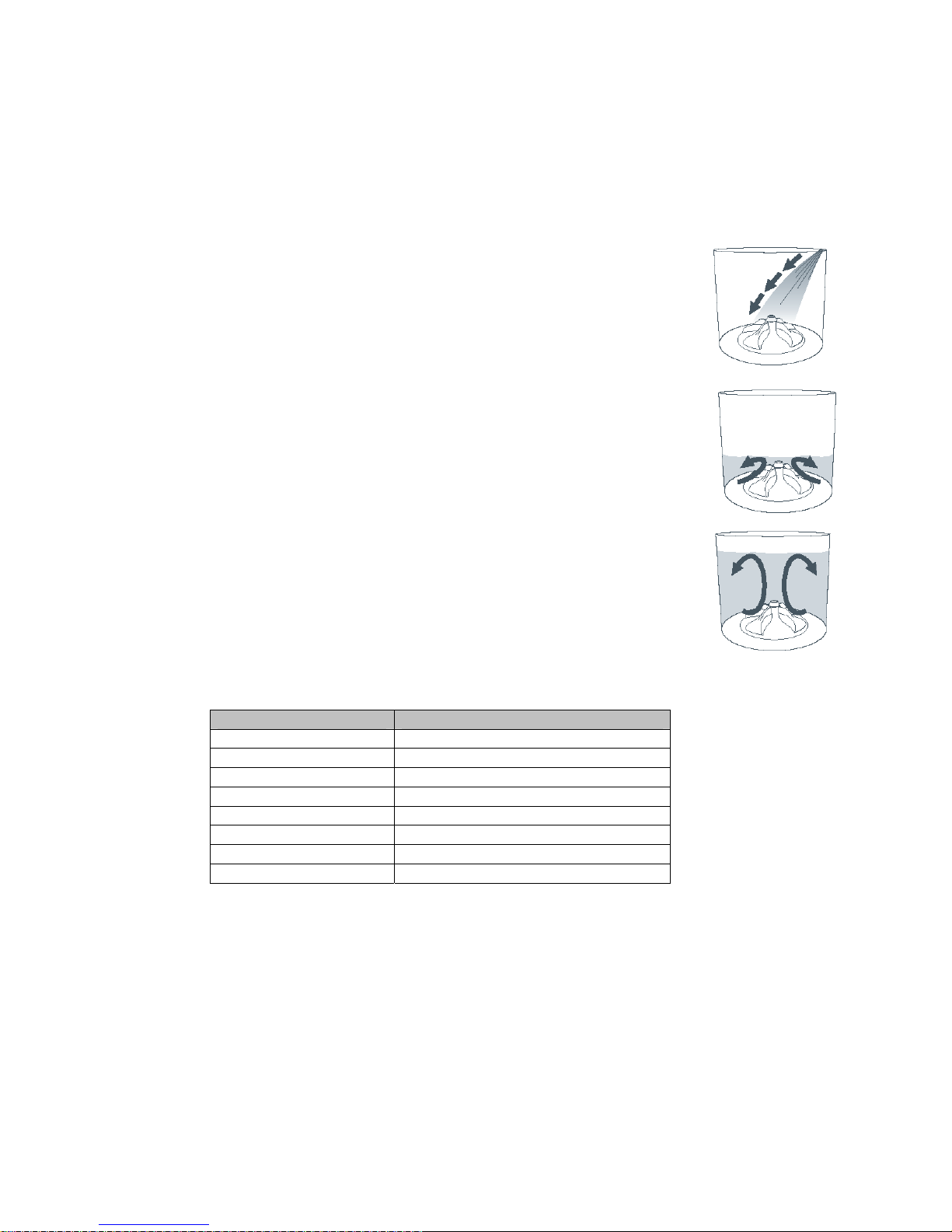
2 THE UNIQUE AQUASMART™ WASH
The AquaSmart is a EcoSmart based washing machine that has two modes of washing, High
Efficiency & Conventional. It is essentially a front loader (high efficiency mode) and a top loader
(conventional mode) washer in one.
Both washing modes start the same way, with a detergent activating wash.
Detergent Activating Wash
AquaSmart™ fills at the selected water temperature, with just enough water
so that the clothes are saturated. This concentrated detergent solution is
then re-circulated through the wash. This thoroughly dissolves and
activates the detergent.
High Efficiency Mode (front loader type wash)
In the High Efficiency mode, the AquaSmart™ fills with just enough water to
lift the clothes off the low profile agitator, so that when it rotates, the clothes
gently roll over each other. This wash uses similar quantities of water to
most Front Loaders and so, not only are there the benefits of water savings,
but also the higher detergent concentrations give optimum soil removal.
Conventional Mode (top loader type wash)
The Conventional mode is the immersion wash all Top Loader users are
familiar with. After the Detergent Activating Wash, the AquaSmart™ fills
with water until the clothes are underwater, whilst gently turning the clothes
over. We recommend this mode when the dilution effect of water can solve
or prevent common wash problems. For example when dye or colour run
can be a problem or when washing sandy towels. Sheets are better
washed in this mode. Some cycles can be used in both modes, whilst
others work in only one.
Cycle Modes Available
Regular High Efficiency
Sheets Conventional
Whites High Efficiency and Conventional
Colors Conventional
Heavy Duty High Efficiency and Conventional
Delicate High Efficiency and Conventional
Easy Iron Conventional
Bulky Conventional
Page 12

478182
12
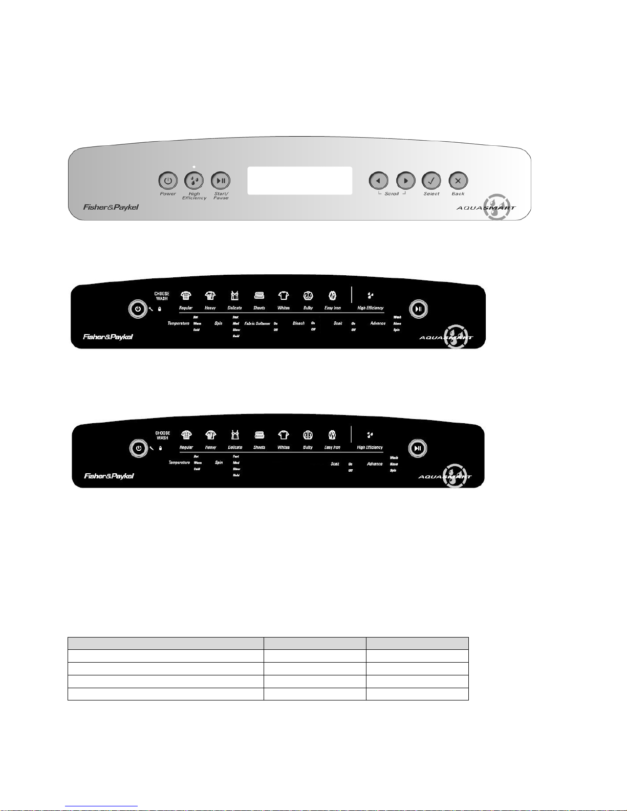
3 CONTROL PANEL
LCD Model
1. Power On/Off button.
2. High-Efficiency mode On/Off. When off, the machine uses the conventional wash mode
3. High-Efficiency LED used also for data download (refer to Section
6.3).
4. Start/Pause button
5. LCD Screen.
6. Left arrow (used when scrolling through options on the LCD screen).
7. Right arrow (used when scrolling through options on the LCD screen).
8. Select button – Use to confirm setting.
9. Back button - Use to cancel setting.
1 2 4
5
6 7 8 9
3
Page 13
478182
13
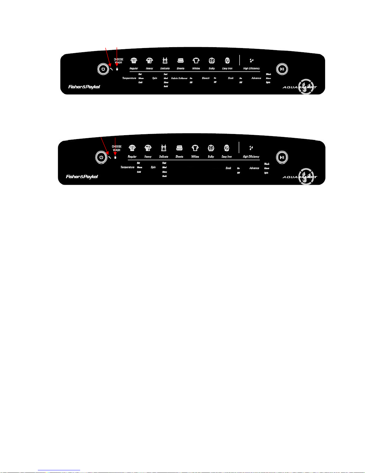
LED Model
1. Power On/Off button.
2. Service Spanner LED.
3. Lid Lock LED.
4. Regular button.
5. Heavy button.
6. Delicate button.
7. Sheets button.
8. Colours button.
9. Bulky button.
10. Easy Iron button.
11. High-Efficiency mode On/Off. When off, the machine uses the conventional wash mode
12. Start/Pause button.
13. Advance button.
14. Soak button.
15. Bleach button. (Not present on Non-dispensing model)
16. Fabric Softener button. (Not present on Non-dispensing model)
17. Spin Speed button.
18. Temperature button.
1
4 5 678910 11
12
2 3
13 1415161718
1
2 34 5 678910 11
12
13 141718
Page 14

478182
14
4 TECHNICAL OVERVIEW
This Service Manual contains information on the Product Specifications, Diagnostic Mode, Detailed
Fault Codes and the complete disassembly and assembly instructions for the AquaSmart
washing machines.
4.1 Electronics
4.1.1 Motor Control Module
The Motor Control Module used on the
AquaSmart washer is similar to the other
washers in its physical size and shape, however
the electronics have different software to control
the unique aspects of this machine.
Therefore the Motor Control Module is specific
to this machine and is not interchangeable with
any other machines.
The text on the yellow identifier label (P7SPL)
stands for Phase 7, SmartPump™, Low profile
Agitator.
4.2 Stand By Mode
If the machine has not received any instructions for 10 minutes after being switched on at the
power point, or after completing the cycle, it will automatically go into a low power “Stand By”
mode. The control panel will be blank as if it was powered off at the wall.
Before entering the Diagnostic or Option Adjustment mode, the machine must be taken out of the
Stand-By mode. To do this, the POWER button will have to be pressed, or the machine turned off
and back on at the power point.
4.3 Out of Balance Detection – ‘Bump Detect’
Past electronic machines have used a lever connected to a mechanical switch to detect if the load
in the inner bowl is out of balance. On this series of machine the system has been replaced with
electronic sensing known as ‘Bump Detect’. ‘Bump Detect’ is software written into the Motor
Control Module, which looks at specific feedback from the Rotor Position Sensor.
No fault codes are associated with ‘Bump Detect’, and there are no hard and fast tests that can be
carried out.
If a machine continually goes into an out of balance condition, then the following need to be
checked in the order given.
1. Even distribution of the clothes load.
2. Ensure that the machine is both level and stable on the floor.
3. Ensure that the feet have the rubber inserts fitted and the cabinet corners are clear of the
floor.
3. Check that any of the straps on the neck ring are not broken and that they are fitted
correctly.
4. Check the weight of the inner bowl. Bowl weight is as follows.
24lb 3oz +/- 10oz (10.965kg +/- 275g).
5. Check the RPS using a RPS Tester.
Page 15
478182
15
4.4 Water temperature Sensing
The thermistor for sensing the water temperature is located in the back of the outlet elbow on the
valve assembly, and is connected directly to the Motor Control Module.
Details for adjusting the wash temperature, Refer to the Use & Care Book.
Specifications
NTC-type temperature sensor (Thermistor)
Resistance 10,000Ω @ 77
o
F / 25oC
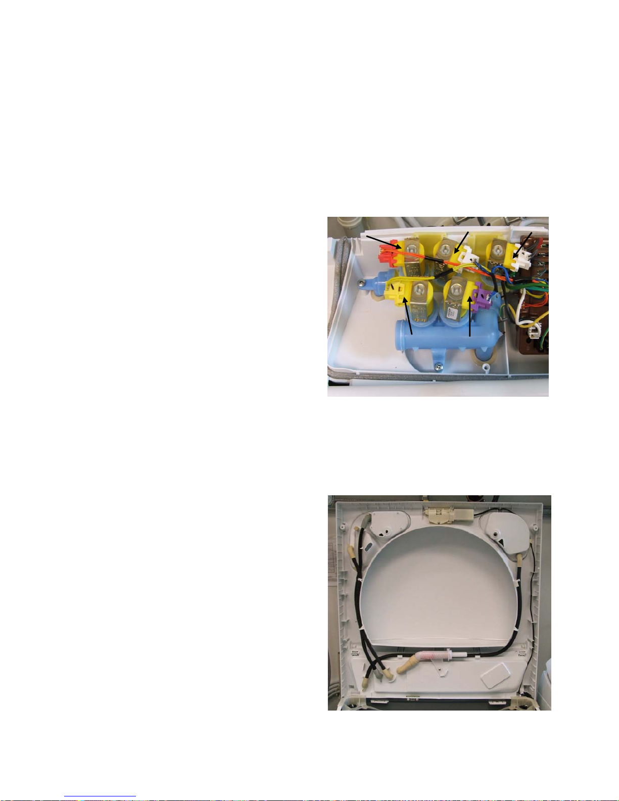
4.5 Water Valves
The water valve assembly incorporates up to
five valves that are joined by a common valve
body. The two main inlet coils control the flow
of water into the valve body assembly that then
in turn supplies water into the machine through
the inlet nozzle.
Up to three additional coils are used that
control the valves for the fabric, detergent and
bleach dispensing. They control the flow of
water to the fabric, detergent and bleach
dispensing system via hoses that run
underneath the top deck.
1. Hot coil (White Clip)
2. Cold coil (White Clip)
3. Fabric coil (Yellow Clip)
4. Detergent coil (Purple Clip)
5. Bleach Coil (Red Clip)
4.6 Dispensing System
Three hoses of different lengths run
underneath the top deck and connect to the
detergent dispenser, the bleach dispenser and
the fabric softener dispenser. The detergent
dispenser hose has cream elbows. The fabric
softener dispenser hose has grey elbows and
the bleach dispenser has red elbows.
Moulded into the top deck at the valve end are
identification letters (‘D’ for Detergent and ‘S’
for softener & ‘B’ bleach). At the dispenser
end are moulded the words ‘Detergent’,
‘Softener’ and ‘Bleach’.
It is important that the hoses are retained in the
clips around the perimeter of the opening of
the top deck correctly.
5
3
4
Page 16
478182
16
4.6.1 Detergent Dispensing
During fill, the detergent valve is also energised. This allows a proportion of the inlet water to flow
into the detergent dispenser.
The flow rate through the detergent valve is dependent on the inlet water pressure, but it is less
than the flow rate of water entering the machine. The valve will remain energised until the water
level reaches 1 inch (25mm), at which point the bowl starts stirring until the desired water level has
been achieved.
The detergent valve can be tested in diagnostics (refer to Section
6.1.2 for LCD models, or Section
7.2 for LED models).
4.6.2 Bleach Dispensing
The design of the bleach dispenser is such that it creates a self-siphoning effect. When the motor
control module calls for bleach ¾ of the way through the wash portion of the cycle, the bleach
valve will energise. This allows water to flow into and through the dispenser mechanism. The
valve is pulsed on and off for a total of 95 seconds (see table below) to ensure that all of the
bleach has dispensed.
Siphon Pulse On Off
1st 10 s 15 s
2nd 10 s 10 s
3rd 10 s 10 s
4th 10 s 10 s
5th 10 s remains off
Note: The 1st off time of 15 seconds is to ‘kick start’ the siphoning process.
If the bleach valve was to run continuously, the water would cut a path through the bleach and the
bulk of the bleach would remain in the dispenser. The maximum level of the bleach is 120mls to
the ‘Max’ mark. If the bleach dispenser was to be filled higher than this mark, the bleach may selfsiphon into the machine.
The bleach valve can be tested in diagnostics (refer to Section
6.1.2 for LCD models, or Section
7.2 for LED models).
4.6.3 Fabric Softener Dispensing
The design of the softener dispenser is such that it creates a self-siphoning effect. When the
motor control module calls for softener at the beginning of the deep rinse cycle, the softener valve
will energise. This allows water to flow into and through the dispenser mechanism. The valve is
pulsed on and off for a total of 95 seconds (see table below) to ensure that all of the bleach has
dispensed.
Siphon Pulse On Off
1st 10 s 15 s
2nd 10 s 10 s
3rd 10 s 10 s
4th 10 s 10 s
5th 10 s remains off
Note: The 1st off time of 15 seconds is to ‘kick start’ the siphoning process.
If the softener valve was to run continuously, the water would cut a path through the softener and
the bulk of the softener would remain in the dispenser. The maximum level of the softener is
70mls to the ‘Max’ mark. If the softener dispenser was to be filled higher than this mark, the
softener may self-siphon into the machine.
Page 17
478182
17
The Softener valve can be tested in diagnostics (refer to Section
6.1.2 for LCD models, or Section
7.2 for LED models).
4.6.4 Inlet Nozzle
In addition to its design, which ensures excellent rinse water distribution, the nozzle shares an
important relationship with the inlet valve assembly and the dispensing system as described
above.
An internal piston within the nozzle moves with the amount of water pressure against it. When the
water pressure is high, more holes in the nozzle are exposed, and the backpressure on the
dispensing valves is less.
When the pressure is low, more backpressure is created, which ensures that either during
detergent dispensing or bleach dispensing the dispensing system takes priority.
If the water pressure was very low during dispensing, it is conceivable that no water would enter
the machine via the inlet nozzle until the dispensing has been completed.
Conversely, if the piston was jammed and the water pressure was high, a high flow rate of water
would go through the dispensing system and may result in water on the floor.
4.7 Water Level Measurement
The AquaSmart uses the same pressure sensing system used in the EcoSmart and Intuitive
Eco™ machines to determine the water level. The difference with AquaSmart is that on both the
Conventional and High Efficiency modes, AquaSmart will automatically choose the water level,
as the precise water level for the clothes load is critical to the performance of the wash. The
amount of water used in either mode is unable to be selected or adjusted by the user.
So now there are an infinite number of water levels that AquaSmart can choose depending on
the weight and type of the clothes being washed.
4.8 Motor
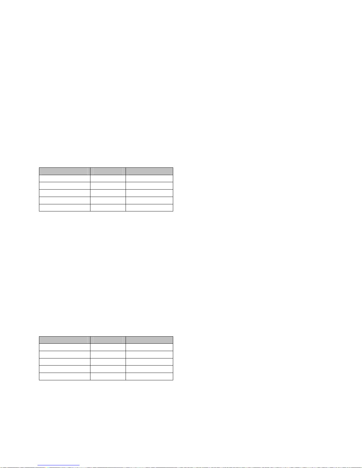
4.8.1 Stator
This stator used on the AquaSmart machine is unique to this series only and therefore are not
interchangeable with any previous phase or series of machines. The stator has 36 poles with
pole tips being curved. The windings are Aluminium and can be Identified by the printed marking
AL 60 190T it looks the same as the Previous copper Stator but is 19.5 per winding. The rotor
position sensor is also unique to this stator. (Refer to Section
4.8.3)
Aluminium Stator (36 Poles) Curved pole tips
Page 18
478182
18
Testing the Stator
If the stator needs to be tested we would first recommend testing the resistance of the windings
from the harness end that is connected to the Motor Control Module. (Refer to Section
5.2).
Note: Ensure that the Rotor or basket is stationary when measurements are made.
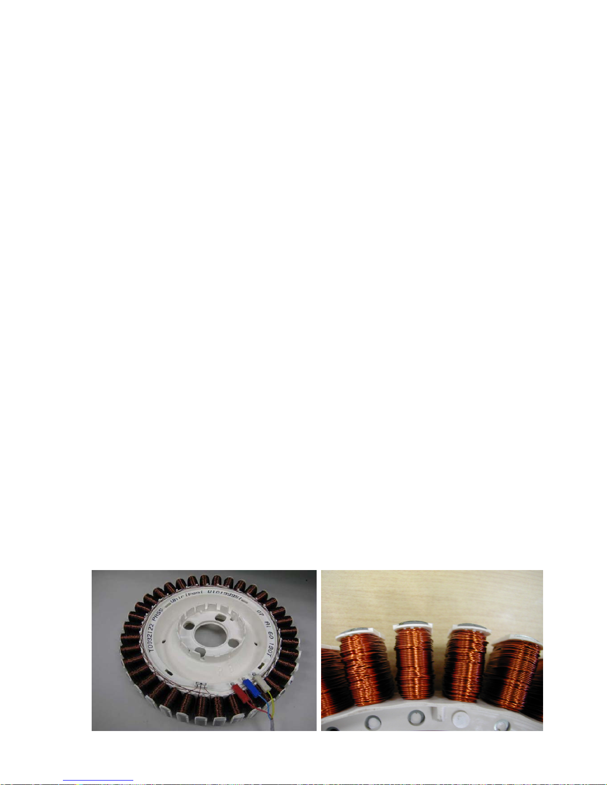
Testing the stator from the console
The resistance of each individual winding is approximately 19, however when testing the stator
from the console we are testing across two windings therefore the resistance should be approx.
39 +/- 10%.
To test all windings you will need to measure across:
Red & Blue
Blue & Yellow
Yellow & Red
If the meter shows an incorrect reading we would then recommend testing the stator from
underneath the machine, as there could be a fault in the wiring harness. To test the stator, both
rotor and stator need to be removed. (Refer to Sections
10.23and 10.24).
Note: Two clamp plates are used to secure the Stator, one on each side. The four bolts are
tightened to a torque of 44in/Lbs (5Nm). The plastic bolt for securing the Rotor requires a
5/8” (16mm) socket and should be tightened to70 in/lbs (8Nm)
Testing the Stator
After removing the Stator, it can now be tested.
Test points are:
R / B
B / Y
Y / R
The value should be approx. 39 +/- 10%
across any of the two windings.
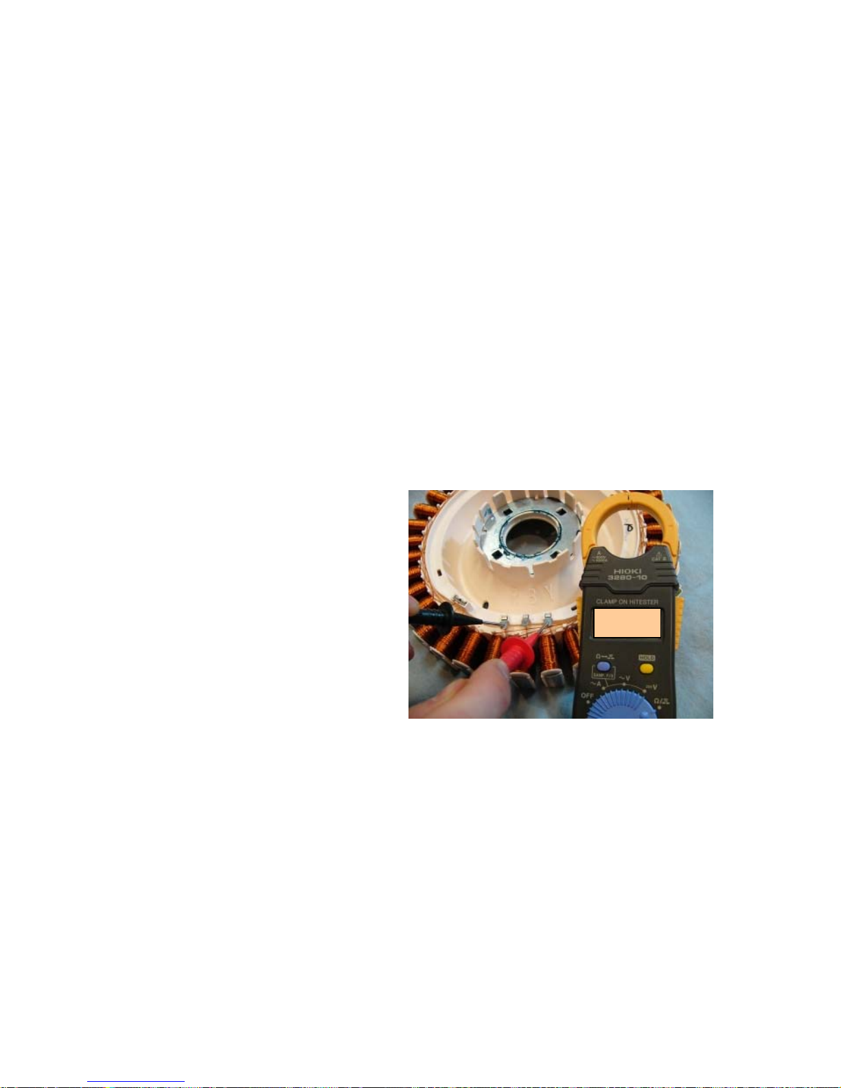
4.8.2 Rotor
The rotor is also unique to this series of AquaSmart machines. It has 48 blocks of individual
magnets in a black moulding, as opposed to earlier machines having 16 blocks, containing 3
magnets in a white moulding.
The rotor is not interchangeable with any previous phase or series of machine.
The rotors can physically be interchanged, however electrically they are incompatible.
If the black rotor is fitted to earlier machines, fault code 240 will occur. Conversely fault code 240
will also occur if a white rotor is fitted to an AquaSmart machine.
The photographs below show the difference between black and white Rotors.
39.0
Ω
Page 19
478182
19
Current Black Previous White
4.8.3 Rotor Position Sensor
One of the inputs that the Motor Control Module needs in order to determine which switches to turn
on is the position of the rotor. The rotor position sensor (RPS) supplies this information.
The rotor position sensor (RPS) is a printed
circuit board that contains three Hall Sensors,
which detect the magnetic field of the individual
magnets in the rotor. The RPS provides this
information to the Motor Control Module. The
printed circuit board sits in a black plastic
housing encapsulated by resin to protect the
board. The only exposed area of the board is
the connector for the main harness. Only the
black RPS will work with the black rotor.
Note: The RPS is not interchangeable with
any previous phase or series of machine.
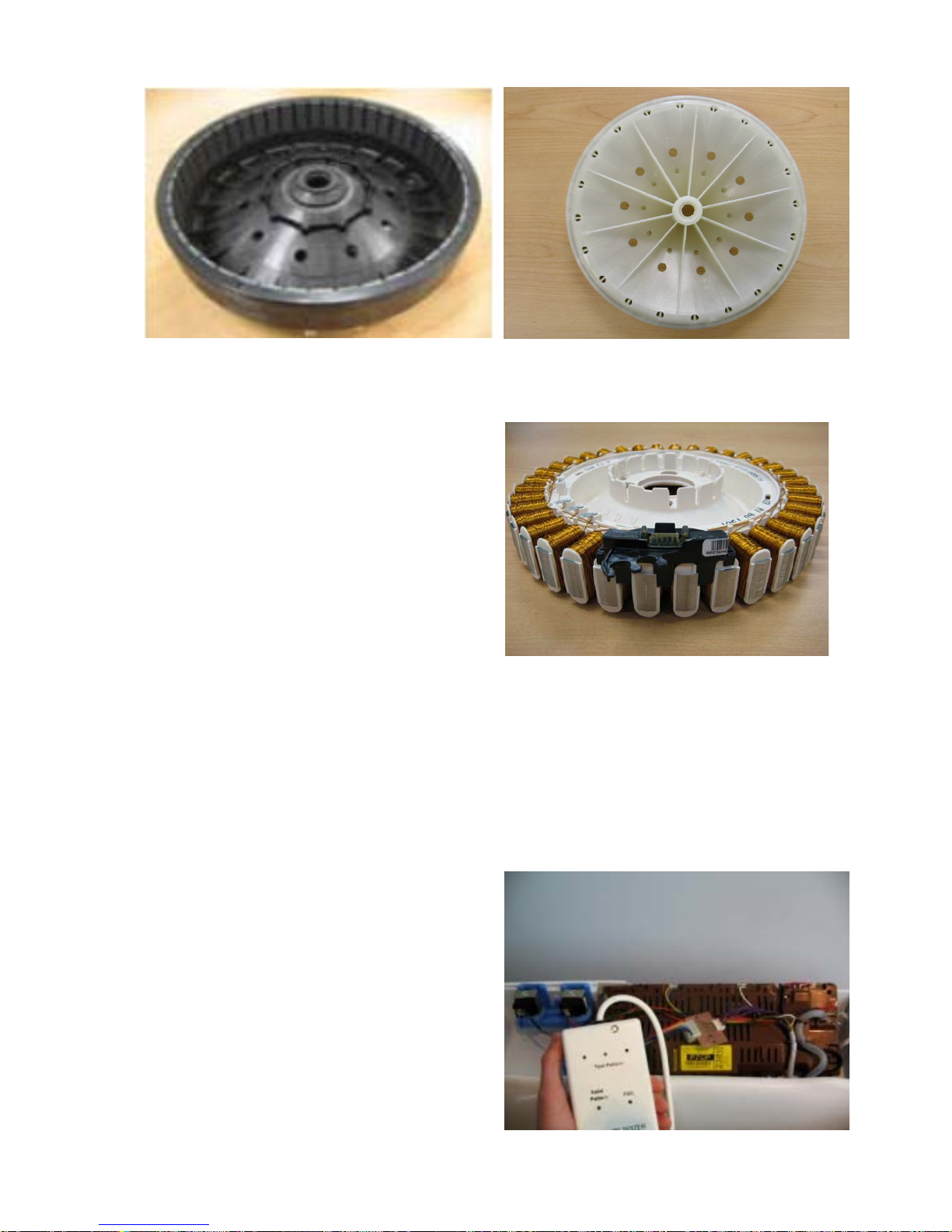
Testing the Rotor Position Sensor
To test the RPS use a RPS tester kit, part number 479413, this is powered by a 9V battery. To
test the RPS follow the detailed instructions which are enclosed with the tester. The tester has 3
LEDs, and the pattern of these LEDs will change as the magnetic field of the Rotor passes the hall
sensors.
Connect the RPS tester to the RPS harness. Slowly turn the basket and note the pattern of lights.
A valid pattern is a pass. A fail will indicate a failure of either the harness or the RPS. If a failed
pattern is showing, connect the RPS tester directly on to the RPS at the stator and retest.
A pass is when 1 or 2 LEDs are illuminated at a
time, 0 or 3 LEDs illuminated indicates fail. Any
flickering of the fail LED will indicate that the
RPS or rotor is faulty. A faulty rotor would give
a fail at certain points of rotation.
Page 20
478182
20
Note: This tester does not test all the functionality of the RPS. It tests the 3 outputs but
cannot indicate all faults, for example if a capacitor on the RPS is cracked.
The rotor may also be tested with a RPS Tester. A complete rotation will test all the magnets.
If the rotor has cracked or chipped magnets it will work fine, and does not need to be replaced.
4.9 Smart Pump
SmartPump™ provides a more flexible and efficient pumping system than a conventional
pump/diverter valve combination. SmartPump™ can be diverted quickly; it reacts faster and is
better controlled. In addition, SmartPump™ has the capability of pumping to a much higher head
whilst maintaining a constant volume flow rate regardless of pump efficiency degradations due to
age.
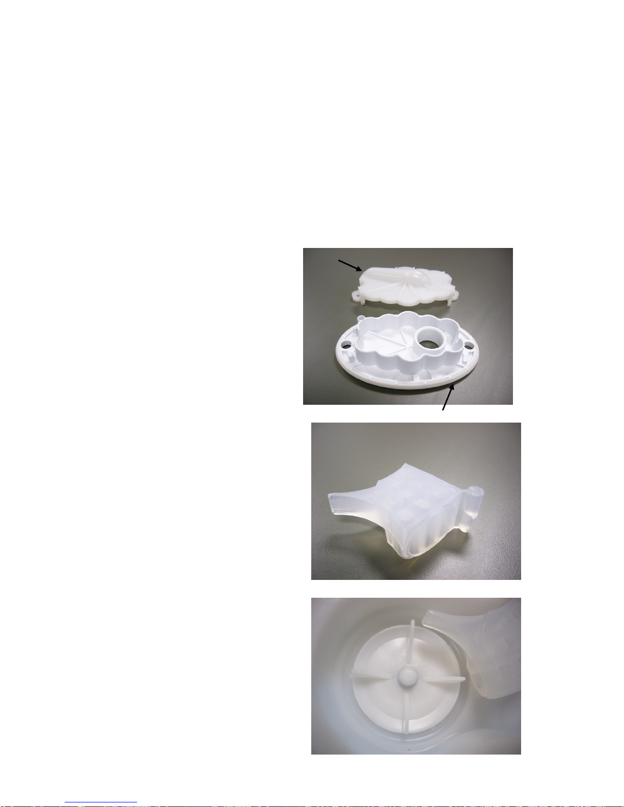
4.9.1 Hood and Cap
The hood and cap form the top of the pump
housing, which must seal to the outer bowl.
The hood and cap filters out objects that
cannot pass through the pump system.
4.9.2 Flapper Valve
A diverter valve has been integrated into the
pump cavity and operates automatically with a
change in pump direction. This change of
direction moves a flapper valve, which diverts
the water to the drain hose or to the recirculation hose. The valve is sealed off
against the port face with water pressure.
4.9.3 Impeller (non-field serviceable)
The impellor imparts rotational energy into the
water and keeps sand away from the shaft
seal.
Cap including integrated seal
Hood
Page 21
478182
21
4.9.4 Rotor and Stator
The rotor and stator magnetically interact with each other in order to convert electrical energy into
rotational movement of the rotor
Rotor
The rotor assembly is a complete unit that is
permanently fixed into the pump housing. The
resulting cavity is charged with water, which
acts as a lubricant. In the event of a failure of
the rotor, the whole assembly must be
replaced.
Note: Contained within the rotor cavity are
seals and bearings that are non field
serviceable. The bearings provide a low
friction wear surface for the rotor shaft to run
on, and the seals eliminate grit from the rotor
and bearing cavity
Stator & Shield
The Stator is mounted to the base of the pump
housing together with the shield & cap. The
harness connector inserts into the underside of
the motor. Care must be taken to isolate the
machine from the mains power before
servicing the pump, and it is important that the
harness connector cover has been refitted
after reassembly.
4.9.5 Pump Housing
The pump housing is bolted directly to the
outer bowl. It contains the volute shape and
flapper sealing faces and also provides a
structure to attach stator and rotor assemblies.
Rotor within water filled cavity
Stator
Shield
Page 22

478182
22
4.9.6 SmartPump™ Spare Parts
The following spare parts service kits are available for SmartPump™.
Hood And Cap (SmartPump™) Kit
P/N 479418
Flapper (SmartPump™)
P/N 420403
Seal (SmartPump™) Housing
P/N 479420
Pump Assembly (SmartPump™) Kit
P/N 479417
Note: The pump assembly is supplied with
the connector removed from the stator
shield. The cover must be fitted in place
after the wiring harness has been attached.
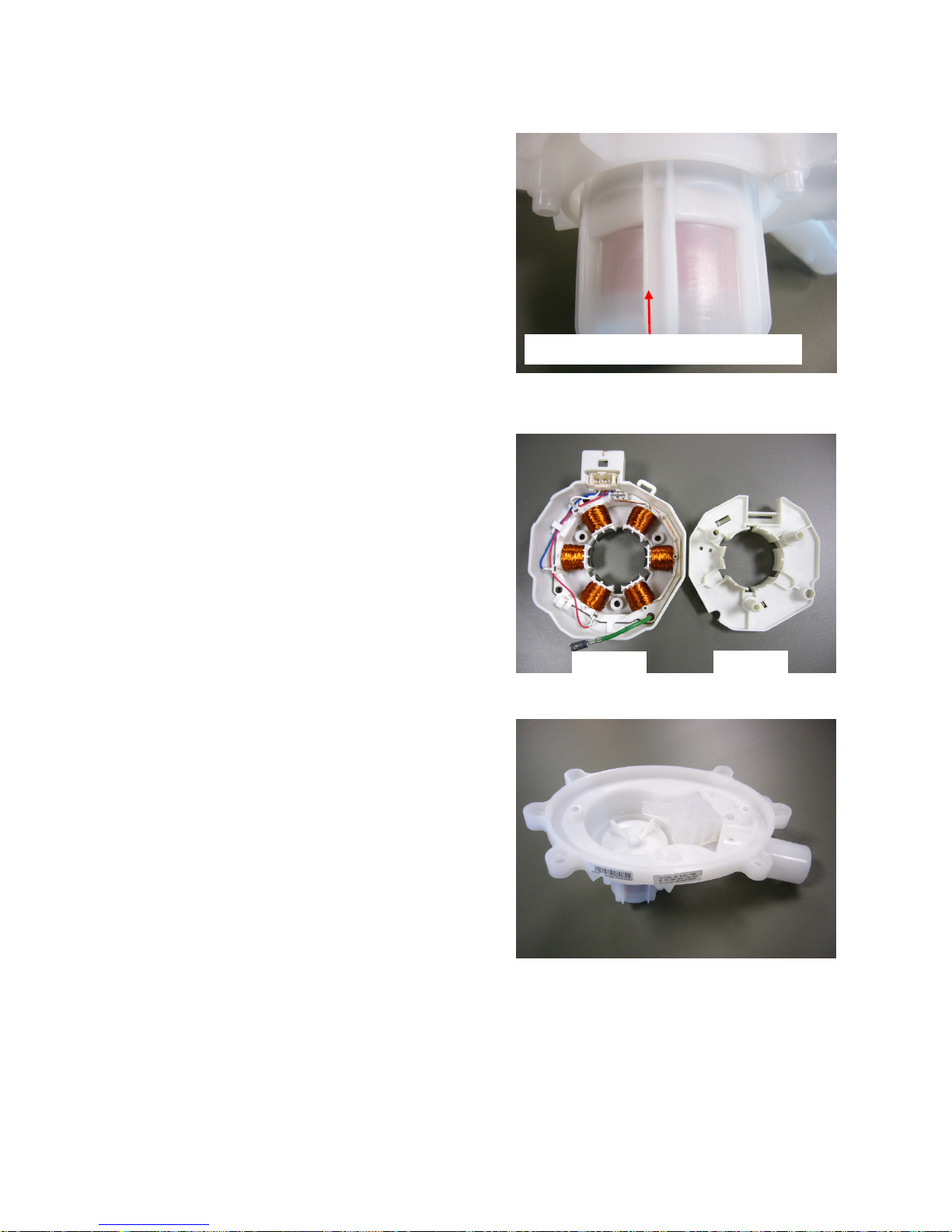
4.9.7 SLR Feature
SLR stands for Simplified Leak Recirculation.
This feature has been added so that should the
flapper not completely seal against the housing
of the pump when draining, water can bypass
through this hole and back into the pump,
avoiding re-circulating back into the bowl and on
to the washing load.
It is important that this hole remains clear, and it
should be checked whenever the pump is
serviced.
Connector cove
r
Page 23
478182
23
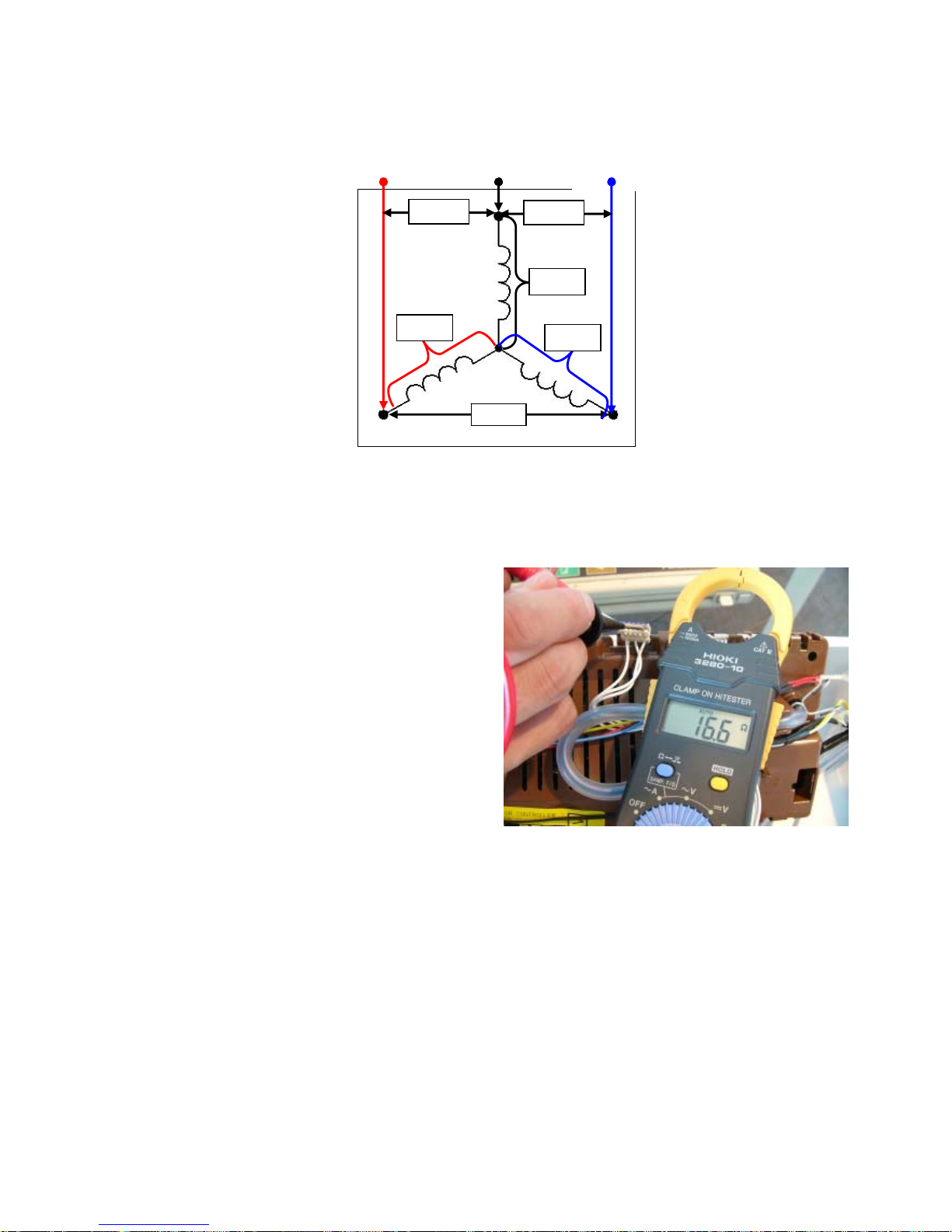
4.9.8 Testing the Pump Stator
SmartPump™ Wiring Diagram
The stator resistance can either be tested from the harness at the motor controller or at the
connections to the stator itself.
4.9.9 Testing SmartPump™ Stator from the Console
The resistance of each individual winding is
approximately 8.1Ω +/- 10%, however when
testing the stator from the console we are
testing across two windings, therefore the
resistance should be approximately 16.2Ω +/10%.
To test all windings you will need to measure
across:
• Red and White
• White and Blue
• Blue and Red
If the meter shows an incorrect reading, we would recommend testing the stator from underneath
the machine, as there could be a fault in the wiring harness. To test the stator it will need to be
removed from the machine (refer to Section
10.19).
BLUE
RED
WHITE
16.2Ω
16.2Ω
8.1Ω
8.1Ω
8.1Ω
Page 24

478182
24
4.9.10 SmartPump™ Test Routine
Use the following procedure to test the SmartPump™. It is equally important to test both the drain
and recirculation modes. In diagnostic mode the lid lock is disabled, which allows the technician to
visually inspect both aspects of the pump.
1. Enter diagnostic mode. (Refer to Section
6 for LCD models, or Section 7 for LED models.)
2. If the inner basket is empty of water, activate either or both of the water valves until the inner
basket is approximately 1/4 full with water. (Refer to Section
6.1.2 for LCD models, or Section
7.2 for LED models.)
3. While in diagnostic mode, set the pump to Recirculation Mode (refer to Section
6.1.2 for LCD
models, or Section
7.2 for LED models), run for at least 1 minute and observe the following:
Ensure that a good flow rate is being delivered through the portal of the hose.
Ensure that a good pattern of flow is being delivered. If a poor flow rate is apparent, firstly
check that the neck ring is fitted correctly and is not obstructing the flow of water.
Secondly, remove the neck ring and check the shape and location of the recirculation
nozzle is as expected. If no faults are found, the pump must be inspected. To access the
pump cavity, (refer to Section
0).
Ensure that no leaks are occurring from either the recirculation hose where it attaches to
the outer bowl (to do this the top deck will need to be lifted, refer to Section Error!
Reference source not found.), or where it attaches to the SmartPump™.
Ensure that no water is exiting from the drain hose. If it is, this indicates that water is
bypassing. For the description of bypassing, refer to Section
4.9.11.
4. Again, whilst in diagnostic mode, set the machine to drain (refer to Section
6.1.2 for LCD
models, or Section
7.2 for LED models), run for at least 1 minute or until all water has been
drained, and observe the following:
Ensure that a good pattern of flow is being delivered. If a poor flow rate is apparent the
pump must be inspected. To access the pump cavity, refer to Section
0.
Ensure there are no leaks from where the drain hose exits from the cabinet or at the pump
housing.
Ensure no water is exiting from the recirculation hose. Again, this would indicate that
bypassing is occurring.
4.9.11 Bypassing
Bypassing is the term given to water that either flows from the recirculation hose when the pump is
draining, or from the drain hose when the pump is re-circulating. No water at all should exit from
the opposing hose. The flapper valve not sealing against the face of the pump cavity, or a poor fit
of the hood and cap can generally cause bypassing.
If bypassing occurs, the pump (including the SLR Feature (refer to Section
4.9.7) must be
inspected. To access the pump cavity (refer to Section
0).
Page 25

478182
25
4.10 Lid Lock
AquaSmart uses the same lid lock that is used
on previous machines, and is locked during the
complete cycle.
The Lid Lock symbol (padlock) appears in the
top right hand corner of the screen on LCD
models, and in the centre left next to the power
button on the control panel on LED models,
letting you know at a glance if you can open
the lid or not.
To unlock the lid at any time, press START/PAUSE.
If the lid is left open on the AquaSmart™, the
machine will be unable to lock the lid, and the
cycle will be halted. The machine will beep and
on the LCD model display a message to alert
the user, with the padlock symbol flashing on
the LED model. If this occurs, ensure that the lid
is closed, and press the START/PAUSE button.
If the lid-lock fails in the closed position, the locked lid can be forced upwards and out of the lock.
Note: This is the only time in which we would recommend doing this.
If the harness is damaged, the complete lid lock assembly will need to be replaced.
If the power supply is cut during the spin cycle, the machine will keep the lid locked until the rotor
has ceased to turn (3 to 10 seconds). Only then will it release the lid from the lock. The motor is
acting like a generator and allows the lock to stay energised under the bowls inertia.
In a brown out situation (where power is lost only momentary), the machine will restart at the start
of whichever section of the cycle it was on and continue the wash.
The lid is locked throughout the complete cycle.
Eco-Active
Locked
Agitate
Locked
Spray Rinse
Locked
Deep Rinse
Locked
Spin
Locked
Page 26

478182
26
4.11 Neck Ring
The neck ring incorporates wells used for the
fabric, detergent and bleach dispensing.
The neck ring is clipped in place to the outer
bowl. It also restrains the re-circulating nozzle.
It is important that the neck ring is secured
correctly to the outer bowl, as it affects bump
detect (out of balance detection). The bowl
assembly may experience more movement,
which could lead to cabinet damage.
Dynaflex straps are located at four points on the
neck ring and connect to lugs on each of the
suspension rods.
The straps serve two purposes:
1. To limit radial bowl motion during agitation.
2. As the straps stabilise the bowl, it also
improves wash performance.
If one or more straps break, this can cause an
increase in out of balance activity, which again
may lead to cabinet damage and noise from
loose straps, always replace the straps never
refit them.
For a detailed explanation of Bump Detect,
(refer to Section
4.3).
4.12 Inner Basket and Outer Tub
The outer tub is the assembly to which all the motor, pump system, suspension rods, etc are
mounted. Within the outer tub is the inner basket and the agitator. During spin, the agitator and
inner basket have to be coupled together and turn as a single unit. In agitate; the agitator and
inner basket are free to rotate independently.
The inner basket is free to move in a vertical direction. The position of the inner basket is
determined by the water level. At the base of the inner basket is a flotation chamber consisting of
a number of individual cells. When the machine is filling with water, the pressure on the air in
these cells increases as the water level rises until eventually the inner basket floats upwards and
disengages the driven spline from the drive spline. This action frees the agitator from the inner
basket and allows it to move freely in both directions.
When the water is draining, the pressure on the air trapped in the cells of the flotation chamber
decreases allowing the inner basket to settle back down onto the drive spline and re-engage the
driven spline, thus allowing the agitator and inner basket to turn as one unit. The floating basket is
also used to detect if the correct water level for the size of the clothes load.
The point at which the basket starts to float is determined by the water level and the size of the
load. The greater the load, the more water is needed before the inner basket will float. By
detecting the point at which the basket floats, the machine can determine whether the correct
water level for the particular clothes load has been reached
Page 27

478182
27
4.12.1 Detection of Inner Basket Float Off Point – Basket Check
During fill the inner basket will rotate to ensure that the clothes are evenly saturated with water.
When the chosen water level is reached, and before the agitate cycle is started, the machine will
carry out inner basket float checks (basket check). The inner basket will stop and commence a
number of small agitate type actions. During this action the machine determines if the inner basket
has floated if it has, the machine determines the correct water level has been reached. If the inner
basket has not floated, the machine will continue filling and check again later. The water level at
which the inner basket floats is not necessarily the same as the final water level.
4.12.2 Detection of Inner Basket Re-Engagement – Basket Check
After the water has drained, the inner basket will sink down and re-engage onto the drive spline.
To ensure the inner basket has re-engaged correctly, the machine will carry out a basket reengage test sequence (basket check). Basket check consists of a series of short agitate type
actions before the spin cycle starts. A sound may be heard as the inner basket re-engages.
4.12.3 Inner Basket
EcoSmart AquaSmart
4.12.4 Balance Ring
The inner basket for AquaSmart has a new top balance ring, which has 2 internal chambers
instead of just one as on EcoSmart bowls. Both chambers are ½ filled with water.
The physical appearance of the balance rings changes from a square profile to a curved profile.
4.12.5 Inner Basket Base
The new basket used on the AquaSmart has all 3 chambers partially filled with water where as
the basket base used on large EcoSmart (one with the internal bumps) has only the inner and
middle chambers filled with water.
IMPORTANT
It is important that the new inner bowl for AquaSmart
is only used on AquaSmart
models. If the inner bowl is fitted to an EcoSmart
, it will cause the bump detect software
not to function correctly, leading to increased cases whereby the inner bowl could hit
against the top deck and cabinet.
Conversely, an EcoSmart
inner bowl should not be fitted to AquaSmart.
Page 28

478182
28
4.13 Suspension Rods
The suspension rods on AquaSmart need to be more robust than the suspension rods used on
previous EcoSmart machines. The top bracket has lugs to which the straps from the neck ring
attach.
A rubber washer sits midway down the rod, this helps detergent residue from running down the rod
and into the grease filled damper.
IMPORTANT
It is important that these suspension rods are used only for AquaSmart
machines.
These rods haven’t been tested on EcoSmart
machines, however if they were to be fitted it
is likely that there will be an increased level of noise and vibration on spin.
Conversely, rods from a EcoSmart
should not be fitted to AquaSmart.
There is also an increased chance that the inner bowl may strike against the top deck on
spin up.
The current machines use the suspension rods
on the left.
This new rod provides even greater dampening,
and assists in preventing out of balance loads.
Lugs to which the neck ring straps attach
Rubber washer
Service Version
“B” (early)
Service Version
“B” (current)
Page 29

478182
29
4.14 Agitator Low Profile
The unique low profile agitator works well in both the High Efficiency and Conventional modes. In
the High Efficiency mode, the clothes have greater contact with the agitator due to the low water
level, and the agitator ensures a high level of clothes turnover.
In Conventional mode, the clothes are completely submerged in the water and the curving steep
side walls and raised shoulders of the wash plate vanes create enough inward and upward
movement to keep the clothes turning over even when there is reduced contact with the agitator.
Top View Underside View
4.15 Control Panel
The three core components of the control panel on the LCD model are the console, the IMD facia,
and the PCB and housing. A new look that differs from existing machines has been created, so
now capacitive touch buttons drive a high-resolution dot matrix display. The facia provides a sleek
look and no protruding buttons makes it easier to clean.
Console:
The console, which is made from ABS, is the
housing to which the facia and PCB housing
attaches. Lugs at the base of the console
locate into the top deck. The console is secured
to the rear of the top deck by two screws.
IMD Facia – LCD Model
IMD stands for In Mould Decorative display.
Clear plastic is molded over the decorative
polycarbonate silver film. The last process is to
mould the seal on to the facia. The IMD
process means a reduction of parts and any
subsequent printing process.
• No lens.
• No light pipes.
• No separate buttons.
• No separate seal.
Page 30

478182
30
PCB and Housing – LCD Model
The PCB, which contains the capacitive touch
buttons and LCD, is mounted within a plastic
housing. The PCB housing is clipped into the
console at the bottom, and secured with four
screws along the top.
Facia – LED Model
Is a clear plastic molded insert with an adhesive
backed touch panel fitted
PCB and Housing – LED Model
The PCB, which contains the touch buttons and
LED’s, is mounted within a plastic housing. The
PCB housing is clipped into the console at the
bottom, and secured with four screws along the
top.
Page 31

478182
31
5 VOLTAGE AND RESISTANCE READINGS FROM
THE CONTROLLER
5.1 Voltage Readings
1 2
3 4 6 5 7
8
1. Water Valves
Varies between 13 – 22V DC
Note: Accurate voltages can only be
obtained by using a True RMS multimeter.
2. Supply voltage
110V AC
3. Wash Motor
No accurate readings are possible.
4. Pump Motor
No accurate readings are possible.
5. RPS
6. Display Module
7. Lid lock
8. Thermistor
0 – 5 V DC
Pulses up to 30V when locking, when
locked, sits at approx 10V DC
5 V DC
Should always
be 15V DC
Individual phases will be 15 or 0
volts
,
will change as motor turns
Page 32

478182
32
5.2 Resistance Readings
1
2 3 4 5
6
1. Water Valves
64 Ω +/- 10%
2. Wash Motor
3. Pump Motor
4. RPS - Unable to be tested with
multimeter.
5. Lid lock
6. Thermistor
16.2Ω across any two windings
63Ω +/- 10% @ 68oF / 20oC
39Ω across any two windings
10,000Ω @ 77oF / 25oC
Page 33

478182
33
6 DIAGNOSTIC MODE – LCD MODEL
To enter the DIAGNOSTIC MODE, turn the power on at the power point and off at the console.
Press and hold the HI-EFFICIENCY and SELECT buttons. Keep the buttons pressed for at least 2
seconds, after which time two beeps will sound and the screen below will appear.
Use the left and right scroll arrows to highlight the screen you wish to view, then press the select
button to enter that screen.
The screens are explained below.
6.1 Service Screen
Upon entering the service screen, one of the following screens will appear
Warning Status / Fault Status
Machine Status
To scroll between the screens use the left and right scroll arrows.
6.1.1 Warning Status Screen / Fault Status Screen
Warning Status
In this screen will be displayed the last USER
WARNING FAULT that occurred and will show
how many cycles ago and in what part of the
cycle it occurred.
The User Warning Faults are as follows:
No Faucets
Overloaded
Out Of Balance
Over Suds or water still in the machine
during spin
No Hot Water
No Cold Water
Agitate Overloaded
Fault Status
In this screen will be displayed a fault code for
the last fault that has occurred and will show
how many cycles ago and in what part of the
cycle it occurred.
The fault code number can now be checked in
the detailed fault codes, to ascertain what
repairs may be necessary.
For fault code details refer to section
8.
Press and hold the HI-EFFICIENCY and SELECT buttons for 2 seconds
Page 34

478182
34
6.1.2 Machine Status Screen
In the top half of the screen it displays the
following information.
Size is the size of machine, (650mm = Large)
HVDC is for on line testing in the factory.
WL displays the water level in mm.
T is the actual temp of the inlet chamber water.
Target temp is the temperature selected.
In the lower half of the screen it displays the status of the following components.
Hot Valve (HOT)
Cold Valve (COLD)
Detergent Valve (DET)
Softener Valve (FAB)
SmartPump™ (PUMP)
Bleach Valve (Blch)
Component Testing
In this screen the components that are displayed can be tested. To test a component, firstly
highlight the component by using the left and right scroll arrows. To activate a component, press
the select button. To deactivate the component, depress the select button again.
Note: SmartPump™ can be tested in both the drain and recirculation modes. After
highlighting Pump, the first press of the Select button activates the pump in the drain
direction, the second press activates the pump in the recirculation direction, a final press
turns the pump off.
6.2 Control Screen
6.2.1 Hot Bowl Flag
If the machine has been filled with the hot water valve utilised (i.e. warm or hot fill) and has not had
a cold rinse, the electronics will not allow the machine to spin up to its full speed of 1000 RPM. It
will only allow the spin speed to reach 700 RPM.
To remove this flag, enter the Control Screen mode and push the HI-EFFICIENCY button. This
flag can also be removed by putting the machine through a complete final rinse.
Page 35

478182
35
6.2.2 Restart Feature
The LCD AquaSmart™ leaves the factory with the RESTART set to the ON position, which is
indicated in the screen by the word RESTART highlighted. To turn the RESTART feature OFF,
push the Left scroll arrow. This will remove the highlight from the word RESTART. When the
machine is being serviced, it is more convenient to turn the RESTART feature OFF. This will allow
any fault in the system to show up immediately it occurs.
With the RESTART feature on:
1. If a fault occurs in the machine, the diagnostic system will detect it. However, instead of
displaying a fault code immediately, the machine will try to RESTART.
2. If the fault was only of temporary nature, the machine will restart and finish the cycle.
3. If there is a continuous fault the machine will try to RESTART a number of times. This
process could take up to 8 minutes depending on the type of fault. After this, if the machine
still cannot restart, the fault code is displayed and the machine will beep continuously.
NOTE - This feature is designed as a service aid only and should be left ON in the
customer’s home. To return to normal operation, and to reset the RESTART feature to the
factory setting, switch the machine off at the wall or disconnect from the mains supply.
To identify that the RESTART feature has been activated, refer to the Restart / Recycle table.
(Refer to Section
6.2.4)
6.2.3 Recycle Feature
At the end of servicing, the machine may require an extended test where the machine can be left
to complete a number of wash cycles. By turning on the RECYCLE feature, the machine will
continuously repeat the wash cycle until the RECYCLE feature is turned off. To toggle this feature
on or off, press the right scroll arrow. When the recycle feature is on, the word RECYCLE will be
highlighted.
NOTE - This feature is designed as a service aid only and should be OFF in the customer’s
home. To return to normal operation, and to return the recycle feature to the factory
setting, switch the machine off at the wall or disconnect from the mains supply.
To identify that the RECYCLE feature has been activated, refer to the Restart / Recycle table.
(Refer to Section
6.2.4)
6.2.4 Restart / Recycle Table LCD
As the LCD AquaSmart™ has only one LED (located above the High Efficiency button) the state of
the LED will signify which feature has been selected or not selected. The table below explains the
state of the LED when the machine is on at the wall and off at the machine.
LED: Off (Factory Default) Restart on
Recycle off
LED: Solid Restart off
Recycle on
LED: Slow Flashing Restart off
Recycle off
LED: Quick Flashing Restart on
Recycle on
Page 36

478182
36
6.2.5 Restart/Recycle Features Permanently Programmed
It is possible for the Restart Feature to be disabled, or the Recycle Feature to be enabled, or a
combination of both to be permanently programmed into the memory of the electronics so that in
the event of a power cut the electronics will remember the setting.
The factory settings are:
Restart is enabled
Recycle is disabled
If a machine is encountered with the Restart/Recycle features not set to the factory defaults, the
machine must be re-programmed using following steps;
1. Enter diagnostic mode by pressing and holding the HI-EFFICIENCY button and then
pressing the SELECT button. Keep the buttons pressed for at least 2 seconds, after which
time two beeps will be heard and a screen showing 'Service' & 'Control' will appear.
2. Using the arrow buttons, highlight the 'Control' screen, then press SELECT.
3. To enable/disable the Restart feature permanently, press and hold the LEFT SCROLL
ARROW for three seconds until a beep is heard.
4. To enable/disable the Recycle feature permanently, press and hold the RIGHT SCROLL
ARROW for three seconds until a beep is heard.
6.3 Data Download
To activate the data download, enter the diagnostic mode with the power on at the power point and
off at the console, press and hold the HI-EFFICIENCY and SELECT buttons. Keep the buttons
pressed for at least 2 seconds, after which time two beeps will sound. Then press the
START/PAUSE button. The LED above the High Efficiency button will be on and flickering.
Place the download pen over this LED and follow the instructions supplied with the data download
program.
LED for data download
Page 37

478182
37
6.4 Showroom Mode
Showroom mode will play the introduction and repeat it continuously, until the machine has been
isolated from the power supply.
To access the showroom mode follow the steps below.
1. Turn the power supply to the washing machine on.
2. During the introduction sequence on the LCD display (which lasts for approximately 1
minute) press and hold the START/PAUSE button and the SELECT button, and hold these
buttons for at least two seconds.
To exit, turn off the power supply to the washing machine at the wall.
Press and Hold START/PAUSE, then press the SELECT button
Page 38

478182
38
7 DIAGNOSTIC MODE – LED MODEL
This washer has a diagnostic system to help diagnose faults. Use Diagnostic Mode 2 for nondispensing LED models. For all other models use Diagnostic Mode 1.
To enter DIAGNOSTIC MODE 1 for dispensing models;
Turn the power on at the power point and off at the console.
Press and hold the HI-EFFICIENCY button, then press the POWER button until you here
two beeps.
To enter DIAGNOSTIC MODE 2 for non dispensing models;
Turn the power on at the power point and off at the console.
Press and hold the EASYIRON button, then press the POWER button until you here two
beeps.
7.1 Fault Codes
Enter diagnostics then press the SPIN button three times, until both the SLOW and HOLD lights
are on. The last fault code is now displayed in the wash cycle LEDs using a binary code. Each
LED has a value as follows:
LED VALUE
Regular = 128
Heavy = 64
Delicate = 32
Sheets = 16
Colours = 8
Bulky = 4
Easy Iron = 2
Hi Efficiency = 1
The fault code is determined by adding up the value of the illuminated LEDs.
For Example:
128 64 32 16 8 4 2 1
This is Fault Code 24 – Dispensing type not set.
Page 39

478182
39
If this appears you need to set the dispensing type of the LED AquaSmart™:
1. Press and hold down the TEMPERATURE button, then press the POWER button until
three beeps are heard.
2. Press the TEMPERATURE button to scroll through the ‘dispensing type’ options stopping at
desired ‘dispensing type’ setting.
Cold LED = No Dispensing
Warm LED = Double Dispensing (Detergent & Fabric Softener or Detergent & Bleach)
Hot LED= Triple dispensing (Detergent, Fabric softener & Bleach)
3. Press the POWER button to exit and save current setting.
For detailed fault codes (refer to section
8)
7.2 Component Testing
To select the Component Test Mode:
1. Press and hold the HI EFFICIENCY button, then press the POWER button until two beeps
are heard.
2. Press the SPIN button until all the spin LEDs are illuminated.
To operate the:
Hot Water Valve Push the REGULAR button.
Cold Water Valve Push the HEAVY button.
Detergent Valve Push the DELICATE button.
Fabric Softener Valve Push the SHEETS button
Bleach Valve Push the WHITES button.
Drain Pump Push the BULKY button.
Re-circulating Pump Push the EASY IRON button.
To turn each component off, push the same buttons that were pushed to turn them on.
7.3 Hot Bowl Flag
If the machine has been filled with the hot water valve utilised (i.e. warm or hot fill) and has not had
a cold rinse, the electronics will not allow the machine to spin up to its full speed of 1000 RPM. It
will only allow the spin speed to reach 700 RPM and the HOT LED will flash. To remove this flag,
push and hold the TEMPERATURE button until the hot LED turns off.
7.4 Restart Feature
The LED AquaSmart™ leaves the factory with the RESTART turned on.
With the RESTART feature on:
1. If a fault occurs in the machine, the diagnostic system will detect it. However, instead of
displaying a fault code immediately, the machine will try to RESTART.
2. If the fault was only of a temporary nature, the machine will restart and finish the cycle.
3. If there is a continuous fault, the machine will try to RESTART a number of times. This
process could take up to 8 minutes depending on the type of fault. After this, if the machine
still cannot restart, the fault code is displayed and the machine will beep continuously.
Dispensing Model
To turn RESTART off:
Enter the COMPONENT TEST MODE by pressing and holding the HI EFFICIENCY button,
and then press the power button until two beeps are heard.
Press the SPIN button until all the spin LEDs are illuminated.
Press the FABRIC SOFTENER button. The Fabric Softener LED will then be turned off.
When the restart feature is turned off the power button will flash when the power is on at
the wall but off at the console, indicating that the restart is in the off mode.
Page 40

478182
40
To turn RESTART on:
Enter the COMPONENT TEST MODE by pressing and holding the HI EFFICIENCY button,
and then press the power button until two beeps are heard.
Press the SPIN button until all the spin LEDs are illuminated.
Press the FABRIC SOFTENER button. The Fabric Softener LED will then be turned on.
Non-Dispensing Model
To turn RESTART off:
Enter DIAGNOSTIC MODE 2 by pressing and holding the HI EFFICIENCY button, and then
press the power button until two beeps are heard (refer to section
7).
Press the TEMPERATURE button. The Temperature LED will then be turned off.
When the restart feature is turned off the power button will flash when the power is on at
the wall but off at the console, indicating that the restart is in the off mode.
To turn RESTART on:
Enter DIAGNOSTIC MODE 2 by pressing and holding the HI EFFICIENCY button, and then
press the power button until two beeps are heard (refer to section
7).
Press the TEMPERATURE button. The Temperature LED will then be turned on.
NOTE - This feature is designed as a service aid only and should be left ON in the
customer’s home. To return to normal operation, and to reset the RESTART feature to the
factory setting, switch the machine off at the wall or disconnect from the mains supply.
7.5 Recycle Feature
At the end of servicing, the machine may require an extended test where the machine can be left
to complete a number of wash cycles. By turning on the RECYCLE feature the machine will
continuously repeat the wash cycle until the RECYCLE feature is turned off.
To turn RECYCLE on:
Enter COMPONENT TEST MODE by pressing and holding the HI EFFICIENCY button,
then press the POWER button until two beeps are heard.
Press the SPIN button until all the spin LEDs are illuminated.
Press the SOAK button. The Soak LED will then be illuminated.
To turn RECYCLE off:
Enter COMPONENT TEST MODE by pressing and holding the HI EFFICIENCY button,
then press the POWER button until two beeps are heard.
Press the SPIN button until all the spin LEDs are illuminated.
Press the SOAK button. The Soak LED will then be turned off.
Page 41

478182
41
7.6 Restart/Recycle Features Permanently Programmed
It is possible for the Restart Feature to be permanently disabled, or the Recycle Feature to be
permanently enabled, or a combination of both to be permanently programmed into the memory of
the electronics so that in the event of a power cut the electronics will remember the setting.
The factory settings are:
Restart is enabled
Recycle is disabled
If a machine is encountered with the Restart/Recycle features not set to the factory defaults, the
machine must be re-programmed using following steps;
Dispensing Model
1. Enter DIAGNOSTIC MODE 1 by pressing and holding the HI-EFFICIENCY button and then
pressing the POWER button.
2. To enable/disable the Restart feature permanently, press and hold the FABRIC
SOFTENER button for three seconds until a beep is heard.
3. To enable/disable the Recycle feature permanently, press and hold the SOAK button for
three seconds until a beep is heard.
Non-Dispensing Model
1. Enter DIAGNOSTIC MODE 2 by pressing and holding the EASY IRON button and then
pressing the POWER button
2. To enable/disable the Restart feature permanently, press and hold the TEMPERATURE
button for three seconds until a beep is heard.
3. To enable/disable the Recycle feature permanently, press and hold the SOAK button for
three seconds until a beep is heard.
NOTE - This feature is designed as a service aid only and should be SET TO THE FACTORY
SETTINGS in the customer’s home. To return to normal operation, and to return the recycle
feature to the factory setting, switch the machine off at the wall or disconnect from the
mains supply.
7.7 Restart / Recycle Table LED
The LED Aquasmart uses a combination of Power button and Wash Cycle LED’s to indicate which
state has been selected or not selected. The table below explains the state the of LED’s when the
machine is on at the wall but off at the machine.
LED’S Off (Factory Default) Restart on
Recycle off
Power & Wash Cycle LED’s Flashing Restart off
Recycle on
Power LED Flashing Restart off
Recycle off
Wash Cycle LED’s Flashing Restart on
Recycle on
Page 42

478182
42
7.8 Data Download
To enter the Data download mode
1. Press and hold the HI EFFICIENCY button, then press the POWER button until the machine beeps.
2. Press the START/PAUSE button. The lid lock LED will be on and flickering.
3. Place the download pen over this LED and follow the instructions supplied with the data download
program.
7.9 AquaSmart™ LED Diagnostic Table
To use this table, firstly enter Diagnostic Mode (Refer to Section 7) the different levels of information can be
extracted by using the Spin Speed button.
Diagnostic
Level
Spin Speed LEDs
Fast Med Slow Hold
Diagnostic Info Displayed
0 OFF OFF OFF OFF Last User Warning Number
1 OFF OFF OFF ON Wash Cycle Position of Last User Warning Number
2 OFF OFF ON OFF Factory use only – Not applicable to the field
3 OFF OFF ON ON Fault Code of Last Fault (if within the last 8 Wash Cycles)
4 OFF ON OFF OFF Factory use only – Not applicable to the field
5 OFF ON OFF ON Cycle Count Since Last Fault (low byte)
6 OFF ON ON OFF Cycle count since Last Fault (high byte)
7 OFF ON ON ON Wash Cycle Position of Last Fault
8 ON OFF OFF OFF Water Temperature (deg C)
9 ON OFF OFF ON Cycle Count (low byte)
10 ON OFF ON OFF Cycle Count (high byte)
11 ON OFF ON ON Motor Speed (RPM)
12 ON ON OFF OFF Water Level
13 ON ON OFF ON Factory use only – Not applicable to the field
14 ON ON ON OFF Motor Control Software Version
15 ON ON ON ON Display Software Version
Diagnostic mode 0: Last User Warning Number
The Last User Warning Number is displayed on the Wash Cycle LEDs in binary* form and can be calculated
by totalling the binary* value of the Wash Cycle LEDs.
Binary* Count User Warning
0 No Warning
1 No Taps
2 Overload
3 OOB
4 Suds
5 No Hot
6 No Cold
7 Agitate Overloaded
WASH PROGRESS
INDICATOR
DATA DOWNLOAD LED
For more information on resolving
the binary coded value from the
Wash Cycle LEDs, refer to
Section 8
POWER
START/PAUSE
Page 43

478182
43
Diagnostic mode 1: Wash Cycle Position of Last User Warning Number
The Wash Cycle position of the last user warning is primarily displayed on the wash progress indicator.
E.g. Wash, Rinse or Spin.
In addition to this, the exact stage of the wash where the warning occurred is displayed via the Wash Cycle
LEDs. The 8 Wash Cycle LEDs correspond to the 8 stages of a Wash Cycle. Initially, all 8 Wash Cycle LEDs
are illuminated and turn off from left to right as each wash stage is completed.
Diagnostic mode 3: Fault Code of Last Fault (if within the last 8 Wash Cycles)
Also, sometimes referred to as the detailed fault code. The fault data can be displayed via the Wash Cycle
LEDs in binary* form (fault codes are contained in the last section of this manual). If no LEDs are lit the fault
code has not occurred in the last 8 cycles.
Diagnostic mode 5: Cycle count since last fault (low
byte)
Diagnostic mode 6: Cycle count since last fault (high
byte)
The number of Wash Cycles since the last fault is displayed on the Wash Cycle LEDs. The low byte refers to
binary* numbers from 1 through to 128. The high byte refers to numbers from 256 though to 32768. Always
check both the low and high bytes, and then add the two together to get the final result. NB. Even though the
last fault gets wiped from diagnostic level 3 after 8 cycles, the cycle number when the last fault occurs is
permanently stored in the memory.
Diagnostic mode 7: Wash Cycle Position of Last Fault
The Wash Cycle position of the last fault is primarily displayed on the wash progress indicator.
E.g. Wash, Rinse or Spin.
In addition to this, the exact stage of the wash where the fault occurred is displayed via the Wash Cycle
LEDs. The 8 Wash Cycle LEDs correspond to the 8 stages of a Wash Cycle. Initially, all 8 Wash Cycle LEDs
are illuminated and turn off from left to right as each wash stage is completed.
Diagnostic mode 8: Water Temperature (deg C)
The Wash Temperature (of the thermistor in
O
C) is displayed on the Wash Cycle LEDs in binary* form. See
Section 15.1 for the binary* conversion chart.
Diagnostic mode 9: Cycle Count (low
byte)
Diagnostic mode 10: Cycle Count (high
byte)
The number of Wash Cycles is displayed on the Wash Cycle LEDs in binary* form. The low byte refers to
binary* numbers from 1 through to 128. The high byte refers to numbers from 256 though to 32768. Always
check both the low and high bytes, and then add the two together to get the final result.
Note: The wash cycle count is incremented at the end of the spin cycle.
Diagnostic mode 11: Motor Speed (RPM)
The motor speed is displayed on the Wash Cycle LEDs in binary* form. The current speed (RPM) can be
calculated by totalling the binary* value of the Wash Cycle LEDs and multiplying this figure by 10.
Diagnostic mode 12: Water Level
The water level is displayed on the Wash Cycle LEDs in binary* form and can be calculated by totaling the
binary* value of the Wash Cycle LEDs and multiplying this figure by 2.
Diagnostic mode 14: Motor Control Software Version
The motor control software version is displayed on the Wash Cycle LEDs in binary* form and can be
calculated by totalling the binary* value of the Wash Cycle LEDs.
Diagnostic mode 15: Display Software Version
The display software version is displayed on the Wash Cycle LEDs in binary* form and can be calculated by
totalling the binary* value of the Wash Cycle LEDs.
* Binary: To calculate a result displayed in binary form, (see Section
8)
Page 44

478182
44
7.10 Showroom Mode
Showroom mode will play the introduction and repeat it continuously, until the machine has been
isolated from the power supply.
To access the showroom mode follow the steps below.
Turn the power supply to the washing machine on.
Press and hold the ADVANCE button, then press the POWER button. Hold these buttons
for at least two seconds.
To exit, turn off the power supply to the washing machine at the wall.
Press and hold ADVANCE, then press the POWER button
Page 45

478182
45
8 FAULT CODES
1. (00000001) Motor Control Module Fault
The Motor Control Module has encountered an error when writing to an EEPROM address.
Primary Source: Motor Control Module.
Action: Replace Motor Control Module.
3. (00000011) Motor Control Module Fault
The Motor Control Module has found a memory error.
Primary Source: Motor Control Module.
Action: Replace Motor Control Module.
9. (00001000) Size Error
The Motor Control Module has found a fault with the size setting.
Primary Source: Motor Control Module.
Action: Replace Motor Control Module.
10. (00001010) Temperature Sensor (Thermistor) Error
The temperature sensor may be open circuit.
Primary Source: Thermistor
Secondary Source: Motor Control Module
Action: 1. Check the connection of the thermistor to the Motor Control
Module.
2. Check resistance of temperature sensor. Resistance should be
10k @ 77
o
F / 25oC or 12.5k @ 68oF / 20oC. Replace if
faulty.
3. Replace Motor Control Module.
12. (00001100) Flood Protection Error
The Motor Control Module has detected the water level to be above the flood level and tried
to pump the excess water out. After pumping for 30 seconds, the pump has been unable to
lower the water level below the flood level. The water valves may have stuck on and are
letting water in at a flow rate that is higher than the pump can handle, or the pump may be
blocked and cannot drain the excess water. Note: Under extremely high flow rate conditions
the machine may overfill during the “top-up” routine in agitate.
Primary Source: Water Valves.
Action: If the water valves are on continuously, check that the water valves
turn off mechanically, by removing power to the machine.
Secondary Source: Pump system.
Action: Check the pump for blockages and drain hose for correct height and
kinking
Tertiary Source: Motor Control Module.
Action: If water valves are being driven on electrically, replace Motor Control
Module.
Page 46

478182
46
24. (00011000) Dispensing Type Not Set
The Motor Control Module has found that the dispensing type needs to be set.
Reselect the dispensing type for the machine by using the DISPENSING TYPE SETTING.
Action, LED Machines: To set the dispensing type, turn the power on at the power point
and off at the console. Ensure no LED’s are lit before proceeding to
the next step, if so press the power button to turn them off.
Press and hold Wash Temperature button then press Power.
Press the Temperature button to scroll through the dispensing type
options, stopping at the desired dispensing type setting.
Cold LED = No dispensing
Warm LED = Double dispensing
Hot LED = Triple dispensing
Press Power button to confirm the setting and to exit this mode.
Action, LCD Machines: To set the dispensing type, turn the power on at the power point
and off at the console. Ensure no LCD is not lit before proceeding to
the next step, if so press the power button to turn it off.
Press the Start/Pause and Left Scroll (left arrow) buttons at the same
time
Use the Left and Right Scroll (arrow) buttons to select the appropriate
dispensing type
Press Power button to confirm the setting and to exit this mode.
26. (00011010) Detergent Valve Fault.
The Motor Controller module has detected that the detergent valve (purple clip) is faulty. It
determines this by measuring voltages from the valve diagnostic circuit. The most likely
cause is that the valve harness has not been connected correctly or the valve is open
circuit.
Primary Source: Wiring.
Action: Check the valve harness is correctly fastened to the valve or the pins
are not bent backwards.
Secondary Source: Detergent Valve.
Action: Check the valve coil is not faulty (i.e. not open circuit – See 1.8).
Tertiary Source: Motor Controller module.
Action: Replace the Motor Controller module.
27. (00011011) Fabric Softener Valve Fault.
The Motor Controller module has detected that the fabric softner valve (yellow clip) is faulty.
It determines this by measuring voltages from the valve diagnostic circuit. The most likely
cause is that the valve harnesses has not been connected correctly or the valve is open
circuit.
Primary Source: Wiring.
Action: Check the valve harness is correctly fastened to the valve or the pins
are not bent backwards.
Secondary Source: Fabric Softener Valve.
Action: Check the valve coil is not faulty (i.e. not open circuit – See 1.8).
Tertiary Source: Motor Controller module.
Action: Replace the Motor Controller module.
Page 47

478182
47
36. (00100100) Water Leak Fault
The Motor Control Module has needed to top up the water level more than 4 times during
agitate. This is excessive, as normally only one or two top ups are required to replace the
air that has escaped from a full load during agitate. The most likely cause is that the
machine is siphoning. The other alternative is that the machine has developed a leak.
Primary Source: Pump System.
Action 1) Check the height of the drain hose outlet. Minimum 33.46in /
850mm, maximum 47.24in / 1200mm.
2) Check that the hose guide is fitted and check that the hose does
not protrude more than .78in / 20mm beyond the guide.
Secondary Source: Mechanical.
Action: 1) Check the pressure tube connections on the outer basket and
Motor Control Module.
2) Check that the drive shaft seal and the pump housing seal have
not developed a leak.
Tertiary Source: Motor Control Module.
Action: Replace Motor Control Module.
37. (00100101) Pump Blocked Error (No change in the water level)
While draining, the water level reading from the pressure sensor has not changed for over 3
minutes. There are four likely reasons for this fault.
1) The drain hose or the pressure switch hose has been squashed or kinked and the
pump out rate has been dramatically reduced.
2) The pump is partially or fully blocked.
3) The pump is not operating due to Motor Control Module, wiring or pump failure. This
fault could also appear if the machine is pumping to an unusually high head of drain
hose or into an extended length of drain hose.
4) A diverter valve fault or blockage, water level is not altering as the diverter is stuck in
the recirculation mode, giving the module the appearance the pump is not lowering
the water level.
Primary Source: Pump System.
Action: 1) Check that the drain hose has not been kinked.
2) Check the length of the drain hose and try to reduce the length if
excessively long. A 39.36in / 1 metre extension hose of the same
diameter fitted to the existing drain hose is the maximum allowable
length.
3) Check for open circuit windings in the pump. (Note: Pumps are
fitted with a thermal cut-out, which will reset on cooling.)
4) If the basket is empty of water, remove the pump from the pump
housing and check that it is not blocked. Also check the drain
hose is not blocked.
5) If the basket contains water, then service the pump from the top of
the machine by removing the top deck and inner basket. Bail out
the water, remove the pump cap and hood and clear the
restriction.
Secondary Source: Wiring.
Action: 1) Check the pump harness is connected correctly to the pump.
2) Check continuity of the pump harness.
Tertiary Source: Motor Control Module module.
Action: Activate the pump by operating the machine in spin mode. Check the
pump is rotating. If it is not operating, and Primary and Secondary
checks have been performed, then replace the Motor Control Module.
Page 48

478182
48
38. (00100110) Pressure Sensor Fault
The Motor Control Module has detected and recorded an empty water level while agitating.
The water level must have been greater than empty for the machine to start agitating
initially.
Primary Source: Mechanical.
Action: Check the pressure tube is attached and has not been cut.
Secondary Source: Motor Control Module.
Action: Replace the Motor Control Module, if the pressure tube shows no
sign of being faulty.
39. (00100111) Pressure Tube Fault
The Motor Control Module has detected a fault with the pressure tube.
Primary Source: Mechanical.
Action: Check that the pressure tube is not blocked with water or dirt, is not
kinked and it attached securely.
Secondary Source: Motor Control Module pressure sensor.
Action: Replace the Motor Control Module.
40. (00101000) Basket Dis-engage Fault
While carrying out a basket check, the Motor Control Module has found that the basket is
not engaged even though the pressure sensor indicates that the basket is empty. The
Motor Control Module continues to check for 2 minutes, after which time it displays this
fault. The first two areas to check are the clutch and the pressure tube. If these two
appear correct, then the fault could be in the pressure sensor in the Motor Control Module.
Primary Source: Mechanical.
Action: 1) Check that there are no clothes or other foreign objects preventing
the clutch from re-engaging. Excessive suds can stop the basket
rotating.
2) If the machine is empty of water, carry out a clutch disassembly
procedure and check the spline drive.
3) Next check that the pressure tube has not come off and that it is
not kinked.
Secondary Source: Motor Control Module.
Action: Replace Motor Control Module.
41. (00101001) Temperature Sensor Fault (Thermistor)
The temperature sensor is measuring temperatures above 230oF (110oC). This fault is most
likely due to a short circuit in the sensor line.
Primary Source: Temperature Sensor (Thermistor).
Action: 1) Check the connection from the thermistor the Motor Control
Module, especially check for a short circuit.
2) Check the resistance of the thermistor. Resistance should be 10k
@ 77
o
F (25oC) or 12.5k @ 68oF (20oC). Replace if faulty.
3) Replace the Motor Control Module.
45. (00101101) Display Memory Check Fault
On power up, the display has checked its memory against a known reference and found
differences.
Primary Source: Display Module.
Action: Replace Display Module.
46. (00101110) Display Memory EEPROM Check
The Intuitive™ Display has detected a problem with its internal EEPROM.
Primary Source: Display Module.
Action: Replace Display Module.
Page 49

478182
49
48. (00110000) Hot and Cold Valve Coil Faulty
The Motor Controller module has measured voltages from the valve diagnostic circuit that
indicate both the hot and cold valves are faulty.
Primary Source: Wiring.
Action: Check the valve harnesses are correctly fastened to the valves or the
pins are not bent backwards.
Secondary Source: Water Valves.
Action: Check the valve coils are not faulty (i.e. open circuit).
Tertiary Source: Motor Controller module.
Action: Replace the Motor Controller module.
49. (00110001) Cold Valve Coil Faulty
The Motor Control Module has measured a voltage from the valve diagnostic circuit that
indicates the cold valve is faulty. The most likely cause is that the valve harness has not
been connected correctly or the valve is open circuit. See fault 48 for service procedure.
50. (00110010) Hot Valve Coil Faulty
The Motor Control Module has measured a voltage from the valve diagnostic circuit that
indicates the hot valve is faulty. The most likely cause is that the valve harness has not
been connected correctly or the valve is open circuit. See fault 48 for service procedure.
56. (00111000) Basket Check No Valid Fault
While carrying out a basket check, the machine has not been able to determine a valid
basket status and so the Display flags this fault. This fault differs from fault code 40 in that
a valid basket status could not be determined.
Primary Source: Loading.
Action: Remove items until the remaining ones can move freely, or rearrange
the load so that the clothes are evenly distributed around the basket,
or select a higher water level. If the load was to one side of the
basket or too heavy, it can be possible for the agitator to bind in one
direction when trying to sense basket float.
Secondary Source: Mechanical.
Action: 1. Check the machine is not siphoning.
2. Check that there are no clothes or other foreign objects preventing
the clutch from re-engaging, and that there aren’t any defects with
the clutch mechanism.
3. Check that the pressure tube has not come off and that it is not
kinked.
Tertiary Source: Rotor Position Sensor.
Action: Replace the Rotor Position Sensor.
Quaternary Source: Motor Control Module.
Action: Replace the Motor Control Module.
57. (00111001) Brown Out During Display EEPROM Write Fault
The Display has requested the Motor Control Module to perform an EEPROM write. Prior
to writing, the Motor Control Module has tested the 15 Volt supply and found that it is below
the safety level for writing EEPROM and has reported this to the Display. This may be due
to transients at the time of writing or due to a faulty Motor Control Module.
Primary Source: Motor Control Module.
Action: Replace Motor Control Module.
Page 50

478182
50
60. (00111100) Motor Control Memory Check Fault
On power up, the Motor Control Module has checked its memory against a known
reference and found differences.
Primary Source: Motor Control Module.
Action: Replace Motor Control Module.
68. (01000100) Pressure Transducer Error – Count Too High
69 (01000101) Pressure Transducer Error – Zero Too Low
70 (01000110) Pressure Transducer Error – Zero Too High
72. (01001000) Pressure Transducer Error – Maximum Positive Drift
The pressure transducer sensor is faulty or damaged.
Primary Source: Motor Control Module.
Action: Replace Motor Control Module.
104. (01101000) See Fault Code 106
105. (01101001) Comms Error Time Out
These faults are reported when the Display Module detects an error in the communications
between the Display Module and the Motor Control Module. Can also occur when display
change with the power still on.
Primary Source: Display Module.
Action: Replace Display Module.
Secondary Source: Motor Control Module.
Action: Replace Motor Control Module.
Tertiary Source: Rotor Position Sensor
Action: Replace Rotor position Sensor. If this corrects the fault refit the
original Display Module and/or Motor Control Module.
106. (01101010) Display Module to Motor Control Module Communications Error
These faults are reported when the Display Module detects an error in the communications
between the Display Module and the Motor Control Module.
Primary Source: Display Module.
Action: Replace Display Module.
Secondary Source: Motor Control Module.
Action: Replace Motor Control Module.
107. (01101011) Motor Control Module Reset Error
The Display Module has detected that the Motor Control Module has reset when it should
not have. This can be due to a Motor Control Module supply disturbance or microprocessor
failure.
Primary Source: Motor Control Module.
Action: Replace Motor Control Module.
108. (01101100) Comms CRC Error – See Fault Code 106
110. (01101110) Motor Bridge Thermistor Open Circuit
111. (01101111) Motor Bridge Thermistor Short Circuit
The motor bridge thermistor is faulty or damaged
Primary Source: Motor Control Module.
Action: Replace Motor Control Module.
Page 51

478182
51
112. (01110000) Motor Current Sense Too High
The motor current sense circuit is faulty.
Primary source: Motor Control Module.
Action: Replace Motor Control Module.
113. (01110001) AC Pump Thermistor Short Circuit
The AC Pump thermistor is faulty or damaged.
Primary source: Motor Control Module.
Action: Replace Motor Control Module.
130. (10000010) Rotor Position Sensor Error
The Motor Control Module has found an error in the pattern received from the Rotor
Position Sensor. Likely causes of this fault are a bad connection on the harness between
the Rotor Position Sensor and the Motor Control Module, or a faulty Rotor Position Sensor.
Primary Source: Wiring.
Action: Check for corrosion on the RAST connector of the Rotor Position
Sensor and the Motor Control Module connector.
Secondary Source: Rotor Position Sensor.
Action: Check the Rotor Position Sensor with an R.P.S. tester. Replace if
faulty.
Tertiary Source: Motor Control Module.
Action: Replace Motor Control Module.
Quaternary Source: Rotor
Action: Ensure the correct rotor for this series of machine has been fitted
(Refer to Section
4.8.2).
136. (10001000) Motor Stall
The Motor Control Module has been unable to start the motor.
Primary Source: Wiring.
Action: Measure/check the motor harness, connectors and motor for
discontinuity. This can be done by taking a resistance measurement
between phases of the motor harness at the Motor Control Module
end. Nominal resistance should be around 32.
Secondary Source: Motor.
Action: 1) Check free rotation of the agitator and basket by rotating by hand.
Bearings and seals may be seized.
2) Check the Rotor Position Sensor and associated harness for
water, mechanical damage or corrosion.
Tertiary Source: Motor Control Module.
Action: If the primary and secondary checks pass inspection, then replace
the Motor Control Module.
Page 52

478182
52
160. (10100000) Basket Engaged In Agitate
The bowl has re-engaged itself during agitate.
Primary Source: Mechanical.
Action: 1) Check that the rotating basket assembly is not jammed to the
agitator with any foreign object that may be caught under the
agitator skirt.
2) Check that the clutch teeth are not locked together with dirt, lint,
etc.
3) Make sure the basket is not overloaded with too many clothes.
4) If none of the above appears to be at fault, then check the air bell
at the bottom of the inner basket for leaks.
Secondary Source: Installation (drain) set up
Action: Check that the drain hose is fitted into the drain caddy and extends
no more than ¾” (20 mm) from the end. Check if fitted to a stand pipe
that the drain hose is not pushed down to far.
Tertiary Source: Motor Control Module.
Action: If the machine is empty of water at fault, it is possible that the pump
circuit is faulty and has caused a pump out during wash. This would
cause the basket to re-engage during agitate and the Motor Control
Module to display this fault. Replace Motor Control Module.
220. (11011100) EEPROM Model Map Not Programmed
On power up, the Motor Control Module has detected a fault in its memory.
Primary Fault: Motor Control Module.
Action: Change Motor Control Module.
230. (11100110) EEPROM Value out of Range
Wrong version detected
Primary Fault: Motor Control Module is the wrong version.
Action: Change Motor Control Module.
232. (11101000) COMMS Timeout 5 Sec
IW only problem, either the Display or Motor Control Module has not responded in time.
Primary Fault: Display Module fault.
Action: Replace Display Module.
Secondary Fault: Motor Control Module fault.
Action: Replace Motor Control Module.
233. (11101001) EEPROM Read Error
Problem in reading the EEPROM data, coming from the Motor Control Module.
Primary Fault: Motor Control Module fault.
Action: Replace Motor Control Module.
234. (11101010) Lid Lock Open Circuit.
Check harness to Lid Lock, the connections at the Motor Control Module and lid lock ends.
Primary Fault: Connectors on the harness at either end could be at fault.
Action: Replace Harness.
Secondary Source: Lid lock has failed to be activated.
Action: Replace Lid Lock Assembly.
Tertiary Source: Motor Control Module has not responded to the lid lock being
activated.
Action: Check the lid has a tang and is fitted correctly to activate the lid lock.
If this is all in order, the Motor Controller must be faulty and needs
replacing.
Page 53

478182
53
235. (11101011) Lid Lock Short Circuit.
Lid Lock fault, not activated when instructed to by the Motor Control Module.
Primary Fault: Lid Lock mechanism has jammed or failed.
Action: Check resistance across the connections, this should be 63 ohms +/-
10% @ 20
C. If faulty, replace the Lid Lock assembly.
236. (11101100) Incompatible EEPROM Version.
Failed to start with fault being immediately displayed.
Primary Fault: Motor Control Module is wrong one.
Action: Fit correct Motor Control Module.
237. (11101111) Temperature Sensor Error
The electronics have picked up a continuity problem, the same as fault code 10.
Primary Fault: The sensor has failed either in the harness or the connection to the
thermistor.
Action: Replace the thermistor (temperature sensor).
Secondary Source: Motor Control module has failed to read the temperature. Check
connections.
Action: Replace Motor Control Module if the connections look fine and the
fault still occurs.
238. (11101010) Lid Lock Open Circuit
Check Harness to Lid Lock and connections at the Motor Control Module and lid lock ends.
Primary Fault: Connector to the harness, either end could be at fault.
Action: Replace Harness.
Secondary Source: Lid Lock has failed to be activated.
Action: Replace Lid Lock.
Tertiary Source: Motor Control Module has not responded to the Lid Lock being
activated.
Action: Check the lid has a tang and is fitted correctly to activate the Lid
Lock. If this is all in order, the Motor Control Module must be at fault
and needs to be replaced.
240. (11110000) Hall Out Of Order. RPS Fault
Same as previous Hall Error faults See fault code 130 for directions or the incorrect Rotor
for the machine has been fitted.
241. (11110001) Function Time Out
A fault has occurred with the Display Module.
Primary Fault: Display Module has failed.
Action: Replace Display Module.
Secondary Fault: Motor Control Module has failed.
Action: Replace Motor Control Module.
243. (11110011) Stepper Test Failure
Rotor Position Sensor fault. The Motor Control Module has attempted a motor step test
and found the motor has not stepped to the correct position.
Primary Source: Wiring.
Action: Check the Rotor Position Harness for continuity and that the
connectors are correctly fitted to the Rotor Position Sensor and the
Motor Control Module
Check the continuity of the Motor Harness and that the connectors
are correctly applied to the Motor and Motor Control Module.
Page 54

478182
54
Secondary Source: Motor.
Action: Check continuity of motor phases. Check the bridge terminal on the
stator is not open circuit or burnt. Replace Stator.
Tertiary Source: Rotor Position Sensor.
Action: Check the Rotor Position Sensor patterns with a RPS Tester. If faulty
fit new Rotor Position Sensor.
Quaternary Source: Motor Control module.
Action: Replace the Motor Control Module.
245. (11110101) Smart Pump Stall
This fault is normally as a result of the pump stalling during its normal operation.
Primary Source: Pump stator winding open circuit.
Action: Check the resistance of the pump stator. Resistance per Phase:
8.1Ω +/- 10% (16.2Ω +/- 10% across any two phases).
Secondary Source: Pump System.
Action: 1. Check that the drain hose has not been kinked.
2. Check the length of the drain hose. A 1 metre extension hose of
the same diameter fitted to the existing drain hose is the
maximum allowable length.
3. Check that the machine is not pumping to a head that exceeds the
pump’s limits (2.4 meters is maximum head height).
4. Remove the inner bowl and check that the pump hood hasn’t been
fitted around the wrong way.
5. Check for lint streaming from the pump hood that may be blocking
the cap inlet.
6. Remove the pump hood and cap. Check for lint, grit and debris.
7. Check for free movement of the flapper and that the impeller hasn’t
come off the rotor.
8. Check for free movement of the flapper (replace if broken).
9. Check for lint and foreign objects in the ports of the pump housing.
Tertiary Source: Motor Control Module.
Action: Replace Motor Control Module.
246. (11110110) Bleach Valve Fault
The Motor Controller module has detected that the Bleach valve (red clip) is faulty. It
determines this by measuring voltages from the valve diagnostic circuit. The most likely
cause is that the valve harness has not been connected correctly or the valve is open
circuit.
Primary Source: Wiring.
Action: Check the valve harness is correctly fastened to the valve or the pins
are not bent backwards.
Secondary Source: Bleach Valve.
Action: Check the valve coil is not faulty (i.e. not open circuit – See 1.8).
Tertiary Source: Motor Controller module.
Action: Replace the Motor Controller module.
247. (11110111) Smart pump Flapper Fault
The Motor Control Module has registered a drop in the water level during the recirculation
phase of the wash cycle. Water is being drained instead of recirculating. The most likely
cause is that the flapper is stuck in the drain position.
Primary Source: Flapper valve.
Action: Check for free movement of the flapper valve (replace if broken or
damaged).
Page 55

478182
55
248 (11111000) SmartPump Top Up Fault.
More than 6 attempts have been made to top-up the water level in the bowl during
recirculation.
Primary Source: Poor Flapper Seal.
Action: 1. Clean any foreign objects out of the pump, concentrating especially
on the flapper and drain/re-circulating port areas.
2. Remove the flapper to ensure no foreign objects exist below and
around the flapper.
3. Check the flapper damage, especially the lip seals. If damaged,
replace.
Secondary Source: Cap not tight, warped, damaged (worn).
Action: 1. Check that the hood/cap is tight. If loose and screws are difficult to
tighten, foreign objects could be in the screw boss. Remove pump
fully and inspect/ replace if in doubt.
2. Check the cap is not warped or it is not excessively worn in the
area where it contacts the flapper. Replace the cap if warped or
worn.
Tertiary Source: Damaged Pump Housing Port.
Action: Check that there is no excessive wear to the pump housing port
caused by foreign objects. Replace pump if necessary.
Quaternary Source: Motor Control Module.
Action: Replace Motor Control Module.
249. (11111001) SmartPump Timeout Fault (No change in water level)
While draining, the water level reading from the pressure sensor has not changed for 3
minutes. This fault will generally be caused by a problem with the pump system, from either
a blockage or restriction in the pump system. This will also flag if the machine is By-Passing
(refer to section
4.9.11).
Primary Source: Pump System.
Action: 1. Check that the drain hose has not been kinked.
2. Check the length of the drain hose. A 1-metre extension hose of
the same diameter fitted to the existing drain hose is the maximum
allowable length.
3. Check that the machine is not pumping to a head that exceeds the
pump’s limits (2.4 meters is maximum head height).
4. Remove the inner bowl and check that the pump hood hasn’t been
fitted around the wrong way.
5. Check for lint streaming from the pump hood that may be blocking
the cap inlet.
6. Remove the pump hood and cap. Check for lint, grit and debris.
7. Check for free movement of the flapper and that the impeller hasn’t
come off the rotor.
8. Check for free movement of the flapper (replace if broken).
9. Check for lint and foreign objects in the ports of the pump housing.
Secondary Source: Motor Control Module.
Action: Replace Motor Control Module.
Page 56

478182
56
250. (11111010) SmartPump Loss of Sync.
This fault is normally as a result of the pump not starting and is usually caused by an object
that has got into the pump, and is either under or on top of the impeller, which is causing
the motor to stall when trying to start.
Primary Source: Pump stator winding open circuit.
Action: Check the resistance of the pump stator. Resistance per Phase:
8.1Ω +/- 10% (16.2Ω +/- 10% across any two phases.
Secondary Source: Pump System.
Action: 1. Check that the drain hose has not been kinked.
2. Check the length of the drain hose. A 1 metre extension hose of
the same diameter fitted to the existing drain hose is the
maximum allowable length.
3. Check that the machine is not pumping to a head that exceeds the
pump’s limits (2.4 meters is maximum head height).
4. Remove the inner bowl and check that the pump hood hasn’t been
fitted around the wrong way.
5. Check for lint streaming from the pump hood that may be blocking
the cap inlet.
6. Remove the pump hood and cap. Check for lint, grit and debris.
7. Check for free movement of the flapper and that the impeller hasn’t
come off the rotor.
8. Check for free movement of the flapper (replace if broken).
9. Check for lint and foreign objects in the ports of the pump housing.
Tertiary Source: Motor Control Module.
Action: Replace Motor Control Module.
252. (11111100) Bridge Test Failure
The Motor Control Module has tested the motor bridge electronics and sensed current
when there should not have been any.
Primary Fault: Motor Control Module
Action: Replace Motor Control Module
254 (11111110) Motor Control Version to Old
The Motor Control Module software version is to old for the display to support.
Primary Fault: Motor Control Module
Action: Replace Motor Control Module
Page 57

478182
57
9 WIRING DIAGRAM
Resistance Table
Valve 64Ω @ 68 oF / 20oC
Pump 16.2Ω
Lid Lock 63Ω +/- 10% @ 68 oF / 20oC
Thermistor 10KΩ @ 77 oF / 25oC
Stator 39Ω +/- 10%
Page 58

478182
58
10 SERVICE PROCEDURES
Note: Prior to carrying out any service procedures, ensure that the machine has been
isolated from the power supply.
10.1 Accessing Components in Console Area
(a) Remove the lid.
(b) Remove the two screws at the rear of the console securing the console to the top deck.
(c) Tilt the console forward.
10.2 Removal of Display Module
(a) Follow procedures for accessing
components in console area (refer to
Section
10.1).
(b) Disconnect the wiring harness from the
motor control module.
(c) Remove the 4 screws securing the display
module to the console
(d) Remove the display module from the
housing by pivoting the display away from
the console.
Reassembly:
Refit in the reverse manner.
10.3 Removal of motor Control Module
(a) Follow procedures for removal of Display
Module. (Refer to Section
10.2).
(b) Disconnect all wiring harnesses to the
Motor Control Module.
(c) Remove the pressure tube by squeezing on
the legs of the spring clip. Pull gently on
the tube to slide it off the spigot. Note: If
too much force is used on removal or
reinsertion, damage to the pressure
transducer may occur.
(d) Pull the tab on the top deck harness clamp
towards the front to release the Motor
Control Module.
(e) Lift the Motor Control Module upwards at
the front and out.
Reassembly:
Refit in reverse manner. Important: When refitting pressure tube to pressure transducer ensure
that the pressure tube is clear of any water droplets before operating the machine on a fill cycle. If
the basket is full of water, drain the water then blow down the tube before reconnecting.
Pull-tab
Page 59

478182
59
10.4 Removal of Inlet Valve Assembly
(a) Follow procedures for accessing
components in console area (refer to
Section
10.1).
(b) Remove screw securing the valve body to
the top deck.
(c) Disconnect wiring harness from each coil.
(d) Disconnect Thermistor harness from motor
control module.
(d) Depress tab from the rear of the console
and slide valve assembly upwards from the
top deck.
Refitting Valve Block:
(a) Ensure the area beneath the valve
assembly is dry.
(b) The spigots of the valve assembly must be
lubricated with a small amount of either
Petroleum Jelly or silicon paste before
insertion.
Note: The wires that are connected from the
valve assembly to the motor control module
must be placed between the coils, and must
not sit on top. If the wires sit in close
proximity to the display module and may
cause interference.
10.5 Removal of Thermistor
(a) Follow procedures for removal of Display
Module. (Refer to Section
10.2).
(b) Disconnect thermistor-wiring harness to the
Motor Control Module.
(c) Slide body of thermistor out from the valve.
Reassembly:
Refit in reverse manner, ensuring when refitting
the thermistor that the thermistor is pushed until
it comes to a stop against the back wall of the
elbow.
Thermistor
Page 60

478182
60
10.6 Removal of the Cord Set
(a) Follow procedures for removal of Inlet
Valves Assembly. (Refer to Section
10.3).
(b) Disconnect the mains plug to the Motor
Control Module.
(c) Slide the strain relief to the left and slide
out.
Reassembly:
Refit in reverse manner. When refitting the
thermistor, ensure that the thermistor is pushed
until it comes to a stop against the back wall of
the elbow.
10.7 Removal of Lid Lock
(a) Follow procedures for accessing
components in console area. (Refer to
Section
10.1).
(b) Disconnect lid lock wiring harness to the
Motor Control Module.
(c) Remove Motor Control Module from the top
deck (Refer to Section Error! Reference
source not found.) leaving all remaining
harnesses and press tube connected.
(d) Remove wiring cover from top deck.
(e) Carefully remove the two lid buffers from
the front side top of the deck by levering
upward, taking care not to damage the top
deck.
(f) Remove the two screws under the buffers
securing the top deck to the cabinet.
(g) Lift the top deck upwards and remove the
screw securing lid lock to the underside of the top deck.
(h) Move the front of the lid lock downwards and outwards.
(i) Unclip the right hand rear tab of the top deck from the cabinet and raise the corner of the top
deck upwards slightly to allow the wiring harness to be removed.
Reassembly:
Refit in the reverse manner.
Slide
Page 61

478182
61
10.8 Raising Top Deck
(a) Remove the lid.
(b) Carefully remove the two lid buffers from
the front side top of the deck by levering
upwards, taking care not to damage the top
deck.
(c) Remove the two screws under the buffers
securing the top deck to the cabinet.
(d) Prior to raising the top deck ensure that
there is no water, softener or bleach in the
dispenser.
(e) Raise the top deck.
10.9 Removal of Top Deck
(a) Disconnect the mains cord from the power
socket.
(b) Ensure the water faucets are turned off
(c) Disconnect the water inlet hoses from the
rear of the machine.
(d)
Remove the lid.
(e) Follow procedures for removal of display
module. (Refer to section
10.2)
(f) Follow procedures for removal of Inlet
Valve Assembly. (Refer to Section
10.3)
(g) Follow procedures for removal of Motor
Control Module. (Refer to section Error!
Reference source not found.).
(h) Follow procedures for removal of Cord Set.
(Refer to section
10.6)
(i) Carefully remove the two lid buffers from
the front left & right side of the top deck by
levering upwards, taking care not to
damage the top deck.
(j) Remove the two screws under the buffers
securing the top deck to the cabinet.
(k) Lift the top deck upwards and release the
two rear tabs.
(l) Lift the top deck clear.
Page 62

478182
62
10.10 Removal Of Softener and Bleach Funnel
(a) Lift the lid.
(b) To remove the cap, lift it upwards.
Reassembly:
Refit in the reverse manner ensuring that the
funnel is clipped fully home to ensure that the
bleach dispenser functions correctly.
10.11 Removal Of Detergent Cover
Note: Only remove the cover if it is essential to do so. If removed, the cover and the gasket
P/No 421047 must
be replaced.
Photo 1 Photo 2
(a) Lift the lid.
(b) To remove the cap, lift
upwards (Photo1).
Reassembly:
Refit in reverse manner.
Note: On removal of the
cover the retaining clips will
be damaged. If the cover is
refitted rather than being
replaced, the cover will not
provide an adequate seal, which may cause the water to fountain from the dispenser during
fill. The gasket must also be replaced for the same reason (Photo2).
Page 63

478182
63
10.12 Removal Of Dispensing Hoses
(a) Follow procedures for removal of inlet valve
assembly. (refer to Section
10.3).
(b) Follow procedures to raise the top deck
(refer to Section Error! Reference source
not found.).
(c) Remove hose clips from the hoses located
at the front of the top deck.
(d) Remove the hose(s).
Reassembly:
Refit in the reverse manner, ensuring each hose
is fitted to the correct position and that they are
properly clipped in place.
10.13 Removal of Straps
(a) Follow procedures for raising the top deck
(refer to Section Error! Reference source
not found.).
(b) Unclip each end of the straps from the neck
ring.
(c) Unclip the strap from the suspension rod.
Reassembly:
Refit in the reverse manner, ensuring that there
are no twists in the straps.
10.14 Removal of Neck Ring
(a) Follow procedures for raising the top deck
(refer to Section Error! Reference source
not found.).
(b) Unclip the strap from the suspension rod.
(c) Unclip the neck ring from the outer tub
assembly.
Page 64

478182
64
Reassembly:
(a) Prior to fitting the neck ring, ensure the
recirculating nozzle is fitted to the outer
bowl correctly.
(b) Fit the straps to the neck ring.
(c) Fit the neck ring to the outer bowl, ensuring
that all the clips are engaged.
(d) Fit the straps to the suspension rods
ensuring and that there are no twists in the
straps.
Note: The top of the nozzle must be dry
before fitting the neck ring. If any water is
present, a capillary action may take place
which will cause water to run down the
outside of the bowl and onto the floor.
10.15 Removal of Low Profile Agitator
Note: Removal of low profile agitator is not
intended to be done by the user, as regular
maintenance in this area should not be
required.
(a) Lift the lid and remove the low profile
agitator cap by using an appropriate flat
bladed screwdriver in one side of the slots.
Lever the cap upwards until it disengages.
The cap can then be removed by hand.
(b) Remove the bolt by turning anti-clockwise
using a 7/16
th
(13mm) open-ended spanner
or an adjustable spanner.
(c) Remove the low profile agitator.
Note: If the low profile agitator does not lift
off easily, hold the top balance ring of the
inner basket, and then jerk the bowl
upwards. This action will push the agitator
upwards.
The top of the nozzle must be
dry before refitting the neck ring
Page 65

478182
65
Reassembly:
(a) Refit the agitator, ensuring that it is pushed
as far down as it can go.
(b) Insert the bolt into the shaft. Hand tighten
until the first click has been felt, then using
the open-ended or adjustable spanner,
tighten a further 4 more clicks. Over
tightening will cause excessive damage to
the castellations on the agitator, and may
cause the head of the bolt to shear off.
Failure to tighten the bolt correctly will
cause the agitator to lift off the spline on
the shaft during wash.
(c) Fit the cap to the top of the bolt. Using your hand, hit firmly on top of the cap until the clips on
the cap engage to the bolt.
Page 66

478182
66
10.16 Removal of Inner Basket
(a) Follow procedures for removal of Straps. (Refer to Section 10.13).
(b) Follow procedures for removal of Neck Ring (Refer to Section
10.14)
(c) Follow procedures for removal of Agitator. (Refer to Section
10.15).
(d) Lift inner basket upwards and clear of machine.
Note: If the inner basket is tight on the shaft pressure may need to be placed on the top of
the shaft, while at the same time jiggling the inner basket upwards.
Reassembly:
Refit in the reverse manner.
10.17 Removal of Clutch Mechanism (Spline Drive / Spline
Driven)
(a) Follow procedures for removal of Inner
Basket. (Refer to Section
10.16).
(b) Remove the 3 screws securing the spline
driven to the inner basket.
Reassembly:
Refit in the reverse manner. Ensure that the
screws are tightened sufficiently with out over
tightening.
Page 67

478182
67
10.18 Removal of Pump Hood & Cap (Impeller & Flapper
Inspection)
(a) Follow procedures for removal of neck ring
(refer to Section
10.14).
(b) Follow procedures for removal of low profile
agitator (refer to Section
10.15).
(c) Remove the inner bowl by lifting the inner
bowl upwards and clear of machine.
Note: If the inner bowl is tight on the shaft,
pressure may need to be placed on the top
of the shaft, while at the same time jiggling
the inner bowl upwards.
(d) Remove the two bolts securing pump cap to
the outer bowl.
Note: It is important that the screw bosses are kept free of grit. If the bosses have any grit,
this can reduce the travel of the screw, which will lead to a poor fit of the cap, which in turn
will cause bypassing (refer to Section
4.9.11). Bypassing can cause water on the floor,
especially if the water dribbles from the recric nozzle on to a spinning bowl.
Grit in the bosses introduces stress in the plastic when the screw is fitted, which can lead
to the cracking of the boss, which may in turn cause leaking.
(d) The impeller and flapper area of the pump
can now be inspected.
Reassembly:
Refit in reverse manner.
Note: There are features on the hood and cap
that make it difficult to fit in the incorrect
position. Ensure the orientation of these parts
is correct before fitting.
Page 68

478182
68
10.19 Removal of Stator (SmartPump™) – Testing /
Inspection Purposes Only
Note: The stator is not available as a separate spare part, Use this procedure for inspecting
and testing the stator only.
(a) Tilt the rear of the machine carefully against
the wall ensuring that the machine is stable
and locked in position, take necessary
precautions not to damage the wall or the
machine.
(b) Disconnect earth by sliding connector apart.
(c) Remove the three screws holding the Stator
assembly to the Housing Pump.
(d) Lower the stator assembly.
(d) Unclip the wiring harness cover by
releasing the two tabs from the topside of
the stator shield and unplug the harness
from the stator.
(e) The stator can now be electrically tested. If
a fault is shown and the stator needs to be
visually inspected, the shield cap can be
removed.
Reassembly:
Refit in reverse manner.
Note: Alignment arrows are moulded into the
stator shield and the rotor housing to aid in the
refitting process.
10.20 Removal of Pump Housing
(a) If the bowl is full of water, drain or bail as
much of the water as possible from the
machine prior to continuing. To assist with
bailing the water, the inner bowl can be
removed.
(b) Tilt the rear of the machine carefully against
the wall ensuring that the machine is stable
and locked in position, take necessary
precautions not to damage the wall or the
machine.
(c) Remove the hose clamps from the Drain &
Recirculation Hoses. Carefully remove the
two hoses while holding a container under
the hose to catch the remaining water
trapped in the hoses and pump.
(d) Undo the two screws holding the pump to
the outer bowl. The pump can now be
removed from the bowl by pulling down on
the two port tubes.
Alignment arrows
Page 69

478182
69
Reassembly:
(a) Fit the Housing Pump O-ring to the Outer Bowl.
When replacing or refitting the pump housing, a new
O-ring must be fitted.
(c) Refit the Pump Housing.
Note: This should be done with the Pump Cap & Hood
in place, but it is not essential.
(c) Press the pump to its home position as much as
possible by hand, then use the bolts to evenly torque
the pump down.
(d) Tighten the pump bolts to a torque of 2Nm.
Note: If the bolts happen to strip when refitting the
pump housing, refer to the Pump Housing – Stripped
Pump Housing Procedure (refer to Section
11.1).
Outter Tub
Pump Assembl
y
O’Ring
Page 70

478182
70
10.21 Removal of Recirculation Hose
(a) If the bowl is full of water drain or bail as
much of the water as possible from the
machine prior to continuing. To assist with
bailing the water, the inner bowl can be
removed.
(b) Follow procedures for removal of neck ring
(refer to Section
10.14).
(c) Lift the recirculation hose upwards and out
of its position on the outer bowl.
(d) Lay machine down or against a wall. If
leaning the machine against a wall ensure
that the machine is stable, and take
necessary precautions not to damage the
wall or the machine.
(e) Depress the two ends of the clip and slide
the clip away from the pump housing.
(f) The hose can now be removed.
Reassembly:
Refit in the reverse manner, ensuring the recirc
hose clip faces away from the cabinet.
Cli
p
must face away from cabinet
Page 71

478182
71
10.22 Removal of outer Tub From The Cabinet
(a) Follow procedures for removal of the Top
Deck. (Refer to Section.
10.9).
(b) Follow procedures for removal of Inner
Basket. (Refer to Section
10.16).
(c) Thread the drain hose back in to the
cabinet.
(d) Remove the screw securing the drain hose
fixture to the cabinet.
(e) Press tab and rotate fixture carefully so
remaining tabs clear the cabinet.
(f) Remove all four-suspension rods, by lifting
upwards on the top suspension bracket.
Start with the suspension rod that attaches
to the drain hose / wiring assembly, then do
the opposing side.
Note: The pressure tube linkage will need to
be unclipped from the suspension rod first.
(g) With the suspension rods removed from the
cabinet carefully lift the outer basket
assembly out of the cabinet, taking care not
to cut the drain hose on any sharp edges of
the cabinet.
Reassembly:
Refit in reverse manner.
10.23 Removal of Rotor
(a) Lay machine down or against a wall. If
leaning the machine against a wall ensure
that the machine is stable, and take
necessary precautions not to damage the
wall or the machine.
(b) Using 5/8” or 16mm socket, loosen Rotor
bolt. As the Rotor bolt is loosened, the
Rotor will withdraw off the base of the main
shaft.
Note: Place the Rotor in a plastic bag as the
Rotor has very strong magnets and can
attract fine metal objects.
Reassembly
Refit in reverse manner. Tighten the Rotor bolt
to a torque of 70 in/Lbs (8Nm.)
Press tab and rotate fixture carefully
Page 72

478182
72
10.24 Removal of Stator
(a) Follow procedures for removal of Rotor.
(Refer to Section
10.23).
(b) Unscrew the four bolts securing the Stator to
the outer basket.
(c) Lift Stator off the base of the outer basket
and clear of the shaft.
(d) Disconnect the wiring to the terminals.
Reassembly:
(a) Connect the wires to the Stator before
locating the Stator on to the outer basket.
Ensure that the correct color wire is fitted to
the correct terminal. The Stator is marked
RBY (Red, Blue and Yellow).
(b) Ensure that that the stator clamp plates are flat and that there is a small amount of grease on
the Stator side of the plates.
(c) Fit the four bolts and only tighten to a torque of 44 in/Lbs (5nm).
Note: The Stator should have a slight radial movement of approximately 0.5 – 1mm when
correctly tightened, and should have a maximum axial (rocking movement) of 0.5mm.
10.25 Removal of Rotor Position Sensor
(a) Follow procedure for removal of Stator.
Refer to Section
10.24.
(b) Disconnect the harness plug to the RPS.
(c) Unclip the RPS by releasing the tabs on
either side of the RPS holder.
(d) Slide RPS upwards.
Reassembly:
(a) Slide the legs of the RPS housing into the
Stator until the retaining clips engage.
(b) Refit RPS harness into strain relieving
labyrinth.
The adjacent photo shows the main harness
connected to the RPS. The plastic retaining clip
is part of the main harness and is used to
provide support to the connector as PCB is
single sided.
Page 73

478182
73
11 SPECIALISED SERVICE PROCEDURES
11.1 Pump Housing - Stripped Bolt Procedure
On the pump housing there are two bolt hole
positions. These positions are used when the
housing is assembled to the base of the outer
bowl in the factory.
On servicing, should either or both bolts strip in
the outer bowl, the other ‘blanked off’ holes can
be used.
It is important to drill the two holes either side of
the centre hole, otherwise the pump housing will
not completely seal to the outer bowl.
(a) Follow procedures for removal of pump
housing (refer to Section
10.20).
(b) Place the pump housing upside down on a
block of timber or other such suitable
surface. Using a sharp ¼” (7mm) drill bit,
drill both of the blanked off holes either side
of the centre hole.
(c) Place the pump housing on the outer bowl.
Using the two new positions, screw the
pump housing to the outer bowl. Ensure
the bolts are tightened to 18 in/lbs (2Nm).
Note: It is essential that if using the alternate
screw hole positions, the two bolts are used,
otherwise the pump housing will not seat
correctly and a leak will develop.
11.2 Blocked Pump Procedure
It is possible to clear a blockage/obstruction from the pump without having to drain the water from
the machine or disturbing the pump. If, however, there are concerns over the condition of the
water and there may be a risk of infection, e.g. from hepatitis etc, then bail the water from the
machine first. To assist in removing water from the machine, remove the inner bowl.
After removing the low profile agitator, the inner bowl, the pump hood and the cap, the impeller and
flapper can easily be accessed for servicing. Use this procedure to clear any foreign objects from
the machine.
Note: The impeller is not a field replaceable item, and if it is damaged, the entire pump
assembly must be replaced.
(a) Follow procedures for removal of pump hood & cap (refer to Section
0).
(b) Spin the impeller by hand (it should be free to turn in both directions). If there is any
resistance, try and locate the object. If the object can be located, remove and recheck for
free movement of the impeller. Also ensure that the ports, flapper, chamber and SLR feature
(refer to Section
4.9.7) are clean and free of lint or other obstructions
Drill hole in the two outer positions
Page 74

478182
74
Note: If there appears to be a foreign object trapped under the impeller and it cannot be
freed by using the above procedure, it may be possible to clean out under the impeller area
by holding it under running water while spinning the impeller. To do this the pump housing
must be removed from the machine. If this fails to clear the obstruction, then the pump will
have to be replaced. To remove the pump housing, (refer to Section
10.20.)
(c) Refit the pump hood and cap ensuring the correct orientation.
(d) If water is in the machine, enter diagnostic mode and run the pump (refer to Section
6.1.2 for
LCD model and section
7.2 for LED model.) to drain the remaining water from the machine.
(e) After the water has drained, check for any other objects in the bowl.
On completion of service we recommend carrying out the SmartPump™ test routine (refer to
Section
4.9.10).
11.3 Shaft & Bearing Replacement
Procedures described in this section as well as section 11.4 can only be carried out by using the
Bearing Removal Tool Kit, part number 502009.
The contents of the kit are as follows:
Bearing Removal Tool Kit
502009
Note: The extractor mandrel was designed for the older shaft with the external thread,
however will work with the shaft on this machine with the internal thread.
(a) Follow procedures for Removal of Outer Tub From Cabinet. (Refer to Section
10.22).
(b) Lay the outer tub on its side before removal of the shaft. This ensures that the shaft does not
fall directly onto the floor.
Note: The shaft can only be removed towards the inside of the outer tub. Remove the
shaft. If the shaft is difficult to remove, use a puller and a mandrel. Refit the thick Stator
motor clamp plate onto the outer basket and secure with the four Stator mounting bolts.
The Stator clamp plate may be used to hold the legs of the puller in place.
Page 75

478182
75
WARNING: Make sure the Stator clamp plate is flat before reusing. If in doubt, replace.
(c) Remove the outer bearing using the bearing removal tool.
WARNING: Do not remove the bearings with a hammer and
drift as serious damage to the bearing housing or outer
basket may result. Use the bearing removal tool as
illustrated.
(d) Remove the seal with the aid of a screwdriver handle
levering from side to side.
(e) Remove inner bearing using the bearing removal tool.
Insert the threaded rod and extractor washer up from the
bottom of the outer basket. Place the collar and large
locating spigot on the threaded rod and extract the
bearing.
Page 76

478182
76
Note: The outer bearing will be proud of the housing by approximately .07in /3mm.
11.4 Shaft & Bearing Assembly
(a) The bearings must be inserted separately with the inner bearing fitted first and pulled down
with the bearing tool onto the shoulder in the bearing housing.
IMPORTANT: There must be no gap between the bearing outer race and the shoulder of the
aluminium extrusion. Remove the insertion tool at this point and check that the inner bearing is
fully home.
(b) Fit the bearing spacer and press in the outer bearing using the bearing tool. Check the spacer
has no end float but has slight sideways movement to allow for shaft insertion.
.07” / 3mm
Page 77

478182
77
(c) Ease the shaft through the bearings from inside the outer Tub. Take care the shaft is fitted with
the threaded retaining nut section facing downwards in the direction of the base.
(d) Fit the shaft retention nut. Use the spline tool and spanner to tighten the shaft retention nut.
(e) Invert the outer basket. Take care not to damage the shaft or flooring. Fit the assembly
thimble sleeve onto the shaft before fitting the seal. Lubricate the seal outside diameter
with liquid detergent and then slide into position by pressing down on both sides of the seal.
Note: The seal should be flush with the lip on the base of the outer basket.
Page 78

478182
78
12 SOLVING WASH PROBLEMS
Listed below are possible causes and solutions to some common wash problems.
Creasing:
Was the washer or dryer overloaded?
Selecting the Easy Iron cycle will minimise creasing.
Try not to leave wet clothes in washing machine or laundry basket.
Linting:
Was the washer overloaded?
Wash lint-givers (e.g. towels, flannel sheets) separately from lint collectors (e.g.
synthetics).
Have you used enough detergent to hold lint in suspension?
Over-drying in dryer can cause a build-up of static electricity causing items to collect lint.
Try using a Conventional cycle.
Poor soil removal:
Did you use enough detergent for load size or amount of soil? (Note: Hard water requires
more detergent than normal or soft water situations).
Are you using a good quality detergent?
Is the washing machine overloaded?
Separate heavily and lightly soiled garments.
Use a wash temperature appropriate to soil type e.g. blood and mud are better washed in
cold water, while oily soils are better in warmer water.
Residue detergent
Is the washing machine overloaded?
Using too much detergent for the size of the load.
Is your cold water less than 68°F (20°C)? – Select CONTROLLED COLD temperature
option (rather than cold directly from the faucet).
Dye transfer:
Remember to separate colors and whites.
Wash non-colorfast items separately and select Colors cycle.
Remember to remove items from washer as soon as the wash is finished.
Tangling:
Separate larger items from smaller items.
Use the Easy Iron cycle to wash shirts.
Wash sheets using the Sheets cycle.
Try washing smaller load sizes.
Black or grey marks on clothes:
A build-up caused by detergent can flake off and mark clothes. Remove clothes and put
through a “Clean Me” cycle.
Are you using enough detergent for the amount of dirt?
Page 79

478182
79
13 NOTES
 Loading...