

IM Supplement: Safety manual for FIELDVUE DVC6200 SIS Digital Valve Controller, Position Monitor, and LCP200 Local Control Panel
Fisher IM Supplement: Safety manual for FIELDVUE DVC6200 SIS Digital Valve Controller, Position Monitor, and LCP200 Local Control Panel Manuals & Guides
Page 1

Instruction Manual Supplement
D103601X012
DVC6200 SIS Digital Valve Controller
February 2022
Safety manual for Fisher™ FIELDVUE™ DVC6200
SIS Digital Valve Controller, Position Monitor,
and LCP200 Local Control Panel
This supplement applies to
Instrument Level SIS
Device Type 130a
Hardware Revision 2
Firmware Revision 7
Device Revision 103
DD Revision 701
1. Purpose
This safety manual provides information necessary to design, install, verify and maintain a Safety
Instrumented Function (SIF) utilizing the Fisher DVC6200 SIS digital valve controller. The DVC6200
SIS can be installed with a local control panel (LCP200). This document must be thoroughly
reviewed and implemented as part of the safety lifecycle. This information is necessary for
meeting the IEC 61508 or IEC 61511 functional safety standards.
WARNING
This instruction manual supplement is not intended to be used as a stand-alone document. It must be used in conjunction
with the following documents:
Fisher DVC6200 Series Quick Start Guide (D103556X012
Fisher DVC6200 SIS Instruction Manual (D103557X012
Fisher LCP200 Instruction Manual (D104296X012
Failure to use this instruction manual supplement in conjunction with the above referenced documents could result in
personal injury or property damage. If you have any questions regarding these instructions or need assistance in obtaining
any of these documents, contact your Emerson sales office
)
)
)
.
www.Fisher.com
Page 2

DVC6200 SIS Digital Valve Controller
February 2022
Instruction Manual Supplement
D103601X012
2. Description of the Device
The Fisher DVC6200 SIS digital valve controller is an instrument which delivers controlled
pneumatic pressure to modulate a valve actuator in response to an electrical signal. An optional
valve position monitor will either transmit a 420 mA signal in response to the actual valve travel or
open and close a discrete limit switch based on a configurable trip point. An LCP200 can be used in
conjunction with the DVC6200 SIS to locally open and close a safety shutdown valve as well as
initiating a partial stroke test.
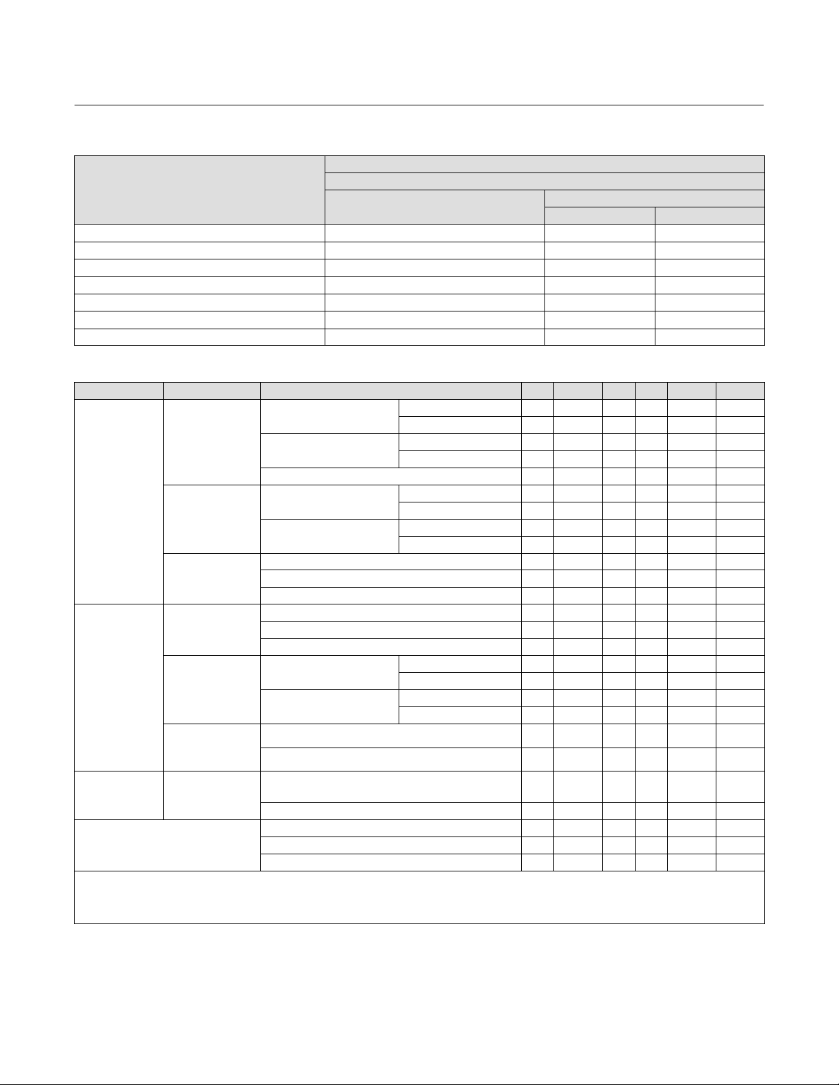
This safety manual applies to the DVC6200 SIS instrument with electronics hardware revision 2
(HW2) and firmware revision 4, 5, 6, and 7 with the following product options.
OPTION
MODEL CONSTRUCTION
DVC6200 SIS Integral, Aluminum n n n n n n n n
DVC6200S SIS
DVC6205 SIS
DVC6215
Integral,
Stainless Steel
Remote Mount
Aluminum
DETT ETT 4-20 mA 24 VDC
n n n n n n n n
(1)
,
n n n n n n n n
Double-
Acting
Direct
Single-
Acting
Reverse
Single-
Acting
Direct
Position
Monitor
APPLICATION
DETT n n n n n n n
ETT n n n n n n
4-20 mA n n n n n n n
24 VDC n n n n n n
1. The Remote Mount construction is not available with the DVC6200 SIS High Cv option.
Accessories
LCP100/LCP200Local Control Panel, HART Only
LC340Line Conditioner, 24 VDC
2
Page 3

Instruction Manual Supplement
D103601X012
DVC6200 SIS Digital Valve Controller
February 2022
3. Terms, Abbreviations, and Acronyms
β Beta factor for common cause effects of failure
DD
DETT Deenergize to Trip
DTM
DVC6200 SIS Digital Valve Controller, product model designation for Safety Instrumented System applications
ESD Emergency Shut Down
ETT Energize to Trip
FIT Failure In Time (1x10⁹ failures per hour)
FMEDA Failure Mode Effect and Diagnostic Analysis
HART
HCv1
HCv2
HCv3 Pneumatic booster with an exhaust Cv of 6.2 and a fill Cv of 3.2 for single direct acting.
HFT Hardware Fault Tolerance
λ
LC340
LCP100
LCP200
Low Demand
Mode
Multidrop
PFD
AVG
PointtoPoint Operating mode of the DVC6200 SIS whereby the instrument is powered with 420 mA.
PVST Partial Valve Stroke Test
Relay A
Relay B
Relay C
Safety Freedom from unacceptable risk of harm.
Safety
Function
SFF Safe Failure Fraction
SIF Safety Instrumented Function
SIL Safety Integrity Level
SIS Safety Instrumented System
SOV Solenoid Operated Valve
Type A
Element
Type B
Element
Device Description, an electronic data file that describes specific features and functions of a
device to be used by host applications.
Device driver that provides a unified structure for accessing device parameters, configuring and
operating the devices, and diagnosing problems.
Highway Addressable Remote Transducer, open protocol for digital communication
superimposed over a direct current.
Pneumatic booster with a Cv of 1.2 for double acting and both single direct and reverse acting.
(Note: single-acting reverse certified for ETT applications only.)
Pneumatic booster with a Cv of 3.2 for double acting and both single direct and reverse acting.
(Note: single-acting reverse certified for ETT applications only.)
Failure rate. λDD: dangerous detected; λDU: dangerous undetected; λSD: safe detected; λSU: safe
undetected.
Line Conditioner; product model designation for a device that is inserted in the loop when the
instrument (in Multidrop Mode) is powered with a lowimpedance 24 V source, to enable HARTr
communications.
Local Control Panel; product model designation for a device that can be connected to a DVC6200
SIS instrument to enable manuallyinitiated functions.
Mode of operation of a safety instrumented function where the demand interval is greater than
twice the proof test interval.
Operating mode of the DVC6200 SIS where the instrument controls the current drawn to enable
it to be powered with 24 VDC.
Average Probability of Failure on Demand
Pneumatic booster relay for double or single acting applications. Typical construction for double
acting DETT applications.
Pneumatic booster relay for single acting reverse applications. Typical construction for single
acting ETT applications.
Pneumatic booster relay for single acting direct applications. Typical construction for single
acting DETT applications.
Function of a device or combination of devices intended to be used within a Safety Instrumented
System to reduce the probability of a specific hazardous event to an acceptable level.
“NonComplex” element (using discrete components); for details see 7.4.4.1.2 of IEC 615082.
“Complex” element (using complex components such as micro controllers or programmable
logic); for details see 7.4.4.1.3 of IEC 615082.
3
Page 4

DVC6200 SIS Digital Valve Controller
February 2022
4. Related Literature
D Fisher DVC6200 Series Quick Start Guide (D103556X012)
Instruction Manual Supplement
D103601X012
D Fisher DVC6200 SIS Instruction Manual (D103557X012
D 62.1:DVC6200 SIS, Fisher DVC6200 SIS Product Bulletin (D103555X012
D HART Field Device Specification for Fisher DVC6200 SIS (D103638X012
D Fisher LCP200 Local Control Panel Instruction Manual (D104296X012
D 62.1:LCP200, Fisher LCP200 Local Control Panel Product Bulletin (D104313X012
)
)
)
)
)
D IEC 61508: 2010 Functional safety of electrical/electronic/programmable electronic
safetyrelated systems
D ANSI/ISA 84.00.012004 (IEC 61511 Mod.) Functional Safety – Safety Instrumented Systems for
the Process Industry Sector
D Exida FMEDA Report for Fisher DVC6200 SIS, Position Monitor Applications
Report No. EFC 12/02027 R001
D Exida FMEDA Report for Fisher DVC6200 SIS, DETT and ETT Applications
Report No. EFC 12-02-027 R004 V3 R0
D Exida FMEDA Report for Fisher DVC6200 SIS Digital Valve Controller with High Cv Option, ESD
DETT applications - Report No. EFC 12/02-037 R002 V2 R3
D Exida FMEDA Report for Fisher DVC6200 SIS Digital Valve Controller with High Cv Option, ESD
ETT applications - Report No. EFC 14/03-045 R001 V1 R5
4
Page 5

Instruction Manual Supplement
D103601X012
DVC6200 SIS Digital Valve Controller
5. General Requirements
WARNING
To ensure safe and proper functioning of equipment, users of this document must carefully read all
instructions, warnings, and cautions in this safety manual and the Quick Start Guide.
D Refer to the Fisher DVC6200 SIS Quick Start Guide (D103556X012) for mounting and
configuration.
February 2022
D If a LCP200 is used, refer to the Fisher LCP200 instruction manual (D104296X012
configurations and mounting.
D Tools needed:
DVC6200 SIS
D Flat Head Screwdriver, 3 mm Thin Blade (wiring terminations)
D Phillips Screwdriver
D 3/8” Hex Key (terminal box conduit plug)
D 6 mm Hex Key (module base screws)
D 5 mm Hex Key (terminal box screw)
D 2.5 mm Hex Key (I/P converter screws)
D 1.5 mm Hex Key (terminal box cover screw)
D 9/64” Hex Key (spool valve screws, HCv1)
D 3 mm Hex Key (spool valve screws, HCv2 and HCv3)
LCP200
) for wiring
D Phillips Screwdriver (ground screw)
D Flat Head Screwdriver, 3 mm Thin Blade (wiring terminations)
D 10 mm Hex Key (cable entry plug)
D 4 mm Hex Key (terminal cover screw)
D 2.5 mm Hex Key (LED module screw, front panel screw)
D Torque wrench capable of 2 - 2.5 N•m (18 - 22 lb•in) (terminal cover screw)
D Personnel performing maintenance and testing on the DVC6200 SIS and LCP200 shall be
competent to do so.
5
Page 6

DVC6200 SIS Digital Valve Controller
February 2022
Instruction Manual Supplement
D103601X012
6. Safety Instrumented System Design
When using the DVC6200 SIS digital valve controller or DVC6200 SIS with the LCP200 in a safety
instrumented system, the following items must be reviewed and considered.
6.1 SIL Capability
6.2 Safety Function
6.3 Failure Rates
6.4 Application Limits
6.5 Environmental Limits
6.6 Application of the Switch Output for Diagnostic Annunciation
6.1. SIL Capability
D Systematic Integrity
SIL 3 Capable— the digital valve controller has met manufacturer design process
requirements of IEC 61508 Safety Integrity Level 3.
D Random Integrity
D The digital valve controller is classified as a Type A device according to IEC 61508. The
complete final element subsystem will need to be evaluated to determine the SFF. If the
SFF of the subsystem is >90%, and the PFD
< 103, the design can meet SIL 3 @ HFT=0.
avg
D The position monitor is classified as a Type B device according to IEC 61508. The
complete final element subsystem will need to be evaluated to determine the SFF. If the
SFF of the subsystem is >90%, and the PFD
If the SFF of the subsystem is between 60% and 90%, and the PFD
< 102, the design can meet SIL 2 @ HFT=0.
avg
< 101, the design
avg
can meet SIL 1 @ HFT=0.
D The LCP200 is classified as a Type B device per IEC61508. If the SFF of the relay output
state change subsystem is >90% and the PFD
avg
0. If the SFF of the subsystem is between 60% and 90%, and the PFD
< 10
2,
the design can meet SIL2 @ HFT =
< 101, the design
avg
can meet SIL 1 @ HFT=0.
6
Page 7

Instruction Manual Supplement
D103601X012
DVC6200 SIS Digital Valve Controller
February 2022
6.2. Safety Function
D Deenergize to Trip Application: The application of the digital valve controller is limited for SIS
to low demand mode. Table 1 describes the normal and safe states of DVC6200 SIS for a DETT
configuration. The digital valve controller may be operated with one of the following control
signals:
D 024 VDC: Normal operation is with a 24 VDC signal applied to the digital valve
controller. A shutdown command is issued by interrupting the loop or taking the
voltage signal to 1 VDC or less.
D 420 mA: Normal operation is with a 20 mA current loop signal to the digital valve
controller. A shutdown command is issued by taking the current signal to 4 mA
(nominal). If a looppowered LCP100/LCP200 is attached, the shutdown command is
issued by taking the current signal to 8 mA (nominal).
Table 1. Normal and Safe States for De-Energize to Trip (DETT) Application
Action Output Type
Direct
Single
Reverse
Double Direct
1. DVC6200 SIS High Cv option is not certified for single-acting reverse DETT application.
(1)
Input Voltage or
Current
0 VDC or 4 mA Port A < 1 psi
24 VDC or 20 mA
0 VDC or 4 mA
24 VDC or 20 mA Port B < 1 psi
0 VDC or 4 mA
24 VDC or 20 mA
Normal State Safe State
Port A
≥ 95% of Supply
Output B ≥ Supply
Pressure less 5 psi
Port A pressure
≤ Port B pressure
Port A ≥ 95% of Supply
Port B < 1 psi
D Energize to Trip Application (a less common application): The application of the digital valve
controller is limited for SIS to low demand mode. Normal operation is with a 4 mA current
loop signal to the digital valve controller. If a looppowered LCP100/LCP200 is attached,
normal operation is with an 8 mA (nominal) current loop signal to the digital valve controller.
Table 2 describes the normal and safe states of DVC6200 SIS for an ETT configuration. A
shutdown command is issued by taking the current signal to 20 mA (nominal).
Table 2. Normal and Safe States for Energize to Trip (ETT) Application
Action Output Type Input Current Normal State Safe State
Single Reverse
Double Direct
4 mA Port B ≥ 95% of Supply
20 mA Port B < 1 psi
4 mA
20 mA
Port A < 1 psi
Port B ≥ 95% of Supply
Port A ≥ Port B
pressure
D Position Monitor Application: The safety function of the position transmitter output is to
transmit a 420 mA analog signal that represents valve position. The safety function of the
limit switch output is to transmit a discrete signal that represents a user configurable
7
Page 8

DVC6200 SIS Digital Valve Controller
February 2022
Instruction Manual Supplement
threshold of valve position. Table 3 describes the normal and alarm states of the Position
Monitor function of the DVC6200 SIS.
Table 3. Normal and Alarm States for the Position Monitor Application
Output Function Normal State Accuracy Alarm State
420 mA
Position Transmitter
0/1A
Limit Switch
1. Configurable high or low. Values are per NAMUR NE43. Fail high when the instrument is powered.
2. On loss of loop circuit power, the limit switch will go to the open state.
Actual Valve Position 5%
CLOSED 5% OPEN
>22.5 mA or
<3.6 mA
(1)
(2)
D LCP200
D The LCP200 will respond to a local TRIP button press with a change of state of the Trip
relay output.
D The LCP200 will respond to a local RESET button press with a change of state of the reset
relay output.
6.3. Failure Rates
D103601X012
The failure rate data listed in tables 4, 5, 6, 8, 7, 9, and 10 is only valid for the 15year useful
lifetime of the DVC6200 SIS digital valve controller and the LCP200, when used. The failure rates
will increase after this time period. Reliability calculations based on the data listed in the FMEDA
report for mission times beyond the useful lifetime may yield results that are too optimistic, i.e.
the calculated Safety Integrity Level will not be achieved. When used, the LCP100/LCP200 failure
rates and the LC340 failure rates are to be added to the failure rates of the DVC6200 SIS. These
failure rates assume that the self test shutdowns in the DVC6200 SIS are disabled. Consult the
FMEDA report for a detailed list of the assumptions used in the analysis.
Table 4. Failure Rates for DVC6200 SIS with 024 VDC or 420 mA Control Signal, DETT
Failure Rate (in FIT)
DVC6200 SIS
Failure
Category
Fail Safe
Detected
Fail Safe
Undetected
Fail Dangerous
Detected
Fail Dangerous
Undetected
No Effect 1,060 1,636 884 1,460 27 - - Annunciation
Failure Detected
Annunciation
Failure
Undetected
1. This number can be subtracted from the annunciated failure undetected number when the DVC6200 SIS is configured to perform a SOV test.
Double Acting, Single
Acting, Direct Acting
w/PVST
Diagnostics
182 0 182 - - - - 62
143 325 132 314 29 34 19 0
72 0 103 - - - - -
44 117 52 155 1 2 - -
398 0 398 - - - - -
177 0 177 - - - - 62
Normal
Single Acting,
Reverse Acting
w/PVST
Diagnostics
Normal LCP100 LCP200
Adders for LCP Loop or
24V External Power
Non-Interfering
LC340
SOV
Test
Config.
(1)
8
Page 9

Instruction Manual Supplement
D103601X012
DVC6200 SIS Digital Valve Controller
February 2022
Table 5. Failure Rates for DVC6200 SIS High Cv Option with 024 VDC or 420 mA Control Signal, DETT
Failure Rate (in FIT)
Failure
Category
Fail Safe
Detected
Fail Safe
Undetected
Fail Dangerous
Detected
Fail Dangerous
Undetected
No Effect 797 1380 828 1411 27 - Annunciation
Failure
Detected
Annunciation
Failure
Undetected
Double Acting Single Acting, Direct Non-Interfering
w/PVST
Diagnostics
641 0 637 0 - - -
215 455 215 451 29 34 19
140 0 116 0 - - -
38 178 35 151 1 2 -
- - - - - - -
- - - - - - -
DVC6200 SIS High Cv Option
Normal
w/PVST
Diagnostics
Normal LCP100 LCP200
Adders for LCP Loop or
24V External Power
LC340
Table 6. Failure Rates for DVC6200 SIS with 420 mA Control Signal, ETT
Failure Rate (in FIT)
Failure Category
w/PVST Diagnostics Normal
Fail Safe Detected 60 0 0 - 62
Fail Safe Undetected 104 164 28 34 0
Fail Dangerous Detected 261 0 0 - Fail Dangerous Undetected 93 352 2 2 No Effect 939 1,547 27 - Annunciation Failure Detected 425 0 0 - Annunciation Failure Undetected 183 0 0 - 62
1. This number can be subtracted from the annunciated failure undetected number when the DVC6200 SIS is configured to perform a SOV test.
DVC6200 SIS
Adders for LCP Loop or
24V External Power
Non-Interfering
LCP100 LCP200
SOV Test
Config.
(1)
9
Page 10

DVC6200 SIS Digital Valve Controller
February 2022
Instruction Manual Supplement
D103601X012
Table 7. Failure Rates for DVC6200 SIS High Cv Option with 420 mA Control Signal, ETT
Failure Rate (in FIT)
DVC6200 SIS High Cv Option
Failure
Category
Fail Safe
Detected
Fail Safe
Undetected
Fail Dangerous
Detected
Fail Dangerous
Undetected
Double Acting
Single Acting, Direct
w/PVST
Diagnostics
Normal
Single Acting, Reverse Non-Interfering
w/PVST
Diagnostics
Normal LCP100 LCP200
514 0 512 0 0 -
67 155 65 151 28 34
348 0 326 0 0 -
93 441 91 417 2 2
No Effect 802 1418 830 1446 27 Annunciation
Failure
- - - - 0 -
Detected
Annunciation
Failure
- - - - 0 -
Undetected
Adders for LCP Loop or
24V External Power
Table 8. Failure Rates for DVC6200 SIS Position Monitor
Failure Rate (in FIT)
Failure Category
End Mounted Rotary LinkageLess,
NonContact Feedback
Fail Safe Undetected 30 92
Fail Dangerous Detected
Fail Detected (detected by internal diagnostics)
Fail High (detected by logic solver)
Fail Low (detected by logic solver)
(1)
(1)
(1)
Fail Dangerous Undetected 31 96
No Effect 167 258
Annunciation Failure Undetected 5 5
1. If the system is not able to detect any or all of these failure categories, the corresponding Failure Rate(s) must be applied to the Fail
Dangerous Undetected category.
Position Transmitter or Limit Switch
All Other Mountings
160 203
30 30
141 141
10
Page 11
Instruction Manual Supplement
D103601X012
DVC6200 SIS Digital Valve Controller
February 2022
Table 9. Failure Rates for LCP200
Failure Rate (in FIT)
Failure Category
24 VDC External Power
LCP200 Trip and Reset Relay Output
Loop Power
DETT ETT
Fail Safe Undetected 31 31 31
Fail Safe Detected 15 17 15
Fail Dangerous Detected 153 136 148
Fail Dangerous Undetected 17 14 15
No Effect 1320 1338 1328
Annunciation Failure Detected 17 17 17
Annunciation Failure Undetected 8 9 9
Table 10. Failure Rates According to IEC 61508 in FIT
Application Model Device l
w/PVST Diagnostics 581 143 72 44 - 62%
Normal 0 325 0 116 - w/PVST Diagnostics 581 124 103 52 - 66%
Normal 0 306 0 155 - -
(4)
w/PVST Diagnostics 637 215 116 35 - 77%
Normal 0 451 0 151 - w/PVST Diagnostics 641 215 140 38 - 79%
Normal 0 455 0 178 - -
DeEnergize
to Trip
DVC6200 SIS
DVC6200 SIS
High Cv option
DVC6200 SIS /
DVC6200 SIS
High Cv option
Relay A Double,
Single Acting, Relay C
Relay B Single,
Reverse Acting
Adder for SOV Test Config.
Single Acting, Direct
Double Acting
Adder for LCP100 0 29 0 1 - Adder for LCP200 - Non-interfering 0 34 0 2 - Adder for LC340 0 19 0 0 - -
SDlSU
62 0 0 0 - -
(1)
lDDl
DU
w/PVST Diagnostics 485 104 261 93 - 74%
Normal 0 164 0 352 - Adder for SOV Test Config.
Double Acting,
Single Acting, Direct
Single Acting, Reverse
(4)
62 0 0 0 - w/PVST Diagnostics 514 67 348 93 - 79%
Normal 0 155 0 441 - w/PVST Diagnostics 512 65 326 91 - 78%
Normal 0 151 0 417 - -
Adder for LCP100 0 28 0 2 - -
Energize to
Trip
DVC6200 SIS
DVC6200 SIS
High Cv option
DVC6200 SIS /
DVC6200 SIS
Adder for LCP200 - Non-interfering 0 34 0 2 - -
End Mounted Rotary LinkageLess,
NonContact Feedback
0 30 331 31 92.2% 91%
All Other Mountings 0 92 374 96 82.9% 80%
Position
Monitor
High Cv option
DVC6200 SIS
Trip and Reset relay, 24V external power 31 31 153 17 92.7% 90.0%
LCP200
Trip and Reset relay, Loop power, ETT 31 31 147 15 93.3% 90.7%
Trip and Reset relay, Loop power, DETT 31 31 136 14 93.5% 90.7%
1. The No Effect failures are no longer included in the Safe Undetected failure category according to IEC 61508, ed2, 2010.
2. Safe Failure Fraction needs to be calculated on (sub)system level.
3. Diagnostic coverage (DC) is λ
4. This number can be subtracted from the annunciated failure undetected number when the DVC6200 SIS is configured to perform a SOV test.
DD
/ (λ
DD + λDU
)
SFF
(2)
DC
(3)
11
Page 12

DVC6200 SIS Digital Valve Controller
February 2022
Instruction Manual Supplement
D103601X012
6.4. Application Limits
D Safety Instrumented Function design verification must be done for the entire collection of
equipment used in the Safety Instrumented Function including the DVC6200 SIS digital valve
controller and the LCP200 local control panel. The SIS must fulfill the requirements according
to the Safety Integrity Level, especially the limitation of average Probability of Failure on
Demand (PFDavg)
D In order to achieve the published failure rate and classification type for the 420 mA device,
the hardware shutdown function must be enabled. See figure 1.
D The system’s response time is dependent on the entire final element subsystem. The user
must verify the system response time is less than the process safety time for each final
element.
D The DVC6200 SIS digital valve controller fault reaction time is determined by the partial valve
stroke test interval plus the mean time to repair.
D The DVC6200 SIS position monitor safety function has a fault reaction time of 30 seconds
plus the mean time to repair.
D The position monitor with the remote mount construction is not safety certified.
D The LCP200 relay output changing state safety function has a fault reaction time of 180
seconds plus the mean time to repair.
D The valve actuation means must be of a type that automatically moves the valve to the safe
state when the digital valve controller achieves the safe state. Valve stroke timing under these
conditions may also need to be considered as part of the SIS design.
D When using the DVC6200 SIS in redundant applications, the owneroperator of the facility
should institute common cause training and more detailed maintenance procedures
specifically oriented toward common cause defense.
D An estimate for the common cause failure rate (b) as determined for the DVC6200 SIS used in
a redundant configuration is 2% for DETT and ETT applications and 5% for Position Monitor
applications.
D An estimate for the common cause failure rate (b) as determined for the LCP200 used in a
redundant configuration is 5% for the relay output changing state.
D The digital valve controller safety function is intended for use in an independent SIF loop from
the position transmitter or limit switch application. Common cause failures between the
digital valve controller and position monitor were not considered as a part of the FMEDA
analysis.
D The LCP200 is non-interfering to the DVC6200 SIS, meaning that it cannot adversely affect
the safety function of the DVC6200 SIS.
D The supply pressure must not exceed 145 psig. The supply medium may be air or natural gas.
12
Page 13

Instruction Manual Supplement
D103601X012
DVC6200 SIS Digital Valve Controller
Air: Supply pressure must be clean, dry air that meets the requirements of ISA Standard
7.0.01.
Natural Gas: Natural Gas must be clean, dry, oilfree and noncorrosive.
A maximum 40 micrometer particle size in the air system is acceptable. Further filtration
down to 5 micrometer particle size is recommended.
D Diagnostic annunciation is dependent on a HART communicating host device being
connected to the DVC6200 SIS and being able to annunciate any problems encountered
including the absence of a valid response from the DVC6200 SIS.
6.5. Environmental Limits
D Operating ambient temperature, refer to:
February 2022
D DVC6200 SIS Instruction Manual (D103557X012
D LCP200 Local Control Panel Instruction Manual (D104296X012
)
)
D Humidity: tested per IEC 61514-2
D Electromagnetic Compatibility:
D EN 61326‐1:2013 Electrical equipment for measurement, control and laboratory use -
EMC requirements - General requirements
D Immunity ‐ Industrial locations per Table 2 of EN 61326-1
D Emission – Class A, Group 1 per Table 4 of CISPR 11
D To achieve the compatibility, the following installation practices shall be followed
D Metal conduit shall be used to shield the AUX cable between DVC6200 SIS and
LCP200. Ensure that the metal conduit has good contact with the enclosure of each
equipment.
D Both DVC6200SIS and LCP200 enclosures shall be grounded locally.
D Vibration: tested per ANSI/ISA S75.13.01 Section 5.3.5. If excessive vibration can be
expected, special precautions shall be taken which may include, but are not limited to:
D Ensuring the integrity of the instrument mounting to the actuator.
D Ensuring the integrity of pneumatic connections.
D Remote mounting the DVC6200 SIS on a pipestand or wall.
D LCP200 pipe stand or wall mounted.
6.6. Application of the Switch Output for Diagnostic Annunciation
When using the Failure Rates “with PVST Diagnostics”, the system must be capable of monitoring
the DVC6200 SIS for alert conditions. To monitor the diagnostic detection, configure the switch
output to report an alert condition.
13
Page 14
DVC6200 SIS Digital Valve Controller
February 2022
Instruction Manual Supplement
D103601X012
Make sure that the electronics hardware is configured for the switch output.
See figure 1.
With a user interface tool, configure the switch output to report “SIS Diagnostic Credit”
Table 11 lists the diagnostics that are included in the SIS Diagnostic Credit Alert.
Configure the switch to close on detection of an alert.
7. Installation & Commissioning Guidelines
7.1. DVC6200 SIS DETT or ETT Safety Function
Verify that the DVC6200 SIS is suitable for use in this Safety Instrumented Function. If a
LCP200 is being used, verify it is also suitable for the Safety Instrumented Function.
Verify that nameplate markings of all the equipment being installed are suitable for the
hazardous location (if required).
Verify appropriate connections to the logic solver are made by referring to the instruction
and safety manual of the logic solver.
For maximum availability and benefit of digital valve controller features, the unit must be
properly configured and calibrated, the Instrument Mode set to In Service, End Point Pressure
Control (EPPC) enabled, and the protection set to Config & Calib using the Instrument Setup >
Change Protection menu. With protection set, calibration and other protected parameters
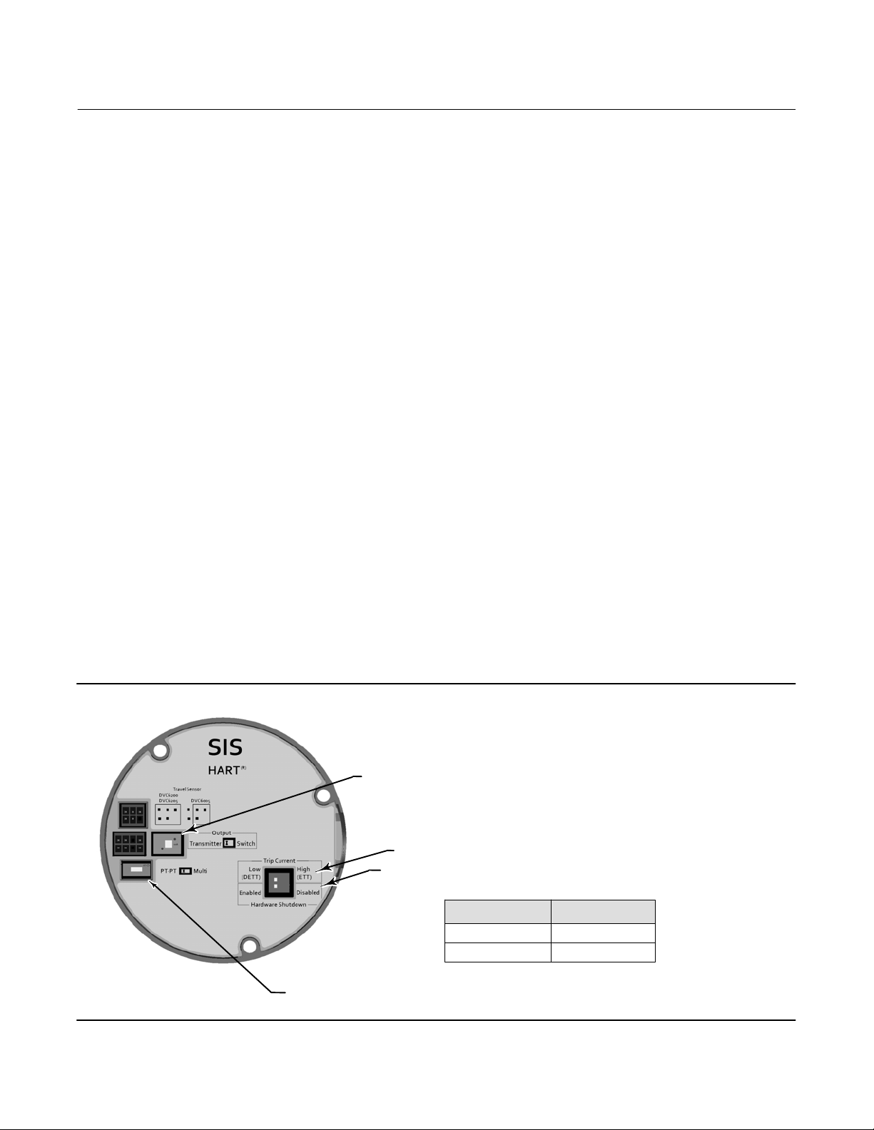
cannot be changed, including the Instrument Mode. Figure 1 below identifies toggle switches
on the main electronics board that are configured as determined by the safety function and
system application.
Figure 1. Configuration Toggle Switches on the Main Electronics Board
POSITION TRANSMITTER / LIMIT SWITCH OUTPUT
DE-ENERGIZE TO TRIP / ENERGIZE TO TRIP SELECTION
HARDWARE SHUTDOWN ENABLE / DISABLE
CONTROL SIGNAL CONFIGURATION
0-24 VDC
4-20 mA
X0436
POINT-POINT / MULTIDROP SELECTION
Multi
PT-PT
14
Page 15

Instruction Manual Supplement
D103601X012
DVC6200 SIS Digital Valve Controller
February 2022
When operating with a 024 VDC control signal, the Hardware Shutdown circuit must be
“Disabled” and an LC340 line conditioner is required to allow HART communication. An
impedance boosting multiplexer (available from MTL, Pepperl+Fuchs / Elcon and others) may
be used in place of the LC340. Refer to the documentation that comes with the product for
installation instructions.
An LCP100/LCP200 local control panel may be connected to the DVC6200 SIS to manually
operate the final control element or run a PVST. Additionally, the LCP200 can change the
state of the relay output when the trip or reset button is pressed. For details, see section 7.3
below. Both the LCP100 and LCP200 are noninterfering devices when used in DETT
applications; the LCP200 is also non-interfering in ETT applications. The LCP200 has two
safety functions available for use. Refer to table 4, 5, 6, 8, 7, 9, and 10 for failure rate adders
when using the LCP100/LCP200. Refer to the documentation that comes with the product
and LCP100/LCP200 instruction manual for installation and safety instructions.
The safety function of the DVC6200 SIS within the final control element subsystem along
with the overall SIS safety function must be tested after installation to ensure that it meets
safety demand and applicable process safety time requirements.
Solenoid Valve Test (not supported by DVC6200 SIS High Cv Option) - When a solenoid valve
is installed in the pneumatic path between the digital valve controller pressure output and the
actuator input, the digital valve controller can be configured to verify the operation of the
solenoid valve. This applies to single-acting actuator applications only. The “unused” output
port of the digital valve controller is tubed such that the pressure downstream of the solenoid
valve is measured. When the solenoid valve is pulsed by the DVC6200 SIS, the digital valve
controller senses the momentary pressure drop across the solenoid valve and records the
data for performance evaluation.
To do this, the OUT terminals in the digital valve controller are used in series with the solenoid
valve and the Transmitter/Switch selection on the printed wiring board must be set to
“Switch”. In addition the Output Terminal must be set to “Solenoid Valve Test”.
7.2. Position Monitor Safety Function
Note
The position monitor (transmitter or switch) with the remote mount construction is not safety certified.
Verify that the DVC6200 SIS with position monitor is suitable for use in this Safety
Instrumented Function.
Verify that nameplate markings are suitable for the hazardous location (if required).
Verify appropriate connections to the logic solver are made by referring to the instruction
and safety manual of the logic solver.
15
Page 16

DVC6200 SIS Digital Valve Controller
February 2022
Instruction Manual Supplement
D103601X012
Ensure that the Output toggle switch (shown in figure 1) is set to the Transmitter position or
Switch position, depending on the application.
Ensure that the device configuration parameter for the function of the output terminal
matches the Output toggle switch setting.
For maximum availability and benefit of digital valve controller features, the unit must be
properly configured and calibrated, the Instrument Mode set to In Service, and the protection
set to Config & Calib using the Instrument Setup > Change Protection menu. With protection
set, calibration and other protected parameters cannot be changed, including the Instrument
Mode. Figure 1 identifies toggle switches on the main electronics board that are configured
as determined by the safety function and system application.
The sensor safety function of the position monitor along with the overall SIS safety function
must be tested after installation to ensure that it meets safety demand and applicable
process safety time requirements.
7.3. LCP200 Trip and Reset Relay Output Safety Function
Verify that the LCP200 trip and reset relay output is suitable for use in this Safety Instrumented
Function.
Verify that nameplate markings are suitable for the hazardous location (if required).
Verify appropriate connections to the logic solver are made by referring to the instruction and
safety manual of the logic solver.
To achieve electromagnetic compatibility, the following installation practices shall be followed.
D Metal conduit shall be used to shield the AUX cable between the DVC6200 SIS and LCP200.
Ensure that the metal conduit has good contact with the enclosure of both equipment.
D Both DVC6200 SIS and LCP200 enclosures shall be grounded locally.
Ensure that the logic solver has the appropriate logic for the desired action on the relay output
change state.
The trip and reset relay output safety function of the LCP200 along with the safety function of
the shutdown valve must be tested after installation to ensure that it meets safety demand and
applicable process safety time requirements.
16
Page 17

Instruction Manual Supplement
D103601X012
DVC6200 SIS Digital Valve Controller
February 2022
8. Operation, Periodic Inspection, Test, and Repair
Periodic testing, consisting of proof tests and partial stroke testing, is an effective way to reduce
the PFD
connected to. Results of periodic inspections and tests should be recorded and reviewed
periodically.
Note
Any time the SIF needs to be disabled, such as to perform a proof test or to take corrective action, appropriate
measures must be taken to ensure the safety of the process.
Note
To ensure corrective action, continuous improvement, and accurate reliability prediction, the user must also work
with their local Emerson Automation Solutions service representative to see that all failures are reported.
8.1. Test Steps for the DVC6200 SIS, Position Monitor, and LCP200
of the DVC6200 SIS instrument, LCP200 as well as the valve and actuator it is
avg
Proof tests are fullstroke tests that are manually initiated. As part of the test, the capability of the
SIF to achieve the defined safe state must be verified. The proof test interval must be established
for the SIF based on the failure rates of all the elements within the function and the risk reduction
requirements. The proof test interval has to be at least 2 times more frequent than the demand
rate. This determination is a critical part of the design of the SIS. For the DVC6200 SIS with
pneumatic relay a proof test will detect 77% (ETT) to 79% (DETT) of dangerous undetected failures
not detected by the DVC6200 SIS automatic diagnostics. For High Cv option a proof test will
detect 80% (ETT) to 81% (DETT, Single Acting Direct) or 83% (DETT, Double Acting) of dangerous
undetected failures not detected by the DVC6200 SIS automatic diagnostics. A proof test includes
the following steps:
Read the digital valve controller alert record using a HART communicating device such as a
Device Communicator, ValveLink software or a DD or DTM based host. Any active alert
messages must be investigated and resolved.
Bypass the final control element or take appropriate action to avoid a false trip.
If used, bypass the safety function of the position monitor or take appropriate action to avoid
a false trip.
If applying “with PVST” failure rates, verify that the Instrument Mode is In Service, End Point
Pressure Control (EPPC) is enabled, and that the instrument Protection is set to Config &
Calib.
Trip the DVC6200 SIS to its safe state by either deenergization (for DETT) or energization (for
ETT).
Observe that the actuator and valve move to its safe state within the required safety time
through an instrument independent means (visual or other).
17
Page 18

DVC6200 SIS Digital Valve Controller
February 2022
Instruction Manual Supplement
D103601X012
If used, observe that the position transmitter reports the actual valve position to within 5%
accuracy throughout the range of travel as required by the application through an
instrumentindependent means (visual or other).
If used, observe that the limit switch is open through an instrumentindependent means
(visual or other).
Restore the DVC6200 SIS to its normal state by either energization (for DETT) or
deenergization (for ETT).
Observe that the actuator and valve return to its normal state through an
instrumentindependent means (visual or other).
If applying “with PVST” failure rates, ensure that EPPC is operational by noting that output
pressure from the instrument goes to the Pressure Set Point after the Pressure Saturation
Time has elapsed (default 45 seconds).
If used, observe that the position transmitter reports the actual valve position to within 5%
accuracy throughout the range of travel as required by the application through an
instrumentindependent means (visual or other).
If used, observe that the limit switch is closed through an instrumentindependent means
(visual or other).
Check air filters to ensure they are clean and operating properly.
Inspect the unit for any loose screws or other incorrect mechanical condition.
Record the test results and any failures in your company’s SIF inspection database.
Remove the bypass and restore normal operation.
Partial stroke tests are designed to provide Diagnostic Coverage for many of the failure modes of
the final control element without affecting the process under control. To take credit for the “with
PVST” failure rates, the user must ensure that partial stroke tests are performed at least 10 times
more frequently than the expected demand rate. A partial stroke test can be configured to be
initiated by the following means:
D Schedule a partial stroke test to occur automatically on a time schedule (requires
configuration).
D Press the “test” button on the LCP100/LCP200.
D Short the “aux” terminals on the DVC6200 SIS for 3 to 10 seconds (requires configuration).
D Initiate a partial stroke test using the Device Communicator, ValveLink software or a DD or
DTM based host.
Should alarms, alerts, or failures be detected during operation, maintenance or periodic
inspection and test, record the alarms, alerts, or failures, and immediately take corrective action.
To ensure corrective action, continuous improvement, and accurate reliability prediction, the user
18
Page 19

Instruction Manual Supplement
D103601X012
DVC6200 SIS Digital Valve Controller
February 2022
must also work with their local Emerson Automation Solutions service representative to see that
all failures are reported. Table 11 shows the diagnostics that are used to calculate the detected
failure rates.
Table 11. Assumed Diagnostics for Determining Failure Rates Labeled “with PVST”
HART Command 48
(1)
Alert Name Description
Byte 0, Bit 7 Flash Integrity Failure The flash ROM is corrupted. Alert
The pneumatic relay position reading is out of
Byte 0, Bit 6 Minor Loop Sensor Alert
Byte 0, Bit 5 Reference Voltage Failure
Byte 0, Bit 4 Drive Current Failure
Byte 0, Bit 3 Critical NVM Failure
Byte 0, Bit 2 Temperature Sensor Failure
Byte 0, Bit 1 Pressure Sensor Failure
Byte 0, Bit 0 Travel Sensor Failure
Byte 1, Bit 2 SIS Program Flow Failure
Byte 2, Bit 7 SIS Hardware Failure
Byte 2, Bit 6 NonCritical NVM Alert
Byte 3, Bit 6
Byte 3, Bit 4
Valve Stuck (Fw 4, 5, & 6)
PST Abnormal (Fw 7)
End Point Pressure
Deviation Alert
Byte 4, Bit 3 Travel Deviation Alert
Byte 4, Bit 0 Drive Signal Alert
(3)
the valid range.
The electronics has detected a problem with
the internal voltage reading.
The I/P converter should be flowing current, but
is not.
Data is corrupted in the critical section of
configuration memory.
The temperature sensor is reporting a
temperature <60C or >100C.
One or more pressure sensors is outside the
expected operating range.
The travel sensor signal is outside the expected
operating range.
The firmware is not performing the expected
series of calculations.
A demand has occurred, but the electronics
hardware failed to take control of the I/P drive.
Data is corrupted in the noncritical section of
configuration memory.
A PVST has failed. Alert
The instrument is in pressure control and the
pressure is not tracking the set point within the
configured deviation allowance.
The valve travel is not tracking the set point
within the configured deviation allowance.
The controller servo output is out of the normal
operating range.
Byte 5, Bit 2 Output Circuit Error The output circuit is not responding. Alert
LCP Communication failed due to electronics
Byte 5, Bit 3 LCP Communications Error
failure, broken connection or loss of power at
the LCP
Device Status, Bit 2 Analog Input Saturated
1. HART host must be configured to read these alerts and annunciate them.
2. This alert can be independently enabled to force the DVC6200 SIS output to the safe state (shutdown on alert - enabled).
Minor Loop Sensor Alert is not relevant for the DVC6200 SIS High Cv option.
3.
The loop current reading is out of the normal
operating range.
Digital Valve
Controller Action
(2)
(2)
Alert
(2)
Alert
(2)
Alert
(2)
Alert
(2)
Alert
(2)
Alert
(2)
Alert
(2)
Alert
(2)
Alert
Alert
Alert
Alert
Alert
Alert
Alert
Within table 11, the diagnostics detection time for the failures that can affect the safety function
of the DVC6200 SIS instrument is 15 seconds.
The diagnostics detection time for all failures including the PVST is determined by the PVST
interval which is configured by the user.
19
Page 20

DVC6200 SIS Digital Valve Controller
February 2022
Instruction Manual Supplement
D103601X012
8.2. Test Steps for the Position Monitor
Proof tests are fullstroke tests that are manually initiated. As part of the test, the capability of the
SIF to achieve the defined safe state must be verified. If the Position Monitor is used, the Safety
Function must be verified. The proof test interval must be established for the SIF based on the
failure rates of all the elements within the function and the risk reduction requirements. This
determination is a critical part of the design of the SIS. A proof test will detect 88% of dangerous
undetected failures not detected by the DVC6200 SIS automatic diagnostics. A proof test includes
the following steps:
D Proof Test for the Position Transmitter
Bypass the safety function of the position transmitter or take appropriate action to avoid a
false trip.
Using the Device Communicator, ValveLink software or a DD or DTM based host, verify that
the DVC6200 SIS instrument mode is “In Service” and that the instrument protection is set to
“Config & Calib.”
Inspect the feedback elements for any loose screws or other incorrect mechanical condition.
Change the valve position away from it’s current state by more than 5% throughout the range
of travel as required by the application.
Observe that the position transmitter reports the actual valve position to within 5% accuracy
throughout the tested range of travel through an instrumentindependent means (visual or
other).
Restore the valve to its normal state.
Observe that the position transmitter reports the actual valve position to within 5% accuracy
through an instrumentindependent means (visual or other).
Record the test results and any failures in your company’s SIF inspection database.
Remove the bypass and restore normal operation.
D Proof Test for the Limit Switch
Bypass the safety function of the limit switch or take appropriate action to avoid a false trip.
Using the Device Communicator, ValveLink software or a DD or DTM based host, verify that
the DVC6200 SIS instrument mode is “In Service” and that the instrument protection is set to
“Config & Calib.”
Inspect the feedback elements for any loose screws or other incorrect mechanical condition.
Change the valve position such that the limit switch trip point is exceeded.
20
Page 21

Instruction Manual Supplement
D103601X012
DVC6200 SIS Digital Valve Controller
February 2022
Observe that the limit switch changed to the open state within 5% of the trip point through
an instrumentindependent means (visual or other).
Restore the valve to its normal state.
Observe that the limit switch changed to the closed state within 5% of the trip point through
an instrumentindependent means (visual or other).
Record the test results and any failures in your company’s SIF inspection database.
Remove the bypass and restore normal operation.
D Test Steps for the SOV Test
Solenoid valve test is designed to detect a solenoid valve state change by monitoring the
actuator pressure change. The solenoid valve test can be initiated as an independent test or as a
test to be run before a PVST.
Configure the instrument to run a SOV test before a PVST.
Initiate an independent SOV test using an Emerson handheld communicator or ValveLink
software. If predetermined thresholds are violated the SOV test is marked as abnormal and a
PVST abnormal is flagged, if configured. An abnormal SOV test needs to be reviewed and
corrective action initiated.
8.3. Test Steps for the Trip and Reset Relay Output
Proof tests are manually initiated to verify the ability of the SIF to achieve the defined safe state. If
the relay output safety function is used, then they must be periodically verified. The proof test
interval must be established for the SIF based on the failure rates of all the elements within the
function and the risk reduction requirements. This determination is a critical part of the design of
the SIS. A proof test includes the following steps:
D Proof Test for the relay output
Verify that either the green, red or yellow light are illuminated. If none of the lights are
illuminated, then confirm that the LCP200 is communicating to the DVC6200 SIS.
Bypass the safety function of the trip relay output state change and take appropriate action
to avoid a LCP initiated trip by the DVC6200 SIS.
Push the trip button and verify that the trip relay output changed state.
Bypass the safety function of the reset relay output state change and take appropriate action
to avoid a LCP initiated reset by the DVC6200 SIS.
Push the reset button and verify that the reset relay output changed state.
Visually inspect the LCP200 for any damage or contamination.
21
Page 22

DVC6200 SIS Digital Valve Controller
February 2022
Instruction Manual Supplement
Record the test results and any failures in your company’s SIF inspection database.
Remove the bypass and restore normal operation.
8.4. Maintenance
D The effective time to repair the DVC6200 SIS is approximately 2 hours. This comprises of
disassembly, repair, reassembly, and recalibration. This value can be used to determine the
total mean time to restore (MTTR).
D Digital valve controller preventive maintenance consists, at a minimum, of replacing all
critical elastomeric seals and diaphragms in the device and a visual inspection of moving
components to verify satisfactory condition. The SIS Preventive Maintenance Kit includes all
elastomeric seals and diaphragms and is available through your local Emerson sales office.
Following maintenance, the digital valve controller must be calibrated per the Auto Travel
Calibration or Manual Travel Calibration menu. After calibration, the digital valve controller
functional safety must be validated.
D103601X012
D A conservative approach is taken in estimating the service interval for the digital valve
controller in Safety Instrumented Systems. For SIS applications, preventive maintenance
must be performed on the digital valve controller at eight to ten year intervals from the date
of shipment. If the instrument is exposed to the upper or lower extremes of the
environmental limits, the interval for preventative maintenance may need to be reduced.
D The effective time to repair the LCP200 is 1 hour.
D Preventive maintenance of the LCP200 involves replacing the elastomer O ring seals using
the soft parts kit. The LEDs can be replaced by ordering the LCP replacement kit. The
pushbuttons can be replaced using a front panel kit. The electronics can be replaced at a
Fisher authorized service center.
D When the LCP200 safety function is utilized, preventive maintenance must be performed
when the digital valve controller is being taken out for preventive maintenance or 8 to 10
years from the date of shipment of the device. If the instrument is exposed to the upper or
lower extremes of the environmental limits, the interval for preventative maintenance may
need to be reduced.
22
Page 23

Instruction Manual Supplement
D103601X012
DVC6200 SIS Digital Valve Controller
February 2022
9. Decommissioning Guidelines
When decommissioning a DVC6200 SIS instrument, proper procedures must be followed.
Decommissioning includes the following steps:
Bypass the final control element or take appropriate action to avoid a false trip.
Bypass the safety function of the position monitor or take appropriate action to avoid a false
trip.
Bypass the safety function of the LCP200 and take appropriate action to avoid a false trip or
triggering any interlocks in the logic solver.
Avoid personal injury or property damage from sudden release of process pressure or
bursting of parts. Before proceeding with any decommissioning procedures:
D Always wear protective clothing, gloves, and eyewear to prevent personal injury or
property damage.
D Do not remove the actuator from the valve while the valve is still pressurized.
D Isolate and disconnect any operating supply lines providing air pressure, electric power,
or a control signal to the DVC6200 SIS. Be sure the actuator cannot suddenly open or
close the valve.
D Use bypass valves or completely shut off the process to isolate the valve from process
pressure. Relieve process pressure from both sides of the valve.
D Vent the pneumatic actuator loading pressure and relieve any actuator spring
precompression.
D Use lock‐out procedures to be sure that the above measures stay in effect while you
work on the equipment.
D Check with your process or safety engineer for any additional measures that must be
taken to protect against process media.
Disconnect the electrical wiring to and from the DVC6200 SIS instrument and the LCP200, if
used.
Disconnect the pneumatic tubing between the DVC6200 SIS instrument and actuator.
Remove the DVC6200 SIS instrument, the LCP200 and the respective mounting parts and
feedback elements from the actuator.
23
Page 24

DVC6200 SIS Digital Valve Controller
February 2022
Instruction Manual Supplement
D103601X012
Neither Emerson, Emerson Automation Solutions, nor any of their affiliated entities assumes responsibility for the selection, use or maintenance
of any product. Responsibility for proper selection, use, and maintenance of any product remains solely with the purchaser and end user.
Fisher, FIELDVUE, and ValveLink are a marks owned by one of the companies in the Emerson Automation Solutions business unit of Emerson Electric Co.
Emerson Automation Solutions, Emerson, and the Emerson logo are trademarks and service marks of Emerson Electric Co.
FieldComm Group.
The contents of this publication are presented for informational purposes only, and while every effort has been made to ensure their accuracy, they are not
to be construed as warranties or guarantees, express or implied, regarding the products or services described herein or their use or applicability. All sales are
governed by our terms and conditions, which are available upon request. We reserve the right to modify or improve the designs or specifications of such
products at any time without notice.
Emerson Automation Solutions
Marshalltown, Iowa 50158 USA
Sorocaba, 18087 Brazil
Cernay, 68700 France
Dubai, United Arab Emirates
Singapore 128461 Singapore
All other marks are the property of their respective owners.
HART is a registered trademark of
www.Fisher.com
24
E 2012, 2022 Fisher Controls International LLC. All rights reserved.
 Loading...