

IM Supplement: Replacing the Controller Assembly (RL2E0X00C12) on the Fisher L2e Electric Level Controller
Fisher IM Supplement: Replacing the Controller Assembly (RL2E0X00C12) on the Fisher L2e Electric Level Controller Manuals & Guides
Page 1

Instruction Manual Supplement
D104022X012
L2e Controller
April 2020
Replacing the Controller Assembly
™
(RL2E0X00C22) on the Fisher
L2e Electric Level
Controller
This supplement contains information on how to replace the complete controller assembly on the L2e controller.
Refer to the L2e instruction manual (D103531X012
other information regarding the L2e electric level controller.
), available from your Emerson sales office or at Fisher.com, for all
WARNING
Always wear protective clothing, gloves, and eyewear when performing any maintenance operations to avoid personal
injury. To avoid personal injury or property damage caused by the release of pressure or process fluid, observe the
following before starting maintenance:
D Provide some temporary means of control for the process before taking the controller out of service.
D Provide a means of containing the process fluid before removing any measurement devices from the process.
D Vent any trapped process pressure.
D Check with your process or safety engineer for any additional measures that must be taken to protect against process
media.
WARNING
For explosionproof applications, disconnect power before installing, servicing or removing electrical components.
Personal injury or property damage from fire or explosion may result if power is not disconnected.
Select junction boxes, wiring and/or cable glands that are rated for the environment of use (such as hazardous location,
ingress protection, and temperature). Failure to use properly rated electrical hardware wiring and/or cable glands can
result in personal injury or property damage from fire or explosion. Wiring connections must be in accordance with local,
regional, and national codes for any given hazardous area approval. Failure to follow the local, regional, and national codes
could result in personal injury or property damage from fire or explosion.
www.Fisher.com
Page 2
L2e Controller
April 2020
Instruction Manual Supplement
D104022X012
Removing the Controller From the Sensor
Refer to figure 1 for key number locations unless otherwise indicated.
1. Disconnect power from any electrical source.
2. Disconnect electrical wiring from switch.
3. Note Span adjustment setting.
4. Slide the hook end of the zero spring (key 7) over and off the controller end of the displacer rod (key 64).
5. Loosen the four controller mounting screws but don't remove.
6. Tap the controller body to loosen gasket.
7. Remove the four controller mounting screws (key 24); discard screws and gasket.
8. Standing in front of the assembly, remove the controller by pulling it down and toward you, away from the sensor,
taking care to clear the nut on the displacer rod.
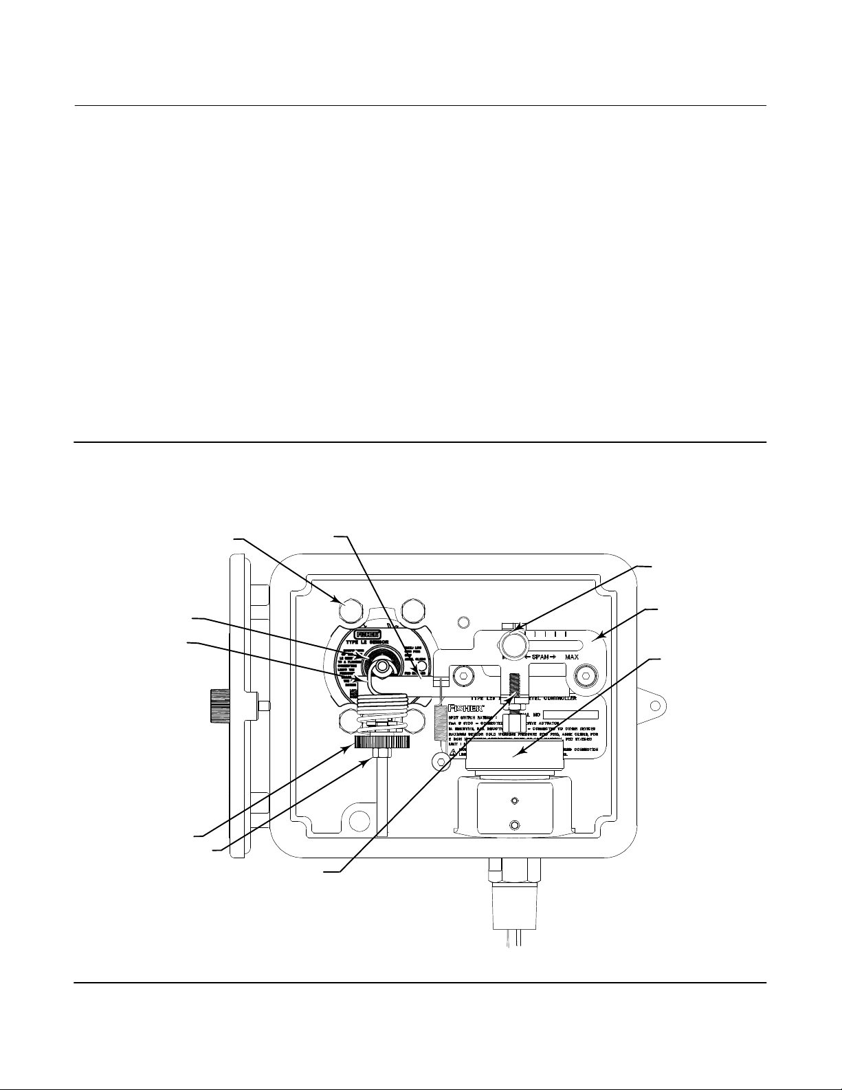
Figure 1. Fisher L2e Controller
CONTROLLER MOUNTING
SCREWS (KEY 24)
DISPLACER
ROD (KEY 64)
ZERO SPRING
(KEY 7)
ZERO ADJUSTMENT
ZERO ADJUSTMENT
HEX NUT (KEY 5)
LEVER A
SPAN
ADJUSTMENT
LEVER B
SWITCH
PLUNGER
FACTORY SET - DO NOT ADJUST
GG10047
w/Displacer Rod
2
Page 3

Instruction Manual Supplement
D104022X012
L2e Controller
April 2020
Replacing the Complete Controller Assembly (RL2E0X00C22)
Refer to figure 1 for key number locations unless otherwise indicated.
1. Install the new controller assembly with new gasket on the sensor. (Make sure lever A is under the displacer rod.)
2. Install the four 1/4-20X1.250”
medium strength thread locking adhesive and a 7/16” socket.
3. Slide the hook end of the zero spring (key 7) onto the controller end of the displacer rod (key 64).
4. Reconnect switch wiring.
5. Reconnect power to electrical source
6. Perform the Initial Setup (Dry or Wet Displacer) and Zero and Span Adjustment procedures below.
cap screws (key 24), supplied in the kit. Torque to 6.8 N•m (60 lbf•in), using
L2e Initial Setup (Dry Displacer)
Refer to figure 2.
1. Move Span to minimum setting.
2. Move Zero down until the valve opens, or N/C contact (red to brown leads) closes.
3. Slowly move Zero up until valve closes, or N/C contact (red to brown leads) opens.
Figure 2. Initial Setup
GG11109-F
3
Page 4

L2e Controller
April 2020
Instruction Manual Supplement
D104022X012
L2e Zero and Span Adjustment (Wet Displacer)
After initial setup (dry displacer) is complete,
1. Enable process flow into the vessel.
2. Move Zero and Span Adjustment for desired liquid zero position (setting noted on previous unit) and level DG
(differential gap).
3. Tighten the Zero Adjustment hex nut (key 5), shown in figure 1, to lock the Zero setting.
Neither Emerson, Emerson Automation Solutions, nor any of their affiliated entities assumes responsibility for the selection, use or maintenance
of any product. Responsibility for proper selection, use, and maintenance of any product remains solely with the purchaser and end user.
Fisher is a mark owned by one of the companies in the Emerson Automation Solutions business unit of Emerson Electric Co. Emerson Automation Solutions,
Emerson, and the Emerson logo are trademarks and service marks of Emerson Electric Co. All other marks are the property of their respective owners.
The contents of this publication are presented for informational purposes only, and while every effort has been made to ensure their accuracy, they are not
to be construed as warranties or guarantees, express or implied, regarding the products or services described herein or their use or applicability. All sales are
governed by our terms and conditions, which are available upon request. We reserve the right to modify or improve the designs or specifications of such
products at any time without notice.
Emerson Automation Solutions
Marshalltown, Iowa 50158 USA
Sorocaba, 18087 Brazil
Cernay, 68700 France
Dubai, United Arab Emirates
Singapore 128461 Singapore
www.Fisher.com
4
E 2015, 2020 Fisher Controls International LLC. All rights reserved.
 Loading...