

Page 1

Instruction Manual
D100433X012
Graphite Packing for Sliding-Stem
Graphite Ribbon/Filament Packing for
™
Fisher
Contents
Introduction 1.................................
Scope of Manual 1.............................
Description 1.................................
Storage and Startup 2...........................
Packing Installation 2...........................
Parts Ordering 7................................
Introduction
Scope of Manual
Sliding‐Stem Valves
July 2017
This manual provides instructions for installing graphite ribbon and filament packing in sliding‐stem valves‐‐either as
part of the field maintenance procedure for valves that originally were equipped with this kind of packing or when
field‐replacing other kinds of packing.
Use this manual along with the appropriate valve body instruction manual. Refer to the valve body manual for
disassembly, packing removal, reassembly after the packing has been installed, and for packing part numbers and kits.
Do not install, operate, or maintain this packing without being fully trained and qualified in valve, actuator, and
accessory installation, operation, and maintenance. To avoid personal injury or property damage, it is important to
carefully read, understand, and follow all the contents of this manual, including all safety cautions and warnings. If you
have any questions about these instructions, contact your Emerson sales office or Local Business Partner before
proceeding.
Description
Graphite ribbon/filament packing is a low‐chloride, corrosion‐resistant packing for use with hard‐to‐handle fluids,
especially high‐temperature steam or water. It can be used in temperatures from -18 to 538_C (0 to 1000_F) in
non‐oxidizing service or from -18 to 371_C (0 to 700_F) in oxidizing service. Because the packing rings are certified to
contain no more than 100 ppm of chloride, this packing is also frequently used in radioactive nuclear service and will
withstand a gamma radiation dosage to 1.0 X 10
Graphite ribbon/filament packing comes in three different arrangements of graphite ribbon rings, graphite filament
rings, and sacrificial zinc washers. The three different arrangements are single (figures 1 and 2), double (figure 3), and
leak‐off (figure 4).
7
Rads or 50 R/hour.
www.Fisher.com
Page 2

Graphite Packing for Sliding-Stem
July 2017
The graphite ribbon rings are made from a long ribbon of flexible graphite which is wound into a ring and then pressed
tightly together. The flexible graphite contains a non‐metallic, inorganic, passivating inhibitor for corrosion and
oxidation resistance. Graphite filament rings consist of filaments of graphite braided together. One sacrificial zinc
washer is used under each graphite ring to protect the valve from pitting and corrosion attack.
Instruction Manual
D100433X012
Storage and Startup
If a valve will be stored for a long period of time, remove the packing rings from the packing box to prevent corrosion.
When ordering a valve that will be stored, notify Emerson Automation Solutions and the valve will be shipped from the
factory with the packing box empty and a special packing follower with O‐ring gland seal installed between the
packing flange and bonnet shoulder. All the other packing parts shown in figure 2, 3, or 4 will be shipped with the
control valve assembly but in a separate bag or wrapper.
Leave the special packing follower in place until after any hydrostatic testing is completed. Then remove the follower,
thoroughly air‐dry the packing box, and install all the packing parts according to the appropriate arrangement
drawing. The special packing follower can be saved for future hydrostatic testing, or discarded if it will no longer be
used.
WARNING
Personal injury could result from packing leakage. Valve packing was tightened prior to shipment; however some
readjustment will be required to meet specific service conditions.
CAUTION
When using any packing at low temperatures, frost must not be allowed to form on the valve stem. Valve stem frost can
damage packing as the stem travels through the packing rings.
Packing Installation
Packing parts are subject to normal wear and must be inspected and replaced as necessary. The frequency of
inspection and replacement of parts depends upon the severity of service conditions or the requirements of local,
state, and federal rules and regulations.
WARNING
Avoid personal injury or property damage from sudden release of process pressure or bursting of parts. Before performing
any maintenance operations:
D Do not remove the actuator from the valve while the valve is still pressurized.
D Always wear protective gloves, clothing, and eyewear when performing any maintenance operations to avoid personal
injury.
D Disconnect any operating lines providing air pressure, electric power, or a control signal to the actuator. Be sure the
actuator cannot suddenly open or close the valve.
2
Page 3

Instruction Manual
D100433X012
Graphite Packing for Sliding-Stem
July 2017
D Use bypass valves or completely shut off the process to isolate the valve from process pressure. Relieve process pressure
from both sides of the valve. Drain the process media from both sides of the valve.
D Vent the pneumatic actuator loading pressure and relieve any actuator spring precompression.
D Use lock‐out procedures to be sure that the above measures stay in effect while you work on the equipment.
D The valve packing box may contain process fluids that are pressurized, even when the valve has been removed from the
pipeline. Process fluids may spray out under pressure when removing the packing hardware or packing rings, or when
loosening the packing box pipe plug.
D Check with your process or safety engineer for any additional measures that must be taken to protect against process
media.
1. Refer to the appropriate valve body and actuator instruction manuals. Disassemble the control valve as required to
gain access to the packing box. Remove the packing box components.
2. Examine the valve stem. The surface that contacts the packing must be smooth and free of scratches and nicks. If
another style of graphite packing had been installed, the packing may have left a black deposit of graphite coating
on the stem. If this deposit has built up or has affected the valve stem finish, the stem should be polished to a 0.1
micro‐meter (4 micro‐inch) RMS finish.
3. Thoroughly clean and dry the packing cavity, valve stem, and all metal packing parts (packing box ring, lantern ring,
and packing follower). Also, clean the threads of the packing flange studs and nuts (figure 1). Lubricate these
threads and the faces of the packing flange nuts during the remainder of the installation with a moly disulfide or
equivalent type of lubricant.
4. Select the correct installation figure reference according to the valve design and packing arrangement (single,
double, or leak‐off).
5. Install the metal packing parts (figures 2, 3, or 4) that go to the bottom of the packing cavity.
WARNING
To avoid valve leakage during operation or personal injury, it is necessary, when installing the packing, to avoid trapping
air between the rings and to give side support to the rings so they do not spread out under the compression of adding more
rings. This may be accomplished by installing only one ring at a time.
6. Install only one packing ring at a time. Push each of the new packing rings into the packing box until it presses
against the ring below it.
If installing double or leak‐off packing, start the last lower packing ring and then force all the lower packing rings and
lantern ring(s) all the way into the packing cavity. Then install the upper packing rings in the same manner.
Figure 1. Typical Single Packing Arrangement Shown Installed in Bonnet
PACKING FLANGE STUD
PACKING FLANGE NUT
PACKING FLANGE
GRAPHITE
FILAMENT
PACKING RINGS
LANTERN RINGS
PACKING BOX
RING
A5507
PACKING FOLLOWER
GRAPHITE RIBBON
PACKING RINGS
SACRIFICIAL ZINC WASHER
3
Page 4
Graphite Packing for Sliding-Stem
July 2017
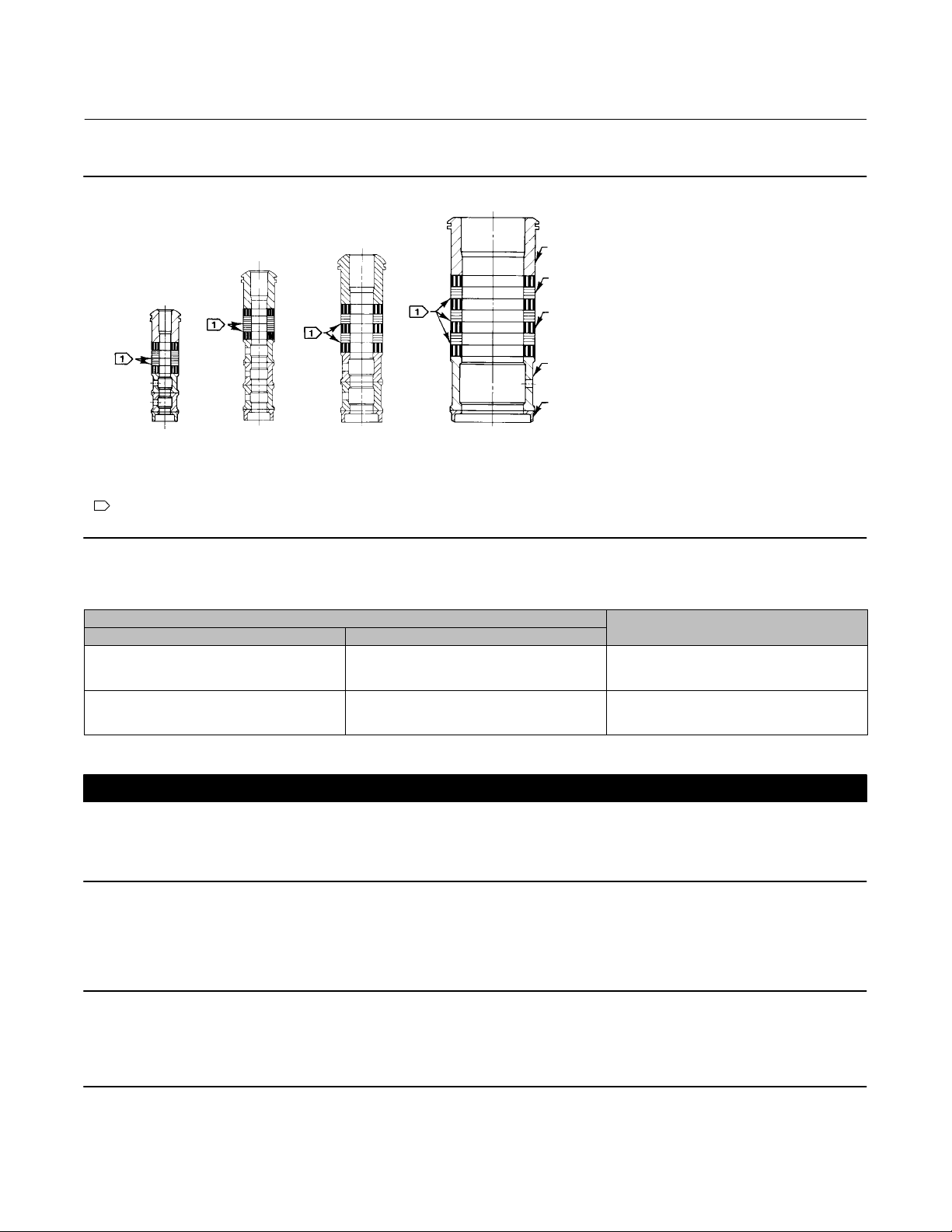
Figure 2. Single Packing Arrangements
Instruction Manual
D100433X012
PACKING FOLLOWER
GRAPHITE RIBBON
PACKING RING
GRAPHITE FILAMENT
PACKING RING
LANTERN RING
14A3411‐A
9.5 mm
(3/8 INCH)
STEM
NOTE:
1
0.102mm (0.004 INCH) THICK SACRIFICIAL ZINC WASHERS;
USE ONLY ONE BELOW EACH GRAPHITE RIBBON RING.
A5513
13A9775‐B
12.7 mm
(1/2 INCH)
STEM
13A9776‐B
19.1, 25.4, & 31.8 mm
(3/4, 1, & 1‐1/4 INCH)
STEM
14A3419‐A
50.8mm
(2‐INCH)
STEM
PACKING BOX
RING
Table 1. Single Packing Arrangements
STEM DIAMETER
mm Inch
9.5
12.7
19.1
25.4
31.8
50.8
3/8
1/2
3/4
1‐1/4
1
2
ARRANGEMENT
ASSEMBLY DRAWING
14A3411
13A9775
13A9776
14A2340
14A3412
14A3419
CAUTION
Loss of packing performance and damage to the valve stem could result if metal parts such as the packing follower come in
contact with the valve stem. When installing packing parts or making packing adjustments, make sure that the inside
diameter of the packing follower does not contact the valve stem.
7. Replace the packing follower, packing flange, and packing flange nuts.
Note
If the packing needs additional tightening after the valve is in service, the packing flange nuts may be tightened to the
recommended maximum torque. Excessive valve stem friction may result if the recommended maximum torque is exceeded. The
recommended minimum torque is necessary to maintain a stem seal.
4
Page 5

Instruction Manual
D100433X012
Figure 3. Double Packing Arrangements
14A2153‐B
9.5 mm
(3/8 INCH)
STEM
NOTE:
1
0.102mm (0.004 INCH) THICK SACRIFICIAL ZINC WASHERS;
USE ONLY ONE BELOW EACH GRAPHITE RIBBON RING.
A5514
14A1849‐B 14A1780‐B
12.7 mm
(1/2 INCH)
STEM
14A3418‐A
19.1, 25.4, & 31.8 mm
(3/4, 1, & 1‐1/4 INCH)
STEM
Graphite Packing for Sliding-Stem
July 2017
PACKING FOLLOWER
GRAPHITE RIBBON
PACKING RING
GRAPHITE FILAMENT
PACKING RING
LANTERN RING
PACKING BOX
RING
50.8mm
(2‐INCH)
STEM
Table 2. Double Packing Arrangements
STEM DIAMETER
mm Inch
9.5
12.7
19.1
25.4
31.8
50.8
3/8
1/2
3/4
1‐1/4
1
2
ARRANGEMENT
ASSEMBLY DRAWING
14A2153
14A1849
14A1780
14A3413
14A3414
14A3418
8. Evenly tighten the packing flange nuts to force the packing rings against the lantern ring(s). Continue to evenly
tighten the nuts until the maximum recommended torque shown in table 4 is reached. Then, loosen the packing
flange nuts and retighten to the recommended minimum torque in table 4.
9. Reassemble the control valve assembly according to the instructions in the appropriate instruction manual.
5
Page 6

Graphite Packing for Sliding-Stem
July 2017
Figure 4. Leak‐Off Packing Arrangements
15A5377‐B
9.5 mm
(3/8 INCH)
STEM
NOTE:
1
0.102mm (0.004 INCH) THICK SACRIFICIAL ZINC WASHERS;
USE ONLY ONE BELOW EACH GRAPHITE RIBBON RING.
A5508
14A3415‐A
12.7, 19.1 mm
(1/2, 3/4 INCH)
STEM
15A5378‐B 15A5472‐A
25.4 mm
(1‐INCH)
STEM
15A7085‐A
31.8 mm
(1‐1/4 INCH)
STEM
Instruction Manual
D100433X012
PACKING FOLLOWER
GRAPHITE RIBBON
PACKING RING
LANTERN RING
GRAPHITE FILAMENT
PACKING RING
PACKING BOX
RING
50.8mm
(2‐INCH)
STEM
Table 3. Leak-Off Packing Arrangements
STEM DIAMETER
mm Inch
9.5
12.7
19.1
25.4
31.8
50.8
3/8
1/2
3/4
1
1‐1/4
2
ARRANGEMENT
ASSEMBLY DRAWING
15A5377
14A2485
14A3415
15A5378
15A7085
15A5472
6
Page 7

Instruction Manual
D100433X012
Graphite Packing for Sliding-Stem
July 2017
Table 4. Recommended Packing Flange Nut Torques
VALVE STEM
DIAMETER
mm Inch NSm LbfSft NSm LbfSft
9.5 3/8
12.7 1/2
15.9 5/8
19.1 3/4
25.4 1
31.8 1‐1/4
50.8 2
1. With lubricated packing flange studs.
VALVE RATING
CL150
CL300
CL600
CL900
CL1500
CL150
CL300
CL600
CL900
CL1500
CL2500
CL150
CL300
CL600
CL150
CL300
CL600
CL900
CL1500
CL2500
CL300
CL600
CL900
CL1500
CL2500
CL300
CL600
CL900
CL1500
CL2500
CL300
CL600
CL900
CL1500
CL2500
(1)
MAXIMUM MINIMUM
5
7
8
10
12
8
10
14
18
22
24
7
8
12
16
20
30
41
50
61
37
50
62
77
91
49
66
83
102
122
65
91
119
146
170
4
5
6
7
9
6
7
10
13
16
18
5
6
9
12
15
22
30
37
45
27
37
46
57
67
36
49
61
75
90
48
67
88
108
125
3
4
5
7
8
5
7
10
12
15
18
4
5
8
11
14
20
27
34
41
24
34
42
52
61
32
45
56
68
81
43
61
80
98
115
2
3
4
5
6
4
5
7
9
11
13
3
4
6
8
10
15
20
25
30
18
25
31
38
45
24
33
41
50
60
32
45
59
72
85
Parts Ordering
Refer to the appropriate valve body instruction manual for all bonnet packing parts.
Determine the parts needed from the appropriate packing arrangement in figures, 2, 3, or 4. Include the serial number
of the valve in all correspondence concerning replacement parts or maintenance.
WARNING
Use only genuine Fisher replacement parts. Components that are not supplied by Emerson Automation Solutions should
not, under any circumstances, be used in any Fisher valve, because they may void your warranty, might adversely affect the
performance of the valve, and could cause personal injury and property damage.
7
Page 8

Graphite Packing for Sliding-Stem
July 2017
Instruction Manual
D100433X012
Neither Emerson, Emerson Automation Solutions, nor any of their affiliated entities assumes responsibility for the selection, use or maintenance
of any product. Responsibility for proper selection, use, and maintenance of any product remains solely with the purchaser and end user.
Fisher is a mark owned by one of the companies in the Emerson Automation Solutions business unit of Emerson Electric Co. Emerson Automation Solutions,
Emerson, and the Emerson logo are trademarks and service marks of Emerson Electric Co. All other marks are the property of their respective owners.
The contents of this publication are presented for informational purposes only, and while every effort has been made to ensure their accuracy, they are not
to be construed as warranties or guarantees, express or implied, regarding the products or services described herein or their use or applicability. All sales are
governed by our terms and conditions, which are available upon request. We reserve the right to modify or improve the designs or specifications of such
products at any time without notice.
Emerson Automation Solutions
Marshalltown, Iowa 50158 USA
Sorocaba, 18087 Brazil
Cernay 68700 France
Dubai, United Arab Emirates
Singapore 128461 Singapore
www.Fisher.com
8
E 1990, 2017 Fisher Controls International LLC. All rights reserved.
 Loading...