

Page 1

Gel Documentation System
Gerix
Installation and Operating
Instructions
BIOTEC-FISCHER GmbH * Daimlerstrasse 6 * 35447 Reiskirchen
Tel: +49-6408-6072 * Fax: +49-6408-64165
e-mail: info@biotec-fischer.de
Page 2

To this means of work:
This manual serves to set up the PC-independent system Gerix correctly.
The operating instructions of the transilluminator and dark hood are available for continuative use.
Seite 2 von 29
Page 3

Directory
1. General information and preparation 4
1.1 Scope of delivery 4
1.2 Preparation for system setup 4
1.3 Setup of dark hood and transilluminator 4
1.4 Setup of basic system Gerix 1000 4
1.5 Connection of b/w-thermal printer Mitsubishi P93E 6
2. Details on safe handling of Gerix 1000 7
2.1 Important safety instructions 7
2.1.1 Important details on system voltage 7
2.1.2 Important details on UV protection 7
2.2 Maintenance 8
3. System specifications 9
4. Insertion process 9
5. Keyboard 10
6. Functions 12
6.1 Live Image Mode 12
6.2 Exposure Mode 13
6.3 Saturation / Mode Automatic Illumination 14
6.4 Invert / Set 16
6.5 Capture Mode 17
6.6 Storage on USB sticks 18
6.7 Print-out of image displayed 20
7. System Settings 21
7.1 Load Settings 22
7.2 Save Settings 23
7.3 Standard Settings 24
7.4 Date Format 25
7.5 Set Time / Date 26
7.6 Setting of key tones and automatic storage 28
7.7 Information 29
8. Contact Details 29
Seite 3 von 29
Page 4

1. General information and preparation
1.1 Scope of delivery
At the beginning, please check the contents according to the delivery note enclosed:
- Control unit of basic system Gerix 1000
- Camera with objective, close-up lens and filter
- Control wire to connect camera and control unit
- 3.5 mm phone jack wire
- Transilluminator e.g. UXT-20M-8K
- Dark hood e.g. DH-30
- Test gel for fluorescence
- 3 power cords
1.2 Preparation for system setup
Completely unpack and unwrap all single elements. It is recommended to place them directly
on a stable surface.
Add the control wire and the power cords to the corresponding components.
1.3 Setup of dark hood and transilluminator
Place the transilluminator UXT-20M-8K with the front showing to you on the working surface.
Make sure that the transilluminator is switched off (switch at the bottom of the front side).
Now, place the dark hood DH-30 on the transilluminator. The sliding door of the dark hood
must be directed to you.
Then, mount the dark hood with 4 hinges on the transilluminator. Please check carefully if
each of the hinges has clicked into place correctly.
Connect the dark hood and the transilluminator each with a power cord and a socket outlet
grounded. The outlets of the components are at the backside. Please check again the
connections before switch-on.
1.4 Setup of basic system Gerix 1000
Please carry out the instructions mentioned below very accurately and conscientiously as it
mainly concerns damageable and optical elements.
1. Screw the objective on the camera. Please pay attention as it concerns a fine thread.
2. Screw the close-up lens on the objective.
3. Screw the filter according your application on the close-up lens.
Seite 4 von 29
Page 5
4. Connect the 12-pin connector of the control wire with the respective connector of the
camera. Please be very careful as no pin may be bent. By correct connection the nut
locks in place with a click.
5. Place the round disc with the centre hole directly on the opening of the dark hood.
Fractionally, move the disc to centre correctly over the round opening.
6. Fix the camera with the screw included to the camera angle of the dark hood. Use
the disc and the rubber mat to achieve light tightness. The respective holes are
adapted to the diameter of filter and objective. The rubber mat is moved over the
objective in the way it fits densely to the metal sheet of the dark hood.
7. Connect the control wire with the 12-pin connector of the control unit. Don’t forget to
screw tight the coupling nut of the connector.
8. Connect the control unit with a socket outlet grounded using a power cord. The
outlet for the power cord is at the back side of the control unit. Please check again
the connections before switching on.
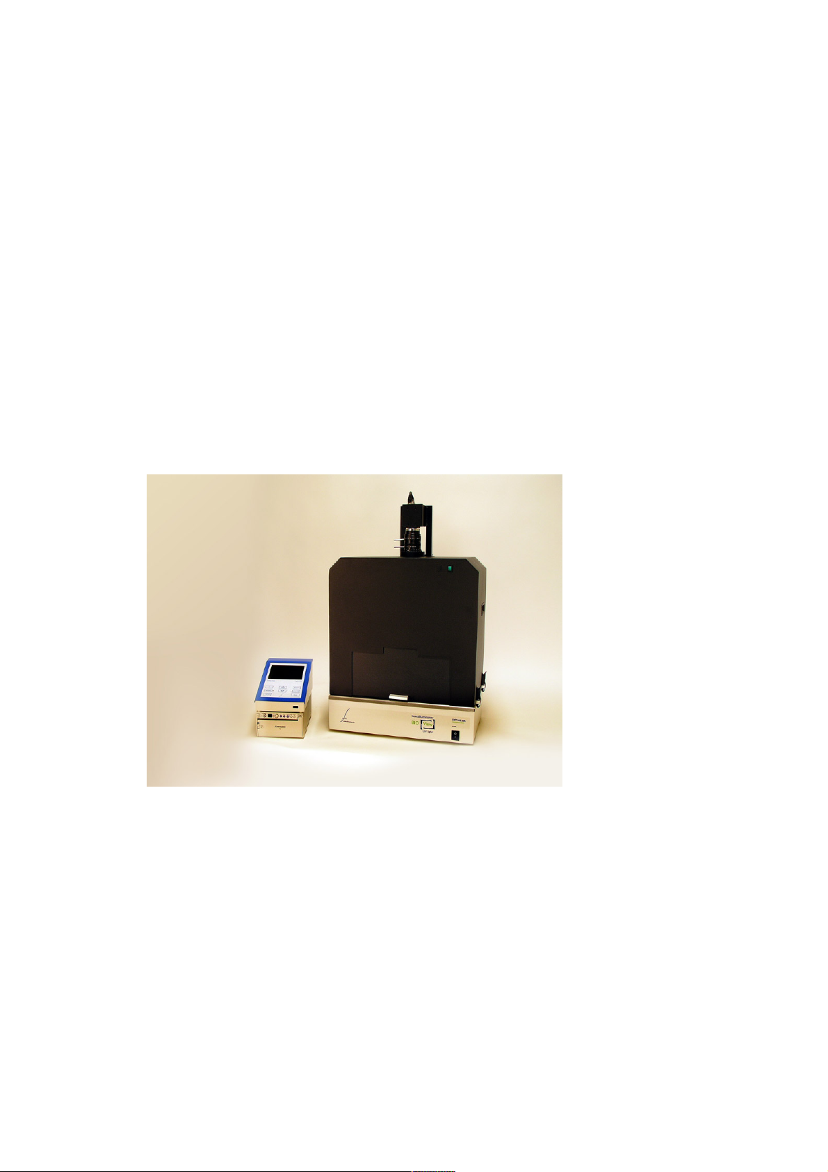
Image 1 System Gerix 1000 completely set up
(with thermal printer P93E, optional available)
Now, the system is ready for operation and can be used to expose gels. At the beginning it is
recommended to work with a test gel included in the commodity.
Seite 5 von 29
Page 6
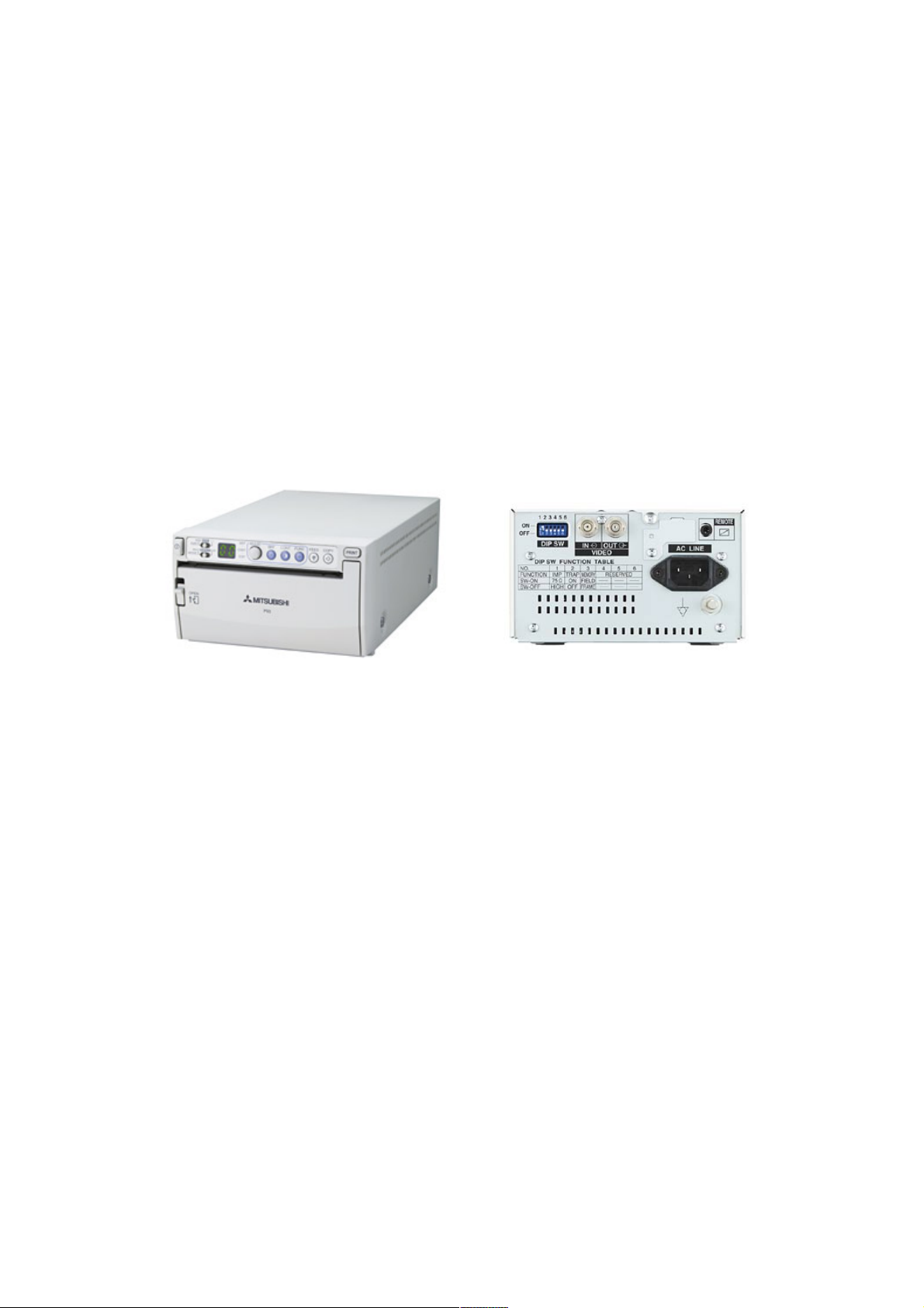
1.5 Connection of b/w - thermal printer Mitsubishi P93E
In case the consignment includes the thermal printer P93E information on the connection
with the system Gerix 1000 are given below:
1. Place the printer below or beside the system Gerix 1000.
2. Connect the BNC connector of the system with the BNC connector „VIDEO IN“ of the
printer using the BNC wire.
3. Connect the 3.5mm jack plug „REMOTE“ of the printer with the 3.5mm jack plug of
the system using the jack plug wire included in the commodity.
4. Connect the printer with the socket outlet using the power cord. The outlet for the
power cord is at the back side of the printer. Please check again the connections
before switching on.
Image 2 b/w – Thermal printer P93E with front and back view
Now, the printer is ready for operation and can be used to print out the gels exposed. The
print process can be started with pressing the key “Print” on the keyboard.
Continuative information can be found in the manual P93E included in the scope of delivery
of the printer.
Seite 6 von 29
Page 7
2. Details on safe handling of Gerix 1000
2.1 Important safety instructions
2.1.1 Important details on system voltage
1. When you connect the components with the system voltage please see that a
socket outlet grounded is available!
2. Only connect components that are stated the correct voltage at the back with
the system voltage!
3. Make sure that the transilluminator is switched off during absence!
4. Unplug the components before repair and maintenance services!
5. Make sure that all parts that might be touched have cooled down!
Plug off!
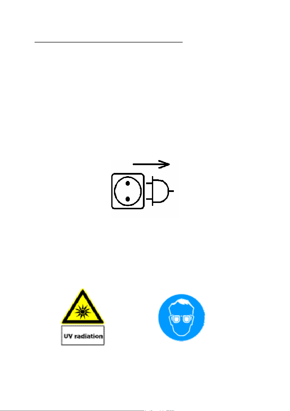
2.1.2 Important details on UV protection
It is very important to care for appropriate protection of skin and eyes when working with
transilluminators. Therefore, please use UV protection glasses or a UV full face protection
shield. Please use long-sleeved cloths as well as appropriate gloves!
Caution, Ultra-Violet Radiation! Protect your eyes!
Seite 7 von 29
Page 8

2.2 Maintenance
Periodic cleaning ensures constant, high-quality exposures. How often your transilluminator
has to be cleaned depends on various factors e.g. frequency of use and ambient conditions.
We recommend cleaning routinely at regular intervals.
Before cleaning unplug all components from the system voltage.
The cabinets of the single components can be cleaned with a damp cloth. If the cabinet is
very contaminated the cloth may also be damped with alcohol.
It is also recommended to clean carefully the cover as well as the filter glass plate with a
damp cloth. Please make sure that they are not cleaned with scouring or corrosive
detergents as they are damaging the filter glass as well as acetone, benzine and carbon
tetrachloride. Also avoid the use of isopropyl alcohol as it could cause stripes on the glass.
We recommend a cleaning with alcohol or glass cleaner.
All components of the system must not be dipped into water!
Important hint of use:
Do not deposit objects with sharp edges on the filter glass plate of the transilluminator. They
might damage the transilluminator and / or cause inhomogeneous exposures. Before
depositing an object on the filter glass plate make sure that it is free of not hardened, humid
paste and other aggressive substances that might get on the filter glass plate.
Seite 8 von 29
Page 9
3. System specifications
Basic system:
- operating voltage 100V~ up to 240V~, 50Hz/60Hz
- dimensions (L x D x H) 163 mm x 260 mm x 117 mm
- weight 3.2 kg
control ports for camera and b/w thermal printer P93E
-
- 5.7“ TFT- colour screen with 640 x 480 pixels
- keyboard with 8 keys
- USB port to save image data on USB stick
- exposure time control of camera from 0.04 sec up to 10.0 sec
- functions of image presentation:
• coloured display of over- and underexposure
• invert
- storage of 4 methodical presettings (Settings)
Camera and objective:
- greyscale camera for exposure of 10 seconds maximum
- resolution 752 x 582 pixels
-
manual zoom objective 8 – 48 mm
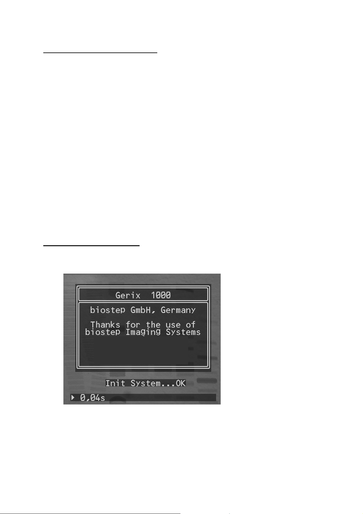
4. Insertion process
The system initialisation takes approx 5 sec. after switching on and ends with displaying
OK
.
Image 3 Display of successful system initialisation
Seite 9 von 29
Page 10

5. Display
The 8 keys of the keyboard can be divided in 4 groups:
- Control of camera
•
Live, Increase Exposure Time, Decrease Exposure Time, Auto, Capture
- Image processing
• Display of over- and underexposure, Invert
Export of the image exposed
-
• Save on USB, Print
- System settings
• Set
Image 4 System Display Gerix 1000
Seite 10 von 29
Page 11

Live-Image-Mode: Displays images with the shortest
exposure time (40 ms)
Exposure Mode: Raises the exposure time
Settings, Menu Navigation: Navigates in lists and input fields
Exposure Mode: Reduces the exposure time
Settings, Menu Navigation: Navigates in lists and input fields
Sat: Displays overexposed and under exposed areas in the image
Auto: Automatic settings of the optimum
exposure time
Invert: Inverts the image
Set: System Settings
Capture Mode: Stores momentarily the active image
Internal memory (“Freeze”)
Save to USB: Stores the active image on USB stick
Print: Prints the active image on the b/w
thermal printer Mitsubishi P93E
Seite 11 von 29
Page 12

6. Functions
6.1 Live-Image-Mode
When pressing this key the Live-Image-Mode is activated and the data stream with the
shortest exposure time (40 ms) is displayed.
The active image is immediately displayed regardless of the exposure time used at last
(Exposure Mode) or the activated capture mode (“frozen” image in internal memory).
If the function „Saturation“ is activated in Exposure / Capture Mode it will automatically be
Live
switched off with pressing the button
Mark for active Live-Image-Mode
Exposure time of Live-Image-Mode: 40 ms
.
Image 5 Active Live-Image-Mode
Seite 12 von 29
Page 13

6.2 Exposure Mode
With pressing the arrow keys the exposure time can be increased or decreased between the
range of 0.04 sec and 10.0 sec. If you press the key shortly the exposure time is changed by
0.04 sec. If you press the key permanently the time changes in 0.40 sec steps.
The arrow keys are used to navigate in the menu (Set).
Mark for Active Exposure Mode
Exposure time of Exposure Mode: e.g. 80 ms
Image 6 Active Exposure Mode
Seite 13 von 29
Page 14

6.3 Saturation / Mode Automatic Illumination
This key is used for 2 functions:
Sat
1. Function:
When pressing this button areas of the image that are over-, underexposed are displayed
coloured:
Areas overexposed are marked in red. Areas underexposed of inverted images are marked in
blue.
This applies for all images: images currently exposed (Live and Exposure Mode) and images
stored (Capture Mode).
If the LED next to the key
2. Function:
Besides the manual setting the exposure time can also be optimised automatically.
If you press the key
signalised with an “A” in the display and a blinking LED next to the key.
All pixels are analysed with the Gerix 1000 algorithm. It increases the exposure time
gradually until the first pixels (50 maximum) are overexposed. As soon as the optimal
exposure time is reached the automatic mode will be finished. You will notice this by an
acoustic signal. Now, the system will automatically switch to exposure mode.
(Saturation)
Sat / Auto
Auto
(Automatic Illumination)
Sat / Auto
Mark for Active Automatic Mode
Exposure time of Automatic Mode e.g. 5.12 s
is illuminated the function is activated.
for approx. 3 sec. the automatic mode is started. This is
Image 7 Active Mode Automatic Illumination
Seite 14 von 29
Page 15

Important Note:
The automatic mode can be finished with the following keys anytime:
- Arrow keys (Exposure Mode)
Æ a change in exposure time is stopped with the current value
- „Capture“
Æ the image is automatically stored in the latest state
- „Invert / Set“
Æ the image is automatically inverted in the latest state
Important Note:
If an image is overexposed it is not recommended to activate the automatic mode as the
algorithm is optimised for an increment of exposure time – not for a decrement.
Seite 15 von 29
Page 16

6.4 Invert / Set
This key is used for 2 functions:
1. Function:
When pressing this key the currently displayed image is displayed inverted.
It can be displayed originally by pressing again the key.
2. Function:
The system settings are subdivided into 4 ranges:
When pressing the key
Detailed information on the system settings can be found on pages 20 – 28.
Invert
Set
- Loading of methodic presettings (Load Settings)
- Storing of methodic presettings (Save Settings)
- Basic settings (System Settings)
- Information on the system (Information)
(System settings)
Invert / Set
for approx. 3 sec the menu is shown.
Mark for Active Inversion Mode
Image 8 Active Inversion Mode
Seite 16 von 29
Page 17

6.5 Capture Mode
With pressing this key the currently exposed image is frozen (saved) and the capture mode
is activated. If the image is saved in the internal memory no images are transferred from the
camera and displayed any more. Hence, the sample arranged under the camera can be
removed and the excitation wavelength (e.g. UV radiation of the transilluminator) be
switched off.
An image stored in the capture mode can be checked for over-/underexposure with the key
Sat / Auto
The mode can be exited with pressing again the key
. The image can also be inverted with the key
Capture
Mark for Active Capture Mode
Stored exposure time in the Capture Mode: e.g. 80 ms
Invert / Set
or the key
.
Live.
Image 9 Active Capture Mode
Seite 17 von 29
Page 18

6.6 Storage on USB stick
Plug the stick in the system. After connecting the stick with the control unit the USB stick is
checked for enough memory capacity.
When checking the LED next to the key
Save to USB
Information on active USB stick
USB stick during check
is blinking.
Image 10 Check for memory space of the USB stick connected
After the check is completed and enough memory space is available the quantity of images
to be stored on the stick is calculated and displayed in the upper right corner.
The LED next to the key is illuminated constantly as soon as the USB stick is approved.
Important Note:
We recommend to mainly use sticks with a memory capacity of 2 GB maximum. Although,
the system is tested for sticks with memory capacity up to 8 GB the use of sticks up to 2 GB
is advisable as results can be attained faster due to less expenditure of time used for the
checking of the memory capacity.
Seite 18 von 29
Page 19

To save the active image on the USB stick, press the key
The stick is automatically activated and the image saved by Gerix 1000.
The storage takes about 13 sec. A bar illustrates the process.
During the storage process the LED next to the key is blinking.
Display of images to be stored on the stick
yet
Information on the storage process
Save to USB
.
Image 11 Information during the storage process
The folder Gerix is uniquely created on the stick when starting the storage process.
Subfolders with the classification YY_MM_DD (Year_Month_Day) are created for each day
images are stored in. The file name of the image to be exported corresponds to the time
hh_mm_ss (Hour_Minute_Second) the transfer process has started. The images are saved
in TIF format (Greyscale TIF, 8 Bit) with a resolution of 688 x 571 pixels.
The quantity of images that can be saved yet on the stick is recalculated and displayed after
completing the storage.
Important Note:
When the message
Save to USB
to the stick could be caused!
USB active Do not remove!
is blinking do not plug the USB stick off the control unit. Data loss or damage
is displayed or the LED next to the key
Seite 19 von 29
Page 20

6.7 Print-out of image displayed
When pressing this key the image currently displayed is printed on the thermal printer
Mitsubishi P93E.
The image is printed corresponding to the information displayed i.e. all text information
shown are also printed.
Important Note:
You need to make sure that the Gerix system is correctly connected to the printer P93E with
the respective cord (3.5mm plug). If it is not connected or if you use another printer the
process has to be directly released at the printer itself.
The following printer settings are recommended for successful working:
It is based on the aspect that the image displayed is nearly identical to the print-out. In case
you would like to change the print-out the settings of brightness, contrast or Gamma can be
optimized until the quality requested is reached.
The settings for the size of print-out, quantity of print-outs, size of margin, positive and
negative prints can be adjusted to your requirements. Please read through the manual of the
printer Mitsubishi P93E.
Important Note:
In case, a different b/w thermal printer or video printer is used we cannot guarantee the
functionality of print process as well as the quality of the print-out.
Please inform about the connection specifications and settings of the respective printer in the
manual.
- Brightness (BRT): 0 [value range -19 … 0 … +19]
- Contrast (CONT): 0 [value range -19 … 0 … +19]
- Gamma (Γ): 5 [value range 1 … 5]
Seite 20 von 29
Page 21

7. System Settings
When pressing the key
It is structured into 4 ranges:
- Load Settings
- Save Settings
- System Settings
- Information (on the system)
The arrow keys help to navigate between the menu items being activated by pressing the
Invert / Set
key
Invert / Set
.
the menu of system settings is shown for 3 sec.
Image 12 Menu of System Settings
Seite 21 von 29
Page 22

7.1 Load Settings
One of four methodical presettings can be selected and used for the automated image
exposure for the work with the system Gerix 1000. Prerequisite is the storage of a
methodical presetting (menu item
Each of the 4 methodical presettings contains settings for:
- Exposure Time
- Function Over- and Underexposure - On/Off
- Function Invert – On/Off
The arrow keys help to navigate between the settings being activated by pressing the key
Invert / Set
.
Save Settings
).
Image 13 Menu Item Load Settings
Seite 22 von 29
Page 23

7.2 Save Settings
Up to 4 individual methodical presettings can be saved to facilitate the work of the users.
Four settings unassigned are available. They can be selected with the arrow keys. To save
the settings for exposure time, over- and underexposure and inverting currently used press
the key
Via the menu item
Invert / Set
.
Load Settings
all presettings stored can be activated and used for work.
Image 14 Menu Item Save Settings
Seite 23 von 29
Page 24

7.3 System Settings
The system settings are structured in 4 ranges:
- Date Format
- Set Time/Date
- Key tones (Peep) – On/Off
- Autosave – On/Off
These ranges can be selected with the arrow keys and activated by pressing the key
Invert / Set
.
Image 15 Menu Item System Settings
Seite 24 von 29
Page 25

7.4 Date Format
The date can be displayed in 4 different formats:
- DD.MM.YYYY (e.g. 30.09.2008)
- DD/MM/YYYY (e.g. 30/09/2008)
- MM/DD/YYYY (e.g. 09/30/2008)
- YYYY-MM-DD (e.g. 2008-09-30)
The formats can be selected with the arrow keys and activated by pressing the key
Invert / Set
.
Image 16 Date Format
Image 17 Date Format changed
Active Date Format
Seite 25 von 29
Page 26

7.5 Set Time/Date
Date and time can be set with this menu item.
Move the cursor (shape of rhombus) to the place that is to be set.
Cursor (Rhombus) to select the position
Image 18 Position to be changed
By pressing the key
Now, the value requested can be set with the arrow keys. When the correct value is set it
has be transferred by pressing the key
rhombus.
Invert / Set
the cursor changes to a triangle.
Invert / Set
Cursor (Triangle) to change the value
. The cursor changes again to a
Image 19 Change of position value
Seite 26 von 29
Page 27

Finally, the changed values need to be saved. For doing this move the cursor to the
Set
command
To exit the menu move the cursor to the command
and press the key
Invert / Set
.
Exit
and press the key
Invert / Set
.
Image 20 Transfer of changed values
Important Note:
In case changed values are not to be saved or the setting of date and time is to be cancelled
the menu can be exited anytime.
Seite 27 von 29
Page 28

7.6 Setting of key tone and Autosave
The key tone (
deactivated. For doing this select the requested command with the arrow keys. By pressing
the key
Invert / Set
The function
function is activated the following settings will automatically be saved when switching off:
The settings stored with
on.
After startup Gerix 1000 displays a live image to correctly place a sample on the
transilluminator and to set e.g. zoom and focus. The exposure time stored to expose the
image is activated with the arrow keys (
).
Mode
The function
Important Note:
The deactivation of the key tones has no influence on acoustic information of other system
functions (e.g. automatic setting of optimal exposure time).
Peep
) as well as the automatic storage of settings can be activated or
the function requested is switched on or off.
Autosave
supports fast process flows directly after system start. If this
- Exposure Time
- Over-, Underexposure – On/Off
- Invert – On/Off
Autosave
are directly activated when the system is again switch
Increasing of exposure time – Exposure
Peep
(de)activates a signal emission when pressing a key.
Image 21 Setting of key tone and automatic storage
Seite 28 von 29
Page 29

7.7 Information
This menu item displays the version of Gerix 1000 and USB firmware. The information can
be used required e.g. for service enquiries.
Image 22 Menu Item Information
8. Contact Details
We wish a pleasant working and excellent results with the system.
If you have any suggestions or hints resulting from the work, please do not hesitate to
contact us. We are always prepared to optimize the functions of the system Gerix1000.
Please contact:
Biotec-Fischer GmbH Tel.: +49-6408-6072
Daimlerstrasse 6 Fax: +49-6408-64165
35447 Reiskirchen e-mail: info@biotec-fischer.de
Seite 29 von 29
 Loading...