

Page 1

Instruction Manual
D102748X012
DLC3010 Digital Level Controller
Fisher™ FIELDVUE™ DLC3010 Digital Level
Controller
This manual applies to:
Device Type
Device Revision
Hardware Revision
Firmware Revision
DD Revision
Contents
Section 1 Introduction and Specifications 3.
Scope of Manual 3..............................
Conventions Used in this Manual 3................
Description 3..................................
Specifications 4................................
Related Documents 5...........................
Educational Services 5...........................
Section 2 Installation 15.................
Configuration: On the Bench or in the Loop 15......
Protecting the Coupling and Flexures 15...........
Mounting 17...................................
Hazardous Area Classifications and Special
Instructions for “Safe Use” and Installations
in Hazardous Locations 17....................
Mounting the 249 Sensor 17....................
Digital Level Controller Orientation 18............
Mounting the Digital Level Controller
on a 249 Sensor 20..........................
Mounting the Digital Level Controller for High
Temperature Applications 20.................
Electrical Connections 22........................
Power Supply 22..............................
Field Wiring 23................................
Grounding 24.................................
Shielded Wire 24..........................
Power/Current Loop Connections 25.............
RTD Connections 25...........................
Two‐Wire RTD Connections 25...............
Three‐Wire RTD Connections 25.............
Communication Connections 25.................
Test Connections 26...........................
Multichannel Installations 26....................
DLC3010
1
1
8
4
W7977-2
Alarm Jumper 27...............................
Changing Jumper Position 28....................
Loop Test 28...................................
Installation in Conjunction with a Rosemount
333 HART Tri‐Loopt HART‐to‐Analog
Signal Converter 29.............................
Multidrop Communication 99....................
Section 3 Overview 31...................
Section 4 Setup and Calibration 35........
Initial Setup 35.................................
Configuration Advice 36.........................
Preliminary Considerations 36....................
Write Protect 36..............................
Guided Setup 36...............................
Coupling 39..................................
Manual Setup 40...............................
Sensor 40....................................
Variables 42..................................
Ranging 43...................................
Process Conditions 44..........................
Device Identification 48........................
August 2020
www.Fisher.com
Page 2

DLC3010 Digital Level Controller
August 2020
Instruction Manual
D102748X012
Communications 48...........................
Polling Address 48.........................
Burst Mode 48............................
Burst Option 49...........................
Instrument Display 49..........................
Alert Setup 51.................................
Primary Variable 51............................
Temperature 56...............................
Calibration 58..................................
Primary 58...................................
Guided Calibration 58......................
Full Calibration 59.........................
Min/Max Calibration 59...................
Two Point Calibration 59..................
Weight Calibration 59....................
Theoretical Calibration 60...................
Partial Calibration 61.......................
Capture Zero 61.........................
Trim Gain 61............................
Trim Zero 61............................
Secondary 62.................................
Temperature Calibration 62.................
Trim Instrument Temperature 62..........
Trim Process Temperature 62..............
Analog Output CalibratIon 63................
Scaled D/A Trim 63......................
Calibration Examples 63........................
Calibration with Standard displacer and
Torque Tube 63.........................
Calibration with Overweight Displacer 65......
Density Applications - with Standard Displacer
and Torque Tube 66.....................
Calibration at Process Conditions (Hot Cut‐Over)
when input cannot be varied 67...........
Entering Theoretical Torque Tube Rates 68....
Excessive Mechanical Gain 68................
Determining the SG of an Unknown Fluid 69...
Accuracy Considerations 69.....................
Effect of Proportional Band 69...............
Density Variations in Interface Applications 69..
Extreme Temperatures 70...................
Temperature Compensation 70..............
Section 5 Service Tools 71...............
Active Alerts 71................................
Variables 73...................................
Maintenance 77................................
Section 6 Maintenance and
Troubleshooting 79....................
Diagnostic Messages 79.........................
Hardware Diagnostics 80........................
Test Terminals 82..............................
Removing the Digital Level
Controller from the Sensor 82....................
Removing the DLC3010 Digital Level Controller
from a 249 Sensor 83........................
Standard Temperature Applications 83........
High Temperature Applications 84...........
LCD Meter Assembly 84.........................
Removing the LCD Meter Assembly 85............
Replacing the LCD Meter Assembly 85............
Electronics Module 86...........................
Removing the Electronics Module 86.............
Replacing the Electronics Module 86.............
Terminal Box 87................................
Removing the Terminal Box 87..................
Replacing the Terminal Box 87...................
Removing and Replacing the Inner Guide
and Access Handle Assembly 88..................
Lever Assembly 89..............................
Removing the Lever Assembly 89................
Replacing the Lever Assembly 90................
Packing for Shipment 90.........................
Section 7 Parts 91......................
Parts Ordering 91...............................
Mounting Kits 91...............................
Repair Kits 91..................................
Parts List 92...................................
DLC3010 Digital Level Controllers 92.............
Transducer Assembly 93........................
Terminal Box Assembly 94......................
Terminal Box Cover Assembly 94.................
Mounting Parts 95.............................
249 Sensors with Heat Insulator 95...........
Appendix A Principle of Operation 99......
HART Communication 99........................
Digital Level Controller Operation 100.............
Appendix B Field Communicator
Menu Tree 105.......................
Glossary 112...........................
2
Page 3
DLC3010 Digital Level Controller
Instruction Manual
D102748X012
Introduction and Specifications
August 2020
Section 1 Introduction and Specifications
Scope of Manual1‐1‐
This instruction manual includes specifications, installation, operating, and maintenance information for FIELDVUE
DLC3010 digital level controllers.
™
This instruction manual supports the 475 Field Communicator or the AMS Trex
description revision 4, used with DLC3010 instruments with firmware revision 8. You can obtain information about the
process, instrument, or sensor using the Field Communicator. Contact your Emerson sales office
appropriate software.
Note
AMS Suite: Intelligent Device Manager can also be used to calibrate and configure the DLC3010, and to obtain information about
the process, instrument, or sensor.
Device Communicator with device
to obtain the
Do not install, operate, or maintain a DLC3010 digital level controller without being fully trained and
qualified in instrument, valve, actuator, and accessory installation, operation, and maintenance. To
avoid personal injury or property damage, it is important to carefully read, understand, and follow all
of the contents of this manual, including all safety cautions and warnings. If you have any questions
about these instructions, contact your Emerson sales office.
Conventions Used in this Manual
This manual describes using the Field Communicator to calibrate and configure the digital level controller.
Procedures that require the use of the Field Communicator have the text path and the sequence of numeric keys
required to display the desired Field Communicator menu.
For example, to access the Full Calibration menu:
Field Communicator Configure > Calibration > Primary > Full Calibration (2-4-1-2)
Menu selections are shown in italics, e.g., Calibrate. An overview of the Field Communicator menu structure is shown
in Appendix B.
Note
Fast-key sequences are only applicable to the 475 Field Communicator. They do not apply to the Trex Device Communicator.
Description
DLC3010 Digital Level Controllers
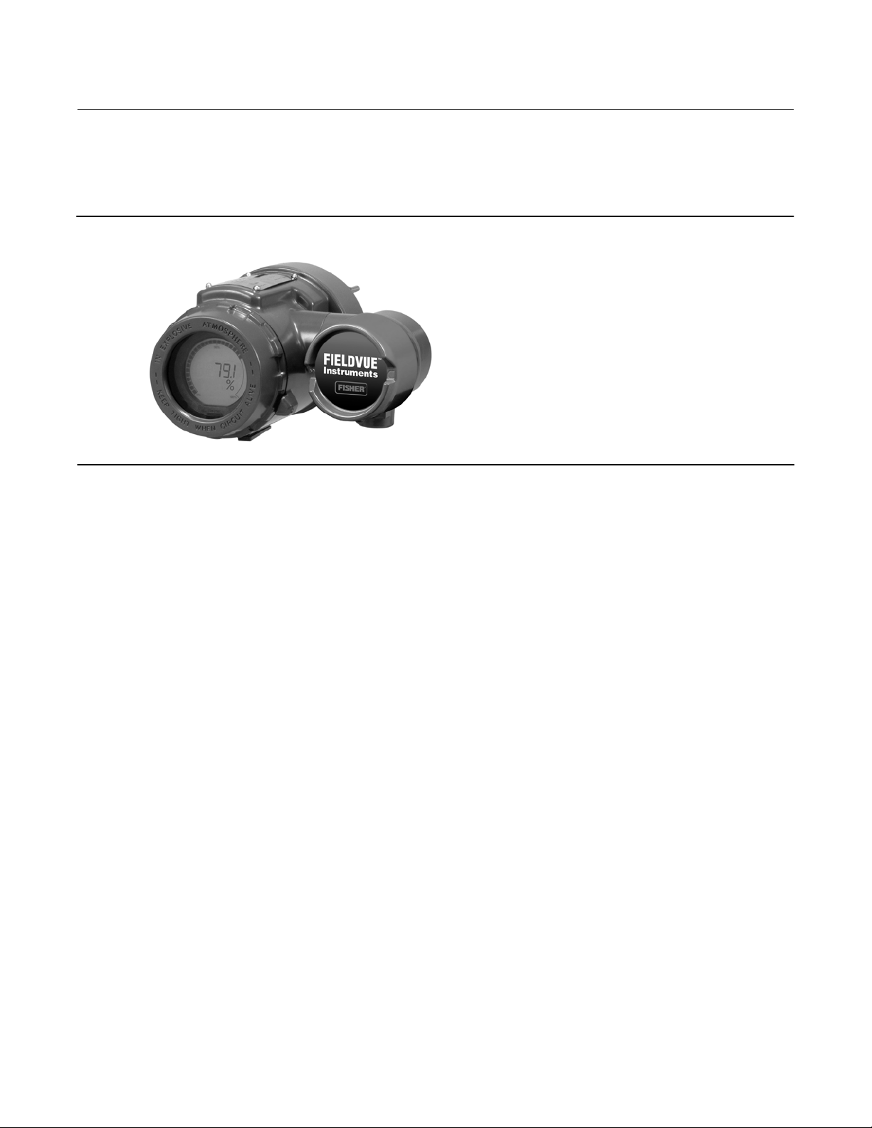
DLC3010 digital level controllers (figure 1‐1) are used with level sensors to measure liquid level, the level of interface
between two liquids, or liquid specific gravity (density). Changes in level or specific gravity exert a buoyant force on a
3
Page 4
DLC3010 Digital Level Controller
Introduction and Specifications
August 2020
displacer, which rotates the torque tube shaft. This rotary motion is applied to the digital level controller, transformed
to an electrical signal and digitized. The digital signal is compensated and processed per user configuration
requirements, and converted back to a 4‐20 mA analog electrical signal. The resulting current output signal is sent to
an indicating or final control element.
Figure 1‐1. FIELDVUE DLC3010 Digital Level Controller
W7977-2
Instruction Manual
D102748X012
DLC3010 digital level controllers are communicating, microprocessor‐based level, interface, or density sensing
instruments. In addition to the normal function of providing a 4‐20 milliampere current signal, DLC3010 digital level
controllers, using the HART
You can gain information from the process, the instrument, or the sensor using a Field Communicator with device
descriptions (DDs) compatible with DLC3010 digital level controllers. The Field Communicator may be connected at
the digital level controller or at a field junction box.
Using the Field Communicator, you can perform several operations with the DLC3010 digital level controller. You can
interrogate, configure, calibrate, or test the digital level controller. Using the HART protocol, information from the
field can be integrated into control systems or be received on a single loop basis.
DLC3010 digital level controllers are designed to directly replace standard pneumatic and electro‐pneumatic level
transmitters. DLC3010 digital level controllers mount on a wide variety of caged and cageless 249 level sensors. They
mount on other manufacturers' displacer type level sensors through the use of mounting adaptors.
R
communications protocol, give easy access to information critical to process operation.
249 Caged Sensors (see table 1‐6)
D 249, 249B, 249BF, 249C, 249K, and 249L sensors side‐mount on the vessel with the displacer mounted inside a cage
outside the vessel. (The 249BF caged sensor is available only in Europe, Middle East, and Africa.)
249 Cageless Sensors (see table 1‐7)
D 249BP, 249CP, and 249P sensors top‐mount on the vessel with the displacer hanging down into the vessel.
D 249VS sensor side‐mounts on the vessel with the displacer hanging out into the vessel.
D 249W wafer‐style sensor mounts on top of a vessel or on a customer‐supplied cage.
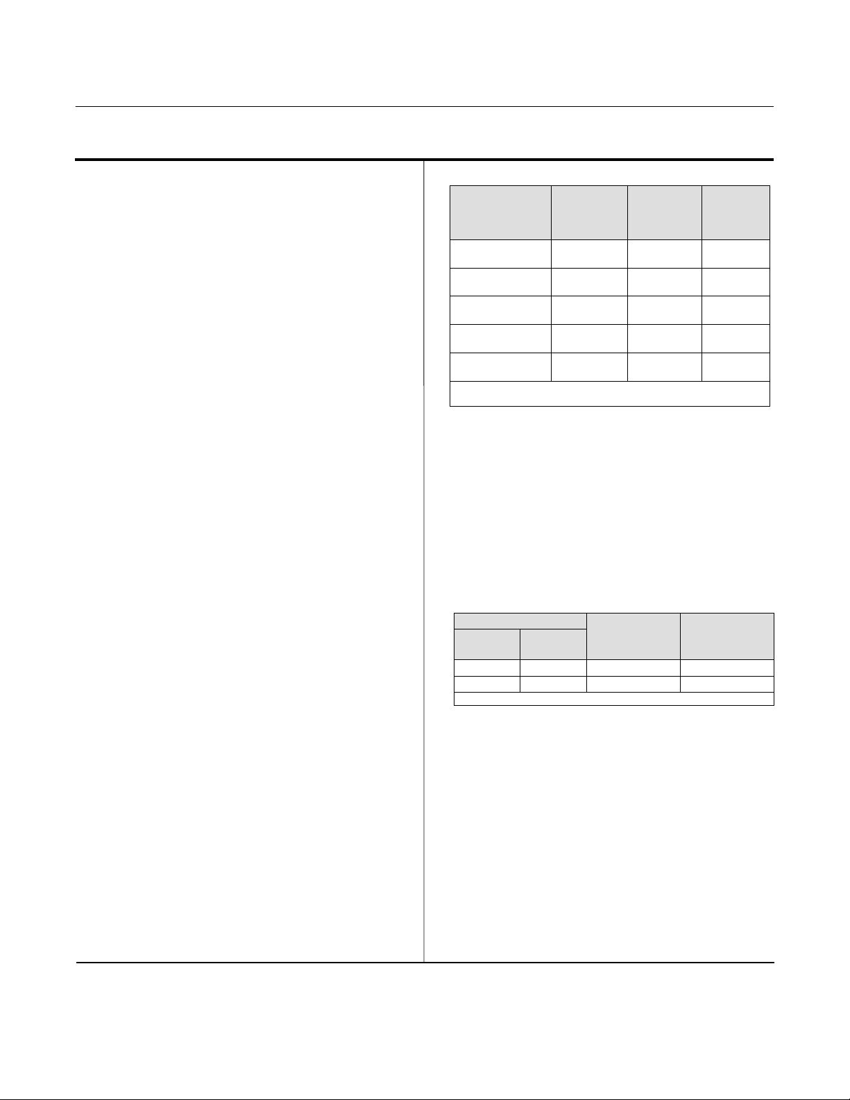
Specifications
Specifications for the DLC3010 digital level controller are shown in table 1‐1. Specifications for the 249 sensor are
shown in table 1‐3.
4
Page 5

DLC3010 Digital Level Controller
Instruction Manual
D102748X012
Introduction and Specifications
August 2020
Related Documents
Other documents containing information related to the DLC3010 digital level controller and 249 sensors include:
D Bulletin 11.2:DLC3010 - FIELDVUE DLC3010 Digital Level Controller (D102727X012
D FIELDVUE DLC3010 Digital Level Controller Quick Start Guide (D103214X012
D Using FIELDVUE Instruments with the Smart HART Loop Interface and Monitor (HIM) (D103263X012
D Audio Monitor for HART Communications (D103265X012
D Fisher 249 Caged Displacer Sensors Instruction Manual (D200099X012
D Fisher 249 Cageless Displacer Sensors Instruction Manual (D200100X012
D Fisher 249VS Cageless Displacer Sensor Instruction Manual (
D Fisher 249W Cageless Wafer Style Level Sensor Instruction Manual (D102803X012
D Simulation of Process Conditions for Calibration of Fisher Level Controllers and Transmitters (D103066X012
D Bolt Torque Information (D103220X012
D Technical Monograph 7: The Dynamics of Level and Pressure Control
D Technical Monograph 18: Level‐Trol Density Transmitter
D Technical Monograph 26: Guidelines for Selection of Liquid Level Control Equipment
)
)
)
)
D103288X012)
)
)
)
)
)
These documents are available from your Emerson sales office
or at Fisher.com.
Educational Services
For information on available courses for the DLC3010 digital level controller, as well as a variety of other products,
contact:
Emerson Automation Solutions
Educational Services, Registration
Phone: +1-641-754-3771 or +1-800-338-8158
e‐mail: education@emerson.com
emerson.com/fishervalvetraining
5
Page 6
DLC3010 Digital Level Controller
Introduction and Specifications
August 2020
Table 1‐1. DLC3010 Digital Level Controller Specifications
Instruction Manual
D102748X012
Available Configurations
DLC3010 Digital Level Controller:
Mounts on caged and cageless 249 sensors. See
tables 1‐6 and 1‐7 and sensor description.
Function: Transmitter
Communications Protocol: HART
Input Signal
Level, Interface, or Density: Rotary motion of torque
tube shaft proportional to changes in liquid level,
interface level, or density that change the buoyancy
of a displacer.
Process Temperature: Interface for 2‐ or 3‐wire 100
ohm platinum RTD for sensing process temperature,
or optional user‐entered target temperature to
permit compensating for changes in specific gravity
Output Signal
Analog: 4‐20 milliamperes DC (
Jdirect
action—increasing level, interface, or density
increases output; or
Jreverse action—increasing
level, interface, or density decreases output)
High saturation: 20.5 mA
Low saturation: 3.8 mA
High alarm: 22.5 mA
Low Alarm: 3.7 mA
Only one of the above high/low alarm definitions is
available in a given configuration. NAMUR NE 43
compliant when high alarm level is selected.
Digital: HART 1200 Baud FSK (frequency shift keyed)
HART impedance requirements must be met to
enable communication. Total shunt impedance
across the master device connections (excluding the
master and transmitter impedance) must be between
230 and 600 ohms. The transmitter HART receive
impedance is defined as:
Rx: 42K ohms and
Cx: 14 nF
Note that in point‐to‐point configuration, analog and
digital signalling are available. The instrument may be
queried digitally for information, or placed in Burst
mode to regularly transmit unsolicited process
information digitally. In multi‐drop mode, the output
current is fixed at 4 mA, and only digital
communication is available.
Performance
(1)
w/ NPS 3
249W, Using
a 14‐inch
Displacer
$0.8% of
output span
- - - - - -
$0.5% of
output span
- - - - - -
<1.0% of
output span
w/ All Other
249 Sensors
$0.5% of
output span
$0.3% of
output span
<1.0% of
output span
Performance
Criteria
Independent
Linearity
Hysteresis
Repeatability
Dead Band
Hysteresis plus
Deadband
NOTE: At full design span, reference conditions.
1. To lever assembly rotation inputs.
DLC3010
Digital Level
Controller
$0.25% of
output span
<0.2% of
output span
$0.1% of full
scale output
<0.05% of
input span
- - -
At effective proportional band (PB)<100%, linearity,
dead band, and repeatability are derated by the factor
(100%/PB)
Operating Influences
Power Supply Effect: Output changes <±0.2% of full
scale when supply varies between min. and max
voltage specifications.
Transient Voltage Protection: The loop terminals are
protected by a transient voltage suppressor. The
specifications are as follows:
Pulse Waveform
Rise Time
s)
10 1000 93.6 16
8 20 121 83
Note: μs = microsecond
Decay to
50% s)
Max V
CL
(Clamping
Voltage) (V)
Max I
PP
(Pulse Peak
@ Current) (A)
Ambient Temperature: The combined temperature
effect on zero and span without the 249 sensor is less
than 0.03% of full scale per degree Kelvin over the
operating range -40 to 80_C (-40 to 176_F)
Process Temperature: The torque rate is affected by
the process temperature (see figure 1‐2 and 1‐3). The
process density may also be affected by the process
temperature.
Process Density: The sensitivity to error in knowledge
of process density is proportional to the differential
density of the calibration. If the differential specific
gravity is 0.2, an error of 0.02 specific gravity units in
knowledge of a process fluid density represents 10%
of span.
-continued-
6
Page 7

Instruction Manual
D102748X012
Table 1‐1. DLC3010 Digital Level Controller Specifications (continued)
Electromagnetic Compatibility
Meets EN 61326‐1:2013 and EN 61326‐2‐3:2006
Immunity—Industrial locations per Table 2 of
EN 61326‐1 and Table AA.2 of EN 61326‐2‐3.
Performance is shown in table 1‐2 below.
Emissions—Class A
ISM equipment rating: Group 1, Class A
Supply Requirements (See figure 2‐10)
12 to 30 volts DC; 22.5 mA
Instrument has reverse polarity protection.
A minimum compliance voltage of 17.75 is required
to guarantee HART communication.
Compensation
Transducer compensation: for ambient temperature.
Density parameter compensation: for process
temperature (requires user‐supplied tables).
Manual compensation: for torque tube rate at target
process temperature is possible.
Digital Monitors
LCD Meter Indications
LCD meter indicates analog output on a percent scale
bar graph. The meter also can be configured to
display:
Process variable in engineering units only.
Percent range only.
Percent range alternating with process variable or
Process variable, alternating with process temperature
(and degrees of pilot shaft rotation).
Electrical Classification
Pollution Degree IV, Overvoltage Category II per IEC
61010 clause 5.4.2 d
Hazardous Area:
CSA— Intrinsically Safe, Explosion‐proof, Division 2,
Dust Ignition‐proof
FM— Intrinsically Safe, Explosion‐proof,
Non‐incendive, Dust Ignition‐proof
ATEX— Intrinsically Safe, Type n, Flameproof
IECEx— Intrinsically Safe, Type n, Flameproof
Electrical Housing:
CSA— Type 4X ATEX— IP66
FM— NEMA 4X IECEx— IP66
DLC3010 Digital Level Controller
Introduction and Specifications
August 2020
Linked to jumper‐selected Hi (factory default) or Lo
analog alarm signal:
Torque tube position transducer: Drive monitor and
signal reasonableness monitor
User‐configurable alarms: Hi‐Hi and Lo‐Lo Limit
process alarms
HART‐readable only:
RTD signal reasonableness monitor: When RTD
installed
Processor free‐time monitor.
Writes‐remaining in Non Volatile Memory monitor.
User‐configurable alarms: Hi and Lo limit process
alarms, Hi and Lo limit process temperature alarms,
and Hi and Lo limit electronics temperature alarms
Diagnostics
Output loop current diagnostic.
LCD meter diagnostic.
Spot specific gravity measurement in level mode: used
to update specific gravity parameter to improve
process measurement
Digital signal‐tracing capability: by review of
“troubleshooting variables”, and
Basic trending capability for PV, TV and SV.
Other Classifications/Certifications
CML— Certification Management Limited (Japan)
CUTR— Customs Union Technical Regulations (Russia,
Kazakhstan, Belarus, and Armenia)
ESMA— Emirates Authority for Standardization and
Metrology - ECAS-Ex (UAE)
INMETRO— National Institute of Metrology,
Standardization, and Industrial Quality (Brazil)
KTL— Korea Testing Laboratory (South Korea)
NEPSI— National Supervision and Inspection Centre
for Explosion Protection and Safety of
Instrumentation (China)
PESO CCOE— Petroleum and Explosives Safety
Organisation - Chief Controller of Explosives (India)
Contact your Emerson sales office
for
classification/certification specific information
Minimum Differential Specific Gravity
With a nominal 4.4 degrees torque tube shaft
rotation for a 0 to 100 percent change in liquid level
(specific gravity=1), the digital level controller can be
adjusted to provide full output for an input range of
5% of nominal input span. This equates to a minimum
differential specific gravity of 0.05 with standard
volume displacers.
-continued-
7
Page 8
DLC3010 Digital Level Controller
Introduction and Specifications
August 2020
Table 1‐1. DLC3010 Digital Level Controller Specifications (continued)
Instruction Manual
D102748X012
Minimum Differential Specific Gravity (continued)
See 249 sensor specifications for standard displacer
volumes and standard wall torque tubes. Standard
3
volume for 249C and 249CP sensors is ∼980 cm
3
in
), most others have standard volume of ∼1640 cm
(60
3
(100 in3).
Operating at 5% proportional band will degrade
accuracy by a factor of 20. Using a thin wall torque
tube, or doubling the displacer volume will each
roughly double the effective proportional band.
When proportional band of the system drops below
50%, changing displacer or torque tube should be
considered if high accuracy is a requirement.
Mounting Positions
Digital level controllers can be mounted right‐ or
left‐of‐displacer, as shown in figure 2‐5.
Instrument orientation is normally with the coupling
access door at the bottom, to provide proper
drainage of lever chamber and terminal
compartment, and to limit gravitational effect on the
lever assembly. If alternate drainage is provided by
user, and a small performance loss is acceptable, the
instrument could be mounted in 90 degree rotational
increments around the pilot shaft axis. The LCD meter
may be rotated in 90 degree increments to
accommodate this.
Construction Materials
Case and Cover: Low‐copper aluminum alloy
Internal: Plated steel, aluminum, and stainless steel;
encapsulated printed wiring boards; Neodymium Iron
Boron Magnets
NOTE: Specialized instrument terms are defined in ANSI/ISA Standard 51.1 - Process Instrument Terminology.
1. LCD meter may not be readable below -20_C (-4_F)
2. Contact your Emerson sales office
or application engineer if temperatures exceeding these limits are required.
Electrical Connections
Two 1/2‐14 NPT internal conduit connections; one on
bottom and one on back of terminal box. M20
adapters available.
Options
J Heat insulator J Mountings for Masoneilant,
Yamatake, and Foxborot‐Eckhardt displacers
available
J Level Signature Series Test (Performance
Validation Report) available (EMA only) for
instruments factory‐mounted on 249 sensor
J Factory Calibration: available for instruments
factory‐mounted on 249 sensor, when application,
process temperature and density(s) are supplied
J Device is compatible with user‐specified remote
indicator
Operating Limits
Process Temperature: See table 1‐4 and figure 2‐7.
Ambient Temperature and Humidity: See below
Conditions
Ambient
Temperature
Ambient
Relative
Humidity
Normal
(1,2)
Limits
-40 to 80_C
(-40 to 176_F)
0 to 95%,
(non‐condensing)
Transport and
Storage Limits
-40 to 85_C
(-40 to 185_F)
0 to 95%,
(non‐condensing)
Nominal
Reference
25_C
(77_F)
40%
Altitude Rating
Up to 2000 meters (6562 feet)
Weight
Less than 2.7 Kg (6 lb)
Table 1‐2. EMC Summary Results—Immunity
Port Phenomenon Basic Standard Test Level
Electrostatic discharge (ESD) IEC 61000‐4‐2
Enclosure
I/O signal/control
Note: RTD wiring must be shorter than 3 meters (9.8 feet)
1. A = No degradation during testing. B = Temporary degradation during testing, but is self‐recovering. Specification limit = +/- 1% of span.
2. HART communication was considered as “not relevant to the process” and is used primarily for configuration, calibration, and diagnostic purposes.
8
Radiated EM field IEC 61000‐4‐3
Rated power frequency
magnetic field
Burst IEC 61000‐4‐4
Surge IEC 61000‐4‐5
Conducted RF IEC 61000‐4‐6
IEC 61000‐4‐8
4 kV contact
8 kV air
80 to 1000 MHz @ 10V/m with 1 kHz AM at 80%
1400 to 2000 MHz @ 3V/m with 1 kHz AM at 80%
2000 to 2700 MHz @ 1V/m with 1 kHz AM at 80%
60 A/m at 50 Hz
1 kV
1 kV (line to ground only, each)
150 kHz to 80 MHz at 3 Vrms
Performance
(1)(2)
Criteria
A
A
A
A
B
A
Page 9
DLC3010 Digital Level Controller
Instruction Manual
D102748X012
Introduction and Specifications
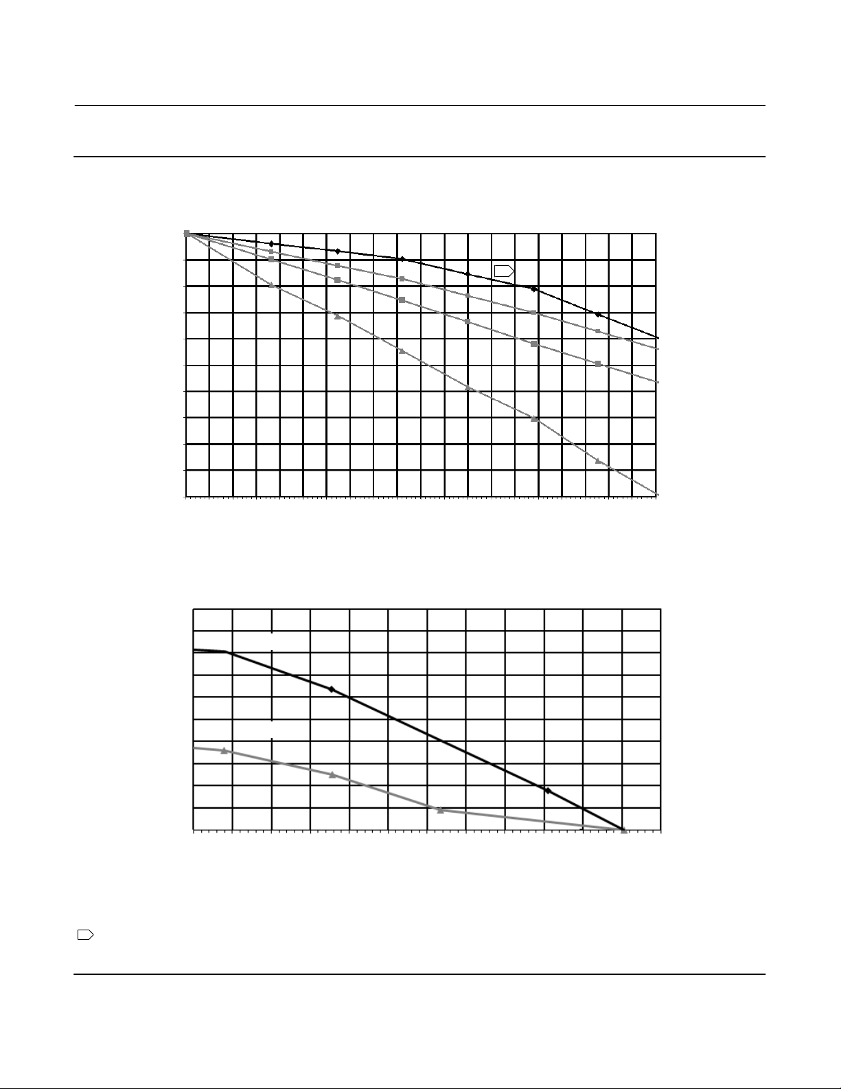
Figure 1‐2. Theoretical Reversible Temperature Effect on Common Torque Tube Materials, Degrees Celsius
TORQUE RATE REDUCTION
(NORMALIZED MODULUS OF RIGIDITY)
1.00
0.98
0.96
0.94
1
August 2020
norm
G
0.92
0.90
0.88
0.86
0.84
0.82
0.80
20 40 60 80 100 120 140 160 180 200 220 240 260 280 300 320 340 360 380 400 420
TEMPERATURE (_C)
TORQUE RATE AMPLIFICATION
(NORMALIZED MODULUS OF RIGIDITY)
1.10
norm
G
1.09
1.08
1.07
1.06
1.05
1.04
1.03
1.02
1.01
1.00
-200 -180 -160 -140 -120 -100 -80 -60 -40 -20 0 20 40
S31600
N05500
TEMPERATURE (_C)
CRYOGENIC
N05500
N06600
N10276
S31600
NOTES:
1 DUE TO THE PERMANENT DRIFT THAT OCCURS NEAR AND ABOVE 260_C, N05500 IS NOT
RECOMMENDED FOR TEMPERATURES ABOVE 232_C.
2 FOR PROCESS TEMPERATURES BELOW -29_C AND ABOVE 204_C SENSOR
MATERIALS MUST BE APPROPRIATE FOR THE PROCESS; SEE TABLE 1‐4.
9
Page 10
DLC3010 Digital Level Controller
Introduction and Specifications
August 2020
Instruction Manual
D102748X012
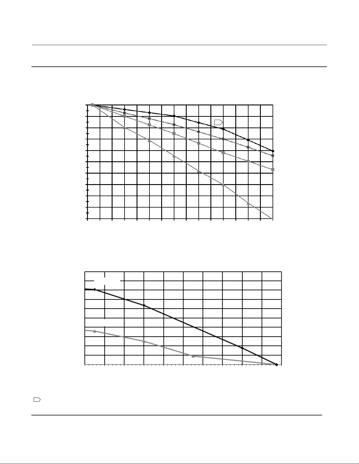
Figure 1‐3. Theoretical Reversible Temperature Effect on Common Torque Tube Materials, Degrees Fahrenheit
TORQUE RATE REDUCTION
(NORMALIZED MODULUS OF RIGIDITY)
1.00
0.98
0.96
0.94
1
0.92
norm
0.90
G
0.88
0.86
0.84
0.82
0.80
50 100 150 200 250 300 350 400 450 500 550 600 650 700 750 800
TEMPERATURE (_F)
TORQUE RATE AMPLIFICATION
(NORMALIZED MODULUS OF RIGIDITY)
1.10
1.09
1.08
1.07
1.06
1.05
norm
G
1.04
1.03
1.02
1.01
1.00
NOTE:
1 DUE TO THE PERMANENT DRIFT THAT OCCURS NEAR AND ABOVE 500_F, N05500 IS NOT
RECOMMENDED FOR TEMPERATURES ABOVE 450_F.
2 FOR PROCESS TEMPERATURES BELOW -20_F AND ABOVE 400_F SENSOR
MATERIALS MUST BE APPROPRIATE FOR THE PROCESS; SEE TABLE 1‐4.
S31600
N05500
-320 -280 -240 -200 -160 -120 -80 -40 0 40 80
TEMPERATURE (_F)
CRYOGENIC
N05500
N06600
N10276
S31600
10
Page 11
Instruction Manual
(1)
D102748X012
Table 1‐3. 249 Sensor Specifications
Input Signal
Liquid Level or Liquid‐to‐Liquid Interface Level:
From 0 to 100 percent of displacer length
Liquid Density: From 0 to 100 percent of
displacement force change obtained with given
displacer volume—standard volumes are
(60 inches3) for 249C and 249CP sensors or J1640
3
cm
(100 inches3) for most other sensors; other
volumes available depending upon sensor
construction
Sensor Displacer Lengths
See tables 1‐6 and 1‐7 footnotes
Sensor Working Pressures
Consistent with applicable ANSI
pressure/temperature ratings for the specific sensor
constructions shown in tables 1‐6 and 1‐7
Caged Sensor Connection Styles
Cages can be furnished in a variety of end connection
styles to facilitate mounting on vessels; the
J980 cm
DLC3010 Digital Level Controller
Introduction and Specifications
August 2020
equalizing connection styles are numbered and are
shown in figure 1‐4.
Mounting Positions
Most level sensors with cage displacers have a
3
rotatable head. The head may be rotated through
360 degrees to any of eight different positions, as
shown in figure 2‐5.
Construction Materials
See tables 1‐5, 1‐6, and 1‐7
Operative Ambient Temperature
See table 1‐4
For ambient temperature ranges, guidelines, and use
of optional heat insulator, see figure 2‐7.
Options
J Heat insulator J Gauge glass for pressures to 29
bar at 232_C (420 psig at 450_F), and
J Reflex
gauges for high temperature and pressure
applications
Table 1‐4. Allowable Process Temperatures for
Common 249 Sensor Pressure Boundary Materials
MATERIAL
Cast Iron -29_C (-20_F) 232_C (450_F)
Steel -29_C (-20_F) 427_C (800_F)
Stainless Steel -198_C (-325_F) 427_C (800_F)
N04400 -198_C (-325_F) 427_C (800_F)
Graphite
Laminate/SST
Gaskets
N04400/PTFE
Gaskets
-198_C (-325_F) 427_C (800_F)
-73_C (-100_F) 204_C (400_F)
PROCESS TEMPERATURE
Min. Max.
Table 1‐5. Displacer and Torque Tube Materials
Part Standard Material Other Materials
316 Stainless Steel,
Displacer 304 Stainless Steel
Displacer Stem
Driver Bearing,
Displacer Rod
and Driver
Torque Tube N05500
1. N05500 is not recommended for spring applications above 232_C
(450_F). Contact your Emerson sales office
temperatures exceeding this limit are required.
316 Stainless Steel
N10276, N04400,
Plastic, and Special
Alloys
N10276, N04400,
other Austenitic
Stainless Steels, and
Special Alloys
316 Stainless Steel,
N06600, N10276
or application engineer if
11
Page 12
DLC3010 Digital Level Controller
(1)
(5)
(1)
(2)
(3)
Introduction and Specifications
August 2020
Instruction Manual
Table 1‐6. Caged Displacer Sensors
TORQUE TUBE
ORIENTATION
249
SENSOR
(3)
STANDARD CAGE, HEAD,
AND TORQUE TUBE ARM
MATERIAL
Cast iron
Screwed 1‐1/2 or 2
Flanged 2
Screwed or optional socket weld 1‐1/2 or 2 CL600
249B, 249BF
Torque tube
(4)
Steel
Raised face or optional ring‐type joint
flanged
arm rotatable
with respect to
Screwed 1‐1/2 or 2 CL600
equalizing
connections
(3)
249C
316 stainless steel
249K Steel
Raised face flanged
Raised face or optional ring‐type joint
flanged
249L Steel Ring‐type joint flanged 2
1. Standard displacer lengths for all styles (except 249) are 14, 32, 48, 60, 72, 84, 96, 108 and 120 inches. The 249 uses a displacer with a length of either 14 or 32 inches.
2. EN flange connections available in EMA (Europe, Middle East and Africa).
3. Not available in EMA.
4. The 249BF available in EMA only. Also available in EN size DN 40 with PN 10 to PN 100 flanges and size DN 50 with PN 10 to PN 63 flanges.
5. Top connection is NPS 1 ring‐type joint flanged for connection styles F1 and F2.
EQUALIZING CONNECTION
Style Size (NPS)
1‐1/2
2
1‐1/2
2
1‐1/2 or 2 CL900 or CL1500
D102748X012
PRESSURE RATING
CL125 or CL250
CL150, CL300, or
CL600
CL150, CL300, or
CL600
CL150, CL300, or
CL600
CL150, CL300, or
CL600
CL2500
(2)
Table 1‐7. Cageless Displacer Sensors
Standard Head
Mounting Sensor
Body
(6)
and Torque Tube
Arm Material
(4)
Mounts on
249BP
249CP 316 Stainless Steel NPS 3 raised face CL150, CL300, or CL600
Steel
top of vessel
(5)
Mounts on
side of vessel
249P
249VS
Steel or stainless steel
WCC (steel) LCC (steel), or
CF8M (316 stainless steel)
WCC, LCC, or CF8M For NPS 4 buttweld end, XXZ CL2500
Mounts on top of
vessel or on
customer
249W
supplied cage
1. Standard displacer lengths are 14, 32, 48, 60, 72, 84, 96, 108, and 120 inches.
2. Not used with side‐mounted sensors.
3. EN flange connections available in EMA (Europe, Middle East and Africa).
4. Not available in EMA.
5. 249P available in EMA only.
6. Wafer Body only applicable to the 249W.
WCC or CF8M For NPS 3 raised face CL150, CL300, or CL600
LCC or CF8M For NPS 4 raised face CL150, CL300, or CL600
,
Wafer
Flange Connection (Size) Pressure Rating
NPS 4 raised face or optional ring‐type joint CL150, CL300, or CL600
NPS 6 or 8 raised face CL150 or CL300
NPS 4 raised face or optional ring‐type joint
NPS 6 or 8 raised face
CL900 or 1CL500
(EN PN 10 to DIN PN 250)
CL150, CL300, CL600, CL900,
CL1500, or CL2500
CL125, CL150, CL250, CL300,
For NPS 4 raised face or flat face
CL600, CL900, or CL1500
(EN PN 10 to DIN PN 160)
12
Page 13
Instruction Manual
D102748X012
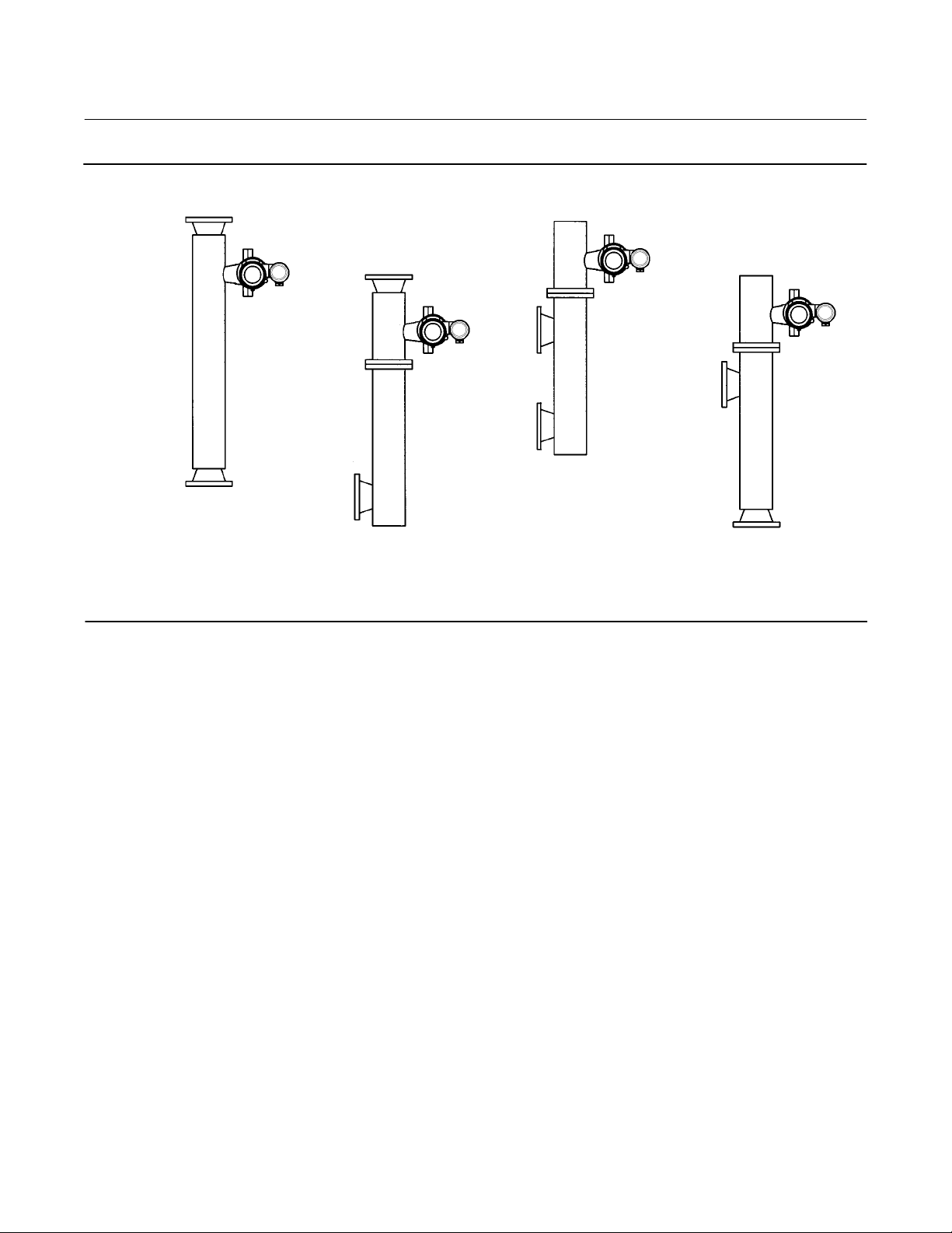
Figure 1‐4. Style Number of Equalizing Connections
DLC3010 Digital Level Controller
Introduction and Specifications
August 2020
TOP AND BOTTOM CONNECTIONS,
STYLE 1
SCREWED (S-1) OR FLANGED (F-1)
UPPER AND LOWER SIDE CONNECTIONS,
STYLE 2
TOP AND LOWER SIDE CONNECTIONS,
SCREWED (S-2) OR FLANGED (F-2)
STYLE 3
SCREWED (S-3) OR FLANGED (F-3)
STYLE 4
UPPER SIDE AND BOTTOM CONNECTIONS,
SCREWED (S-4) OR FLANGED (F-4)
13
Page 14

DLC3010 Digital Level Controller
Introduction and Specifications
August 2020
Instruction Manual
D102748X012
14
Page 15

DLC3010 Digital Level Controller
Instruction Manual
D102748X012
Installation
August 2020
Section 2 Installation2-2-
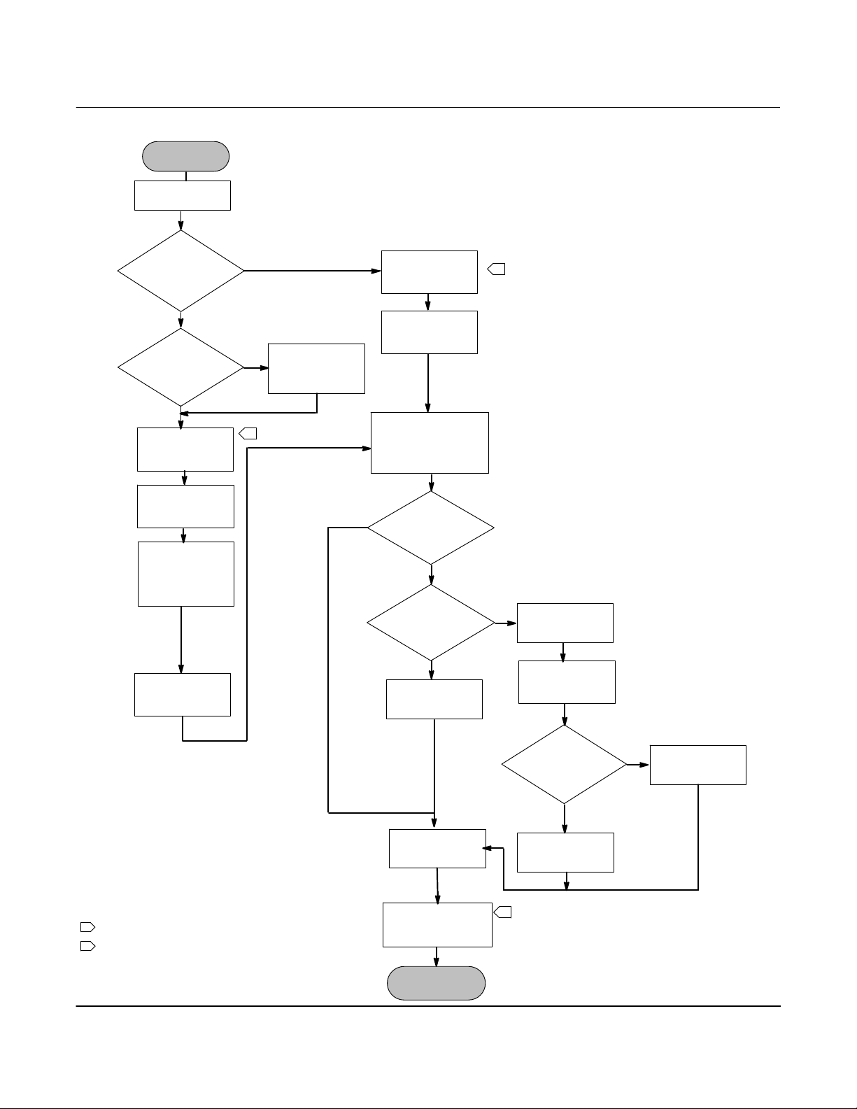
This section contains digital level controller installation information including an installation flowchart (figure 2‐1),
mounting and electrical installation information, and a discussion of failure mode jumpers.
Configuration: On the Bench or in the Loop
Configure the digital level controller before or after installation. It may be useful to configure the instrument on the
bench before installation to ensure proper operation, and to familiarize yourself with its functionality.
Protecting the Coupling and Flexures
CAUTION
Damage to flexures and other parts can cause measurement errors. Observe the following steps before moving the sensor
and controller.
Lever Lock
The lever lock is built in to the coupling access handle. When the handle is open, it positions the lever in the neutral
travel position for coupling. In some cases, this function is used to protect the lever assembly from violent motion
during shipment.
A DLC3010 controller will have one of the following mechanical configurations when received:
1. A fully assembled and coupled caged‐displacer system shipped with the displacer or driver rod blocked within the
operating range by mechanical means. In this case, the access handle (figure 2‐4) will be in the unlocked position.
Remove the displacer‐blocking hardware before calibration. (See the appropriate sensor instruction manual). The
coupling should be intact.
CAUTION
When shipping an instrument mounted on a sensor, if the lever assembly is coupled to the linkage, and the linkage is
constrained by the displacer blocks, use of the lever lock may result in damage to bellows joints or flexure.
2. If the displacer cannot be blocked because of cage configuration or other concerns, the transmitter is uncoupled
from the torque tube by loosening the coupling nut, and the access handle will be in the locked position. Before
placing such a configuration into service, perform the Coupling procedure found on page 39.
3. For a cageless system where the displacer is not connected to the torque tube during shipping, the torque tube
itself stabilizes the coupled lever position by resting against a physical stop in the sensor. The access handle will be
in the unlocked position. Mount the sensor and hang the displacer. The coupling should be intact.
15
Page 16
DLC3010 Digital Level Controller
Installation
August 2020
Figure 2‐1. Installation Flowchart
START HERE
Check Alarm
Jumper Position
Instruction Manual
D102748X012
Factory mounted
on 249 sensor?
No
High
temperature
application?
No
Mount and Wire
Digital level
Controller
Power
Digital level
Controller
Use Instrument
Setup to enter
sensor data and
calibration
condition
Yes
Yes
1
Install heat
insulator
assembly
Digital Level
Controller
Digital Level
Controller
Enter Tag, Messages,
Date, and check or set
target application data
Yes
Measurement?
Temperature
Correction?
Wire
Power
Density
Using
No
1
Yes
Set
Temperature
Units
Calibrate
sensor
NOTE:
1 IF USING RTD FOR TEMPERATURE CORRECTION,
ALSO WIRE RTD TO DIGITAL LEVEL CONTROLLER
2 WRITE PROTECT IS EFFECTIVE ONLY IF THE DLC3010 REMAINS
POWERED‐UP
16
No
Set
Specific Gravity
Set
Range Values
Set Write Protect
DONE
2
Setup specific
gravity tables
Using RTD?
No
Enter Process
Temperature
Yes
Setup and
Calibrate RTD
Page 17

DLC3010 Digital Level Controller
Instruction Manual
D102748X012
4. If the controller was shipped alone, the access handle will be in the locked position. All Mounting, Coupling and
Calibration procedures must be performed.
The access handle includes a retaining set screw, as shown in figures 2‐4 and 2‐6. The screw is driven in to contact the
spring plate in the handle assembly before shipping. It secures the handle in the desired position during shipping and
operation. To set the access handle in the open or closed position, this set screw must be backed out so that its top is
flush with the handle surface.
Installation
August 2020
Mounting
WARNING
To avoid personal injury, always wear protective gloves, clothing, and eyewear when performing any installation
operations.
Personal injury or property damage due to sudden release of pressure, contact with hazardous fluid, fire, or explosion can
be caused by puncturing, heating, or repairing a displacer that is retaining process pressure or fluid. This danger may not
be readily apparent when disassembling the sensor or removing the displacer. Before disassembling the sensor or
removing the displacer, observe the appropriate warnings provided in the sensor instruction manual.
Check with your process or safety engineer for any additional measures that must be taken to protect against process
media.
Hazardous Area Classifications and Special Instructions for “Safe Use” and
Installations in Hazardous Locations
Refer to the DLC3010 Quick Start Guide (D103214X012) that ships with the instrument for Hazardous Area
Classifications and Special Instructions for “Safe Use” and Installations in Hazardous Locations. If a copy of this quick
start guide is needed contact your Emerson sales office
or go to Fisher.com.
Mounting the 249 Sensor
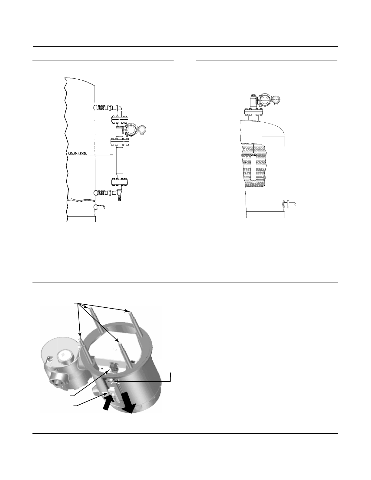
The 249 sensor is mounted using one of two methods, depending on the specific type of sensor. If the sensor has a
caged displacer, it typically mounts on the side of the vessel as shown in figure 2‐2. If the sensor has a cageless
displacer, the sensor mounts on the side or top of the vessel as shown in figure 2‐3.
The DLC3010 digital level controller is typically shipped attached to the sensor. If ordered separately, it may be
convenient to mount the digital level controller to the sensor and perform the initial setup and calibration before
installing the sensor on the vessel.
Note
Caged sensors have a rod and block installed on each end of the displacer to protect the displacer in shipping. Remove these parts
before installing the sensor to allow the displacer to function properly.
17
Page 18
DLC3010 Digital Level Controller
Installation
August 2020
Instruction Manual
D102748X012
Figure 2‐2. Typical Caged Sensor Mounting Figure 2‐3. Typical Cageless Sensor Mounting
Digital Level Controller Orientation
Mount the digital level controller with the torque tube shaft clamp access hole (see figure 2‐4) pointing downward to
allow accumulated moisture drainage.
Figure 2‐4. Sensor Connection Compartment (Adapter Ring Removed for Clarity)
MOUNTING
STUDS
ACCESS
HOLE
SHAFT CLAMP
SET SCREW
PRESS HERE TO
MOVE ACCESS
HANDLE
SLIDE ACCESS HANDLE
TOWARD FRONT OF UNIT
TO EXPOSE ACCESS HOLE
18
Page 19

DLC3010 Digital Level Controller
Instruction Manual
D102748X012
Note
If alternate drainage is provided by the user, and a small performance loss is acceptable, the instrument could be mounted in 90
degree rotational increments around the pilot shaft axis. The LCD meter may be rotated in 90 degree increments to accommodate
this.
Installation
August 2020
The digital level controller and torque tube arm are attached to the sensor either to the left or right of the displacer, as
shown in figure 2‐5. This can be changed in the field on the 249 sensors (refer to the appropriate sensor instruction
manual). Changing the mounting also changes the effective action, because the torque tube rotation for increasing
level, (looking at the protruding shaft), is clockwise when the unit is mounted to the right of the displacer and counter‐
clockwise when the unit is mounted to the left of the displacer.
All caged 249 sensors have a rotatable head. That is, the digital level controller can be positioned at any of eight
alternate positions around the cage as indicated by the position numbers 1 through 8 in figure 2‐5. To rotate the head,
remove the head flange bolts and nuts and position the head as desired.
Figure 2‐5. Typical Mounting Positions for the FIELDVUE DLC3010 Digital Level Controller on Fisher 249 Sensor
SENSOR
CAGED
CAGELESS
LEFT-OF-DISPLACER
7
1
5
1
3
6
4
8
2
3
1
7
RIGHT-OF-DISPLACER
5
1
2
8
4
6
1 Not available for 249C and 249K.
19
Page 20
DLC3010 Digital Level Controller
Installation
August 2020
Instruction Manual
D102748X012
Mounting the Digital Level Controller on a 249 Sensor
Refer to figure 2‐4 unless otherwise indicated.
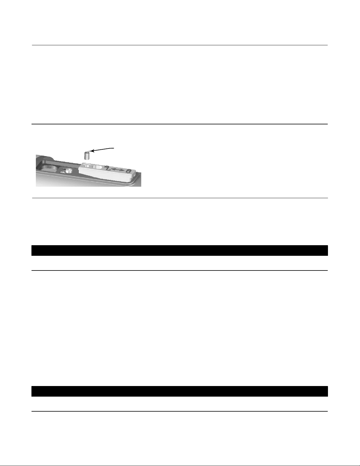
1. If the set‐screw in the access handle (figure 2‐6) is driven against the spring plate, back it out until the head is flush
with the outer surface of the handle, using a 2 mm hex key. Slide the access handle to the locked position to expose
the access hole. Press on the back of the handle as shown in figure 2‐4 then slide the handle toward the front of the
unit. Be sure the locking handle drops into the detent.
Figure 2‐6. Close‐up of Set‐Screw
SET‐SCREW
2. Using a 10 mm deep well socket inserted through the access hole, loosen the shaft clamp (figure 2‐4). This clamp
will be re‐tightened in the Coupling portion of the Initial Setup section.
3. Remove the hex nuts from the mounting studs. Do not remove the adapter ring.
CAUTION
Measurement errors can occur if the torque tube assembly is bent or misaligned during installation.
4. Position the digital level controller so the access hole is on the bottom of the instrument.
5. Carefully slide the mounting studs into the sensor mounting holes until the digital level controller is snug against
the sensor.
6. Reinstall the hex nuts on the mounting studs and tighten the hex nuts to 10 NSm (88.5 lbfSin).
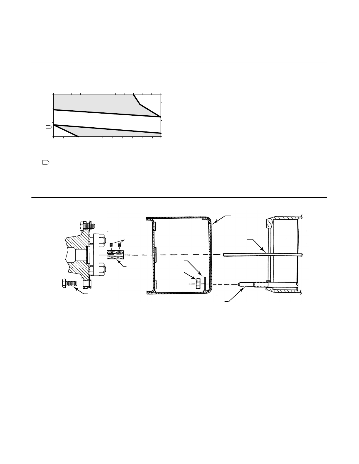
Mounting the Digital Level Controller for High Temperature Applications
Refer to figure 2‐8 for parts identification except where otherwise indicated.
The digital level controller requires an insulator assembly when temperatures exceed the limits shown in figure 2‐7.
A torque tube shaft extension is required for a 249 sensor when using an insulator assembly.
CAUTION
Measurement errors can occur if the torque tube assembly is bent or misaligned during installation.
20
Page 21
Instruction Manual
D102748X012
Figure 2‐7. Guidelines for Use of Optional Heat Insulator Assembly
DLC3010 Digital Level Controller
Installation
August 2020
-40 -30
800
-20 -10
010 20
30 40 50 60
AMBIENT TEMPERATURE (_C)
HEAT INSULATOR
400
0
1
TOO
COLD
-325
PROCESS TEMPERATURE (_F)
NO HEAT INSULATOR NECESSARY
0 20 40 60 80 100 120 140 160
-20-40
REQUIRED
HEAT INSULATOR
REQUIRED
AMBIENT TEMPERATURE (_F)
70
TOO
HOT
80
176
425
400
300
200
100
0
-100
-200
PROCESS TEMPERATURE (_C)
STANDARD TRANSMITTER
NOTES:
1 FOR PROCESS TEMPERATURES BELOW -29_C (-20_F) AND ABOVE 204_C (400_F)
SENSOR MATERIALS MUST BE APPROPRIATE FOR THE PROCESS; SEE TABLE 1‐4.
2. IF AMBIENT DEW POINT IS ABOVE PROCESS TEMPERATURE, ICE FORMATION MIGHT
CAUSE INSTRUMENT MALFUNCTION AND REDUCE INSULATOR EFFECTIVENESS.
39A4070‐B
A5494‐1
Figure 2‐8. Digital Level Controller Mounting on Sensor in High Temperature Applications
INSULATOR
(KEY 57)
SET SCREWS
(KEY 60)
SHAFT
EXTENSION
(KEY 58)
WASHER
SHAFT
COUPLING
(KEY 59)
(KEY 78)
HEX NUTS
(KEY 34)
CAP SCREWS
MN28800
20A7423‐C
B2707
(KEY 63)
SENSOR
MOUNTING STUDS
(KEY 33)
DIGITAL LEVEL CONTROLLER
1. For mounting a digital level controller on a 249 sensor, secure the shaft extension to the sensor torque tube shaft
via the shaft coupling and set screws, with the coupling centered as shown in figure 2‐8.
2. Slide the access handle to the locked position to expose the access hole. Press on the back of the handle as shown in
figure 2‐4 then slide the handle toward the front of the unit. Be sure the locking handle drops into the detent.
3. Remove the hex nuts from the mounting studs.
4. Position the insulator on the digital level controller, sliding the insulator straight over the mounting studs.
5. Install 4 washers (key 78) over the studs. Install the four hex nuts and tighten.
6. Carefully slide the digital level controller with the attached insulator over the shaft coupling so that the access hole
is on the bottom of the digital level controller.
7. Secure the digital level controller and insulator to the torque tube arm with four cap screws.
8. Tighten the cap screws to 10 NSm (88.5 lbfSin).
21
Page 22
DLC3010 Digital Level Controller
Installation
August 2020
Instruction Manual
D102748X012
Electrical Connections
WARNING
Select wiring and/or cable glands that are rated for the environment of use (such as hazardous area, ingress protection and
temperature). Failure to use properly rated wiring and/or cable glands can result in personal injury or property damage
from fire or explosion.
Wiring connections must be in accordance with local, regional, and national codes for any given hazardous area approval.
Failure to follow the local, regional, and national codes could result in personal injury or property damage from fire or
explosion.
Proper electrical installation is necessary to prevent errors due to electrical noise. A resistance between 230 and 600
ohms must be present in the loop for communication with a Field Communicator. Refer to figure 2‐9 for current loop
connections.
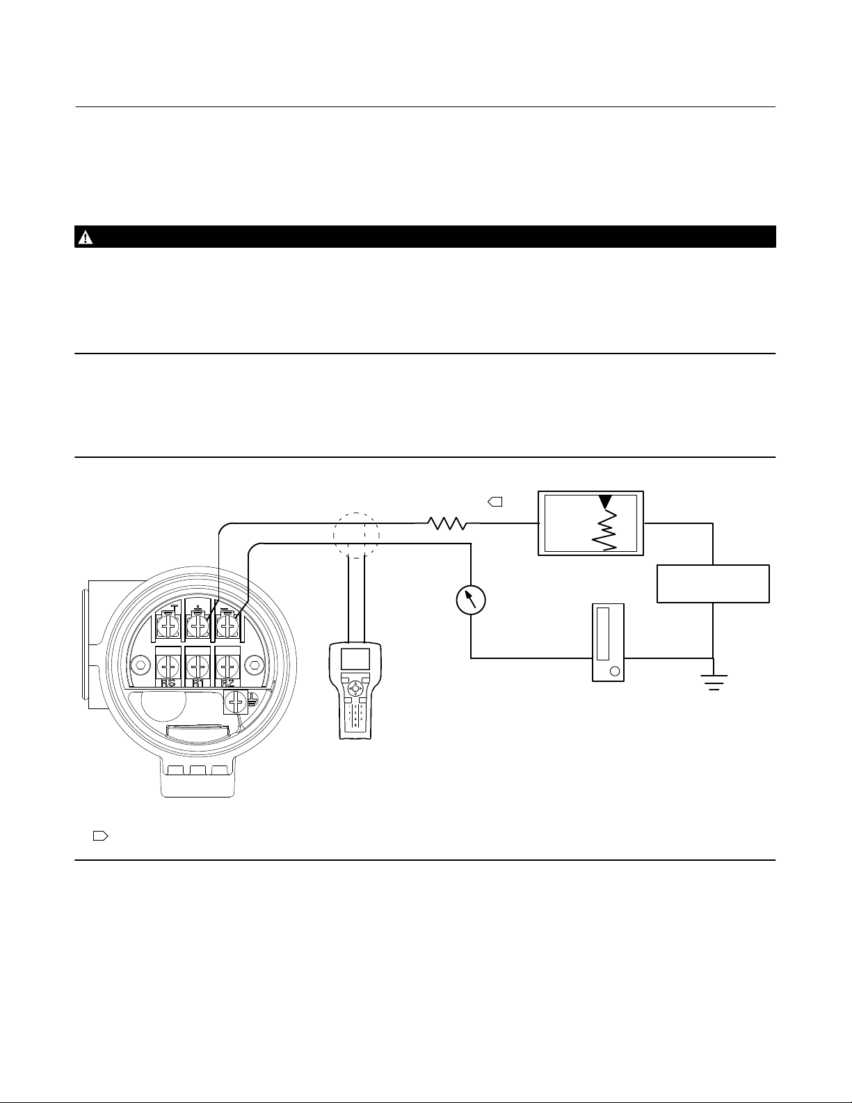
Figure 2‐9. Connecting a Field Communicator to the Digital Level Controller Loop
NOTE:
1 THIS REPRESENTS THE TOTAL SERIES LOOP RESISTANCE.
E0363
230 RL 600
A Field Communicator may be
connected at any termination
point in the signal loop other
than across the power supply.
Signal loop must have between
230 and 600 ohms load for
communication.
1
−
Reference meter
for calibration
+
or monitoring
operation. May
be a voltmeter
across 250 ohm
−
resistor or a
current meter.
+
+
Signal loop may be grounded at
any point or left ungrounded.
−
+
POWER
SUPPLY
−
Power Supply
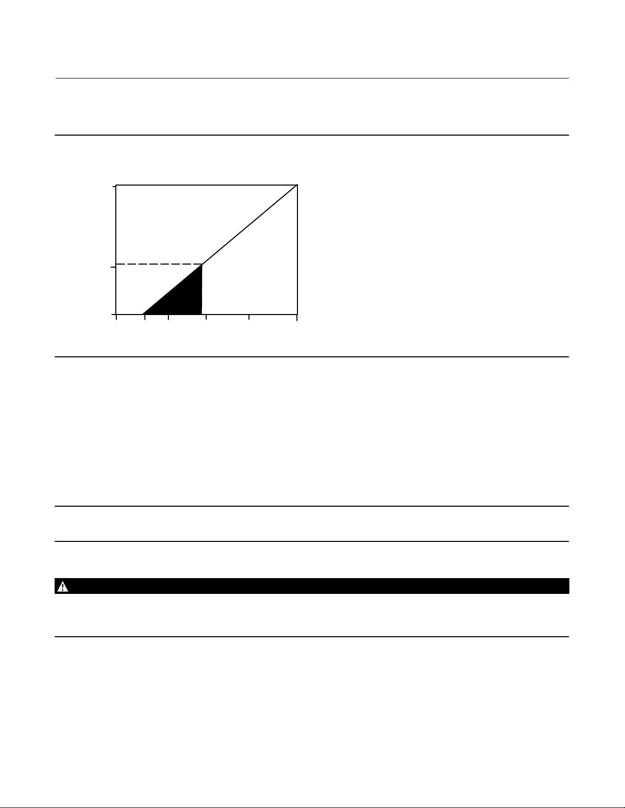
To communicate with the digital level controller, you need a 17.75 volt DC minimum power supply. The power
supplied to the transmitter terminals is determined by the available supply voltage minus the product of the total loop
resistance and the loop current. The available supply voltage should not drop below the lift‐off voltage. (The lift‐off
voltage is the minimum “available supply voltage” required for a given total loop resistance). Refer to figure 2‐10 to
22
Page 23
DLC3010 Digital Level Controller
Instruction Manual
D102748X012
Installation
August 2020
determine the required lift‐off voltage. If you know your total loop resistance you can determine the lift‐off voltage. If
you know the available supply voltage, you can determine the maximum allowable loop resistance.
Figure 2‐10. Power Supply Requirements and Load Resistance
Maximum Load = 43.5 X (Available Supply Voltage - 12.0)
783
Load (Ohms)
250
0
10 20 2515
12 30
LIFT‐OFF SUPPLY VOLTAGE (VDC)
Operating
Region
If the power supply voltage drops below the lift‐off voltage while the transmitter is being configured, the transmitter
may output incorrect information.
The DC power supply should provide power with less than 2% ripple. The total resistance load is the sum of the
resistance of the signal leads and the load resistance of any controller, indicator, or related pieces of equipment in the
loop. Note that the resistance of intrinsic safety barriers, if used, must be included.
Field Wiring
Note
For intrinsically safe applications, refer to the instructions supplied by the barrier manufacturer.
WARNING
To avoid personal injury or property damage caused by fire or explosion, remove power to the instrument before removing
the digital level controller cover in an area which contains a potentially explosive atmosphere or has been classified as
hazardous.
All power to the digital level controller is supplied over the signal wiring. Signal wiring need not be shielded, but use
twisted pairs for best results. Do not run unshielded signal wiring in conduit or open trays with power wiring, or near
heavy electrical equipment. If the digital controller is in an explosive atmosphere, do not remove the digital level
controller covers when the circuit is alive, unless in an intrinsically safe installation. Avoid contact with leads and
terminals. To power the digital level controller, connect the positive power lead to the + terminal and the negative
power lead to the - terminal as shown in figure 2‐11.
23
Page 24
DLC3010 Digital Level Controller
Installation
August 2020
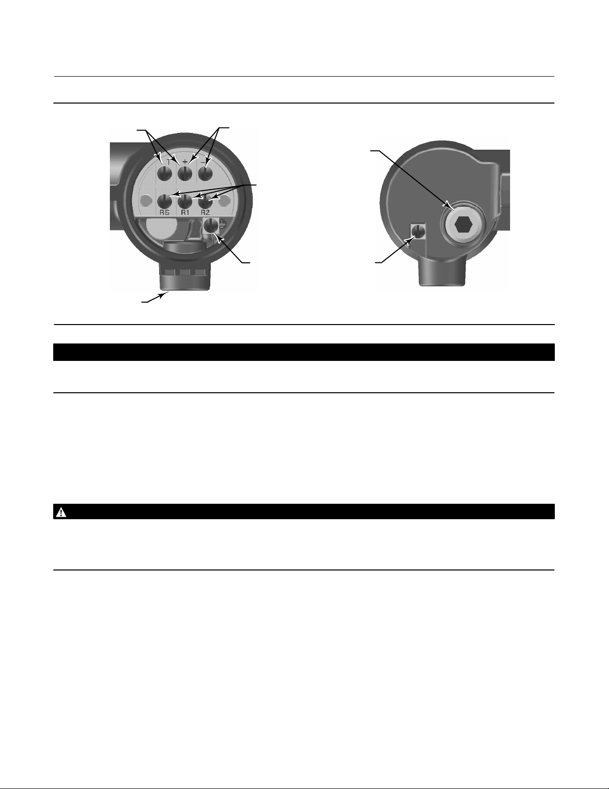
Figure 2‐11. Digital Level Controller Terminal Box
TEST CONNECTIONS
4‐20 mA LOOP
CONNECTIONS
Instruction Manual
D102748X012
1/2 NPT
CONDUIT
CONNECTION
RTD
CONNECTIONS
EXTERNAL
GROUND
CONNECTION
REAR VIEW
W8041
1/2 NPT
CONDUIT
CONNECTION
INTERNAL
GROUND
CONNECTION
FRONT VIEW
CAUTION
Do not apply loop power across the T and + terminals. This can destroy the 1 Ohm sense resistor in the terminal box. Do not
apply loop power across the Rs and — terminals. This can destroy the 50 Ohm sense resistor in the electronics module.
When wiring to screw terminals, the use of crimped lugs is recommended. Tighten the terminal screws to ensure that
good contact is made. No additional power wiring is required. All digital level controller covers must be fully engaged
to meet explosion proof requirements. For ATEX approved units, the terminal box cover set screw must engage one of
the recesses in the terminal box beneath the terminal box cover.
Grounding
WARNING
Personal injury or property damage can result from fire or explosion caused by the discharge of static electricity when
flammable or hazardous gases are present. Connect a 14 AWG (2.1 mm
and earth ground when flammable or hazardous gases are present. Refer to national and local codes and standards for
grounding requirements.
2
) ground strap between the digital level controller
The digital level controller will operate with the current signal loop either floating or grounded. However, the extra
noise in floating systems affects many types of readout devices. If the signal appears noisy or erratic, grounding the
current signal loop at a single point may solve the problem. The best place to ground the loop is at the negative
terminal of the power supply. As an alternative, ground either side of the readout device. Do not ground the current
signal loop at more than one point.
Shielded Wire
Recommended grounding techniques for shielded wire usually call for a single grounding point for the shield. You can
either connect the shield at the power supply or to the grounding terminals, either internal or external, at the
instrument terminal box shown in figure 2‐11.
24
Page 25

DLC3010 Digital Level Controller
Instruction Manual
D102748X012
Installation
August 2020
Power/Current Loop Connections
Use ordinary copper wire of sufficient size to ensure that the voltage across the digital level controller terminals does
not go below 12.0 volts DC. Connect the current signal leads as shown in figure 2‐9. After making connections,
recheck the polarity and correctness of connections, then turn the power on.
RTD Connections
An RTD that senses process temperatures may be connected to the digital level controller. This permits the instrument
to automatically make specific gravity corrections for temperature changes. For best results, locate the RTD as close to
the displacer as practical. For optimum EMC performance, use shielded wire no longer than 3 meters (9.8 feet) to
connect the RTD. Connect only one end of the shield. Connect the shield to either the internal ground connection in
the instrument terminal box or to the RTD thermowell. Wire the RTD to the digital level controller as follows (refer to
figure 2‐11):
Two‐Wire RTD Connections
1. Connect a jumper wire between the RS and R1 terminals in the terminal box.
2. Connect the RTD to the R1 and R2 terminals.
Note
During Manual Setup
of 1 ohm.
, you must specify the connecting wire resistance for a 2‐wire RTD. 250 feet of 16 AWG wire has a resistance
Three‐Wire RTD Connections
1. Connect the 2 wires which are connected to the same end of the RTD to the RS and R1 terminals in the terminal
box. Usually these wires are the same color.
2. Connect the third wire to terminal R2. (The resistance measured between this wire and either wire connected to
terminal RS or R1 should read an equivalent resistance for the existing ambient temperature. Refer to the RTD
manufacturer's temperature to resistance conversion table.) Usually this wire is a different color from the wires
connected to the RS and R1 terminals.
Communication Connections
WARNING
Personal injury or property damage caused by fire or explosion may occur if this connection is attempted in an area which
contains a potentially explosive atmosphere or has been classified as hazardous. Confirm that area classification and
atmosphere conditions permit the safe removal of the terminal box cap before proceeding.
The Field Communicator interfaces with digital level controller from any wiring termination point in the 4–20 mA loop
(except across the power supply). If you choose to connect the HART communicating device directly to the
instrument, attach the device to the loop + and - terminals inside the terminal box to provide local communications
with the instrument.
25
Page 26

DLC3010 Digital Level Controller
Installation
August 2020
Instruction Manual
D102748X012
Test Connections
WARNING
Personal injury or property damage caused by fire or explosion may occur if the following procedure is attempted in an
area which contains a potentially explosive atmosphere or has been classified as hazardous. Confirm that area classification
and atmosphere conditions permit the safe removal of the terminal box cap before proceeding.
Test connections inside the terminal box can be used to measure loop current across an internal 1 ohm resistor.
1. Remove the terminal box cap.
2. Adjust the test meter to measure a range of 0.001 to 0.1 volts.
3. Connect the positive lead of the test meter to the + connection and the negative lead to the T connection inside the
terminal box.
4. Measure Loop current as:
Voltage (on test meter) 1000 = milliamps
example:
Test meter Voltage X 1000 = Loop Milliamps
0.004 X1000 = 4.0 milliamperes
0.020 X 1000 = 20.0 milliamperes
5. Remove test leads and replace the terminal box cover.
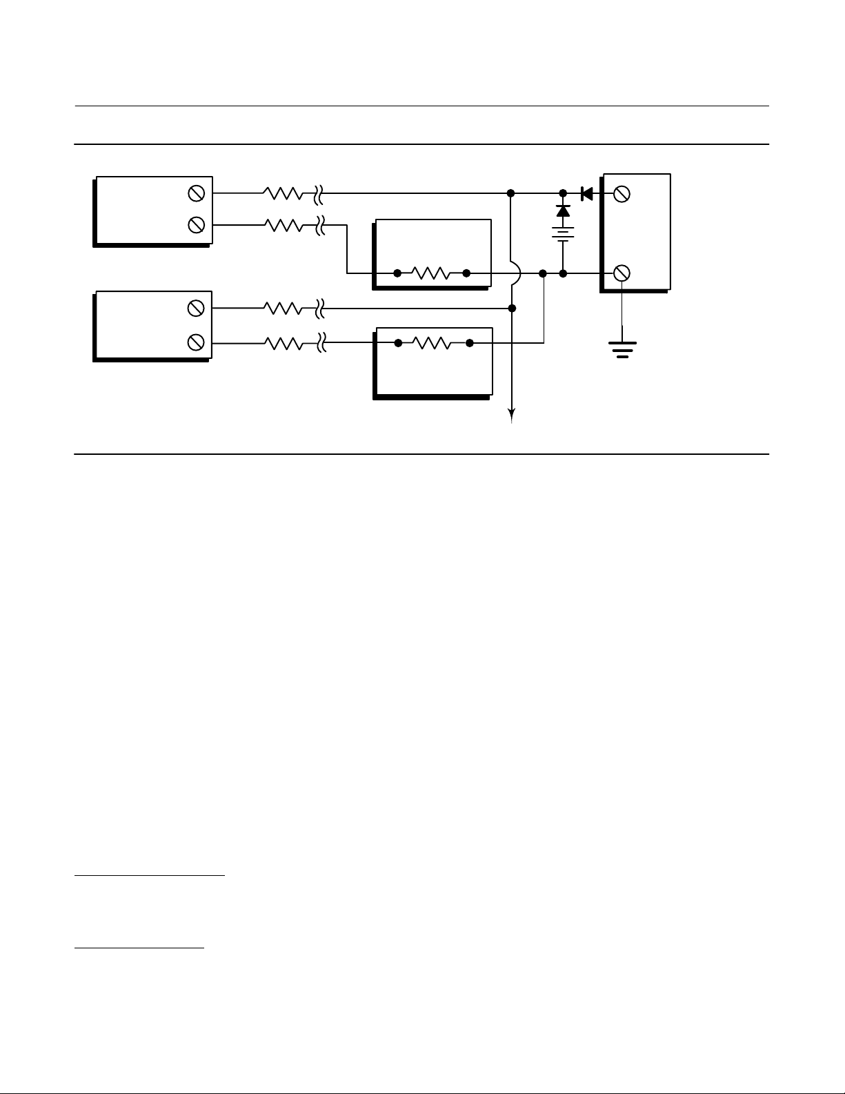
Multichannel Installations
You can connect several instruments to a single master power supply as shown in figure 2‐12. In this case, the system
may be grounded only at the negative power supply terminal. In multichannel installations where several instruments
depend on one power supply, and the loss of all instruments would cause operational problems, consider an
uninterruptible power supply or a back‐up battery. The diodes shown in figure 2‐12 prevent unwanted charging or
discharging of the back‐up battery. If several loops are connected in parallel, make sure the net loop impedance does
not reach levels that would prevent communication.
26
Page 27
Instruction Manual
D102748X012
Figure 2‐12. Multichannel Installations
R
Lead
+
Instrument
No. 1
+
-
-
R
Lead
Readout
Device No. 1
DLC3010 Digital Level Controller
+
+
DC Power
Battery
Backup
-
Supply
-
Installation
August 2020
Instrument
No. 2
E0364
+
R
Lead
-
R
Lead
Readout
Device No. 2
Between
230 and 600
if no Load Resistor
To Additional
Instruments
Note that to provide a 4‐20 mA analog output signal, the DLC3010 must use HART polling address 0. Therefore, if a
multichannel installation is used with all transmitters in 4‐20 mA output mode, some means must be provided to
isolate an individual transmitter for configuration or diagnostic purposes. A multichannel installation is most useful if
the instruments are also in multi‐drop mode and all signaling is done by digital polling.
Alarm Jumper
Each digital level controller continuously monitors its own performance during normal operation. This automatic
diagnostic routine is a timed series of checks repeated continuously. If diagnostics detect a failure in the electronics,
the instrument drives its output to either below 3.70 mA or above 22.5 mA, depending on the position (HI/LO) of the
alarm jumper.
An alarm condition occurs when the digital level controller self‐diagnostics detect an error that would render the
process variable measurement inaccurate, incorrect, or undefined, or if the PV violates a user-defined alert threshold
while a HiHi or LoLo PV monitor is enabled. At this point the analog output of the unit is driven to a defined level either
above or below the nominal 4‐20 mA range, based on the position of the alarm jumper.
On encapsulated electronics 14B5483X042 and earlier, if the jumper is missing, the alarm is indeterminate, but usually
behaves as a FAIL LOW selection. On encapsulated electronics 14B5483X052 and later, the behavior will default to
FAIL HIGH when the jumper is missing.
Alarm Jumper Locations
Without a meter installed
The alarm jumper is located on the front side of the electronics module on the electronics side of the digital level
controller housing, and is labeled FAIL MODE.
With a meter installed
The alarm jumper is located on the LCD faceplate on the electronics module side of the digital level controller housing,
and is labeled FAIL MODE.
27
Page 28

DLC3010 Digital Level Controller
Installation
August 2020
Instruction Manual
D102748X012
Changing Jumper Position
WARNING
Personal injury or property damage caused by fire or explosion may occur if the following procedure is attempted in an
area which contains a potentially explosive atmosphere or has been classified as hazardous. Confirm that area classification
and atmosphere conditions permit the safe removal of the instrument cover before proceeding.
Use the following procedure to change the position of the alarm jumper:
1. If the digital level controller is installed, set the loop to manual.
2. Remove the housing cover on the electronics side. Do not remove the cover in explosive atmospheres when the
circuit is alive.
3. Set the jumper to the desired position.
4. Replace the cover. All covers must be fully engaged to meet explosion proof requirements. For ATEX approved
units, the set screw on the transducer housing must engage one of the recesses in the cover.
Loop Test
Field Communicator Service Tools > Maintenance > Tests > Loop Test (3-4-1-2)
Loop test can be used to verify the controller output, the integrity of the loop, and the operations of any recorders or
similar devices installed in the loop. To initiate a loop test, perform the following procedure:
1. Connect a reference meter to the controller. To do so, either connect the meter to the test connections inside the
terminal box (see the Test Connections procedure) or connect the meter in the loop as shown in figure 2‐9.
2. Access Loop Test.
3. Select OK after you set the control loop to manual.
The Field Communicator displays the loop test menu.
4. Select a discreet milliamp level for the controller to output. At the “Choose analog output” prompt, select 4 mA,
20 mA, or Other to manually input a value between 4 and 20 milliamps.
5. Check the reference meter to verify that it reads the value you commanded the controller to output. If the readings
do not match, either the controller requires an output trim, or the meter is malfunctioning.
After completing the test procedure, the display returns to the loop test screen and allows you to choose another
output value or end the test.
28
Page 29
DLC3010 Digital Level Controller
Instruction Manual
D102748X012
Installation
August 2020
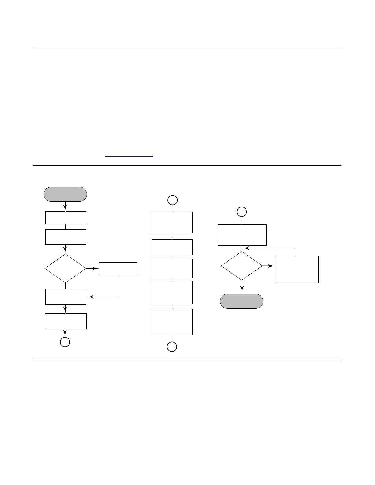
Installation in Conjunction with a Rosemount 333 HART Tri‐Loop
HART‐to‐Analog Signal Converter
Use the DLC3010 digital level controller in operation with a Rosemount 333 HART Tri-Loop HART‐to‐Analog Signal
Converter to acquire an independent 4‐20 mA analog output signal for the process variable, % range, electronics
temperature, and process temperature. The Tri‐Loop divides the digital signal and outputs any or all of these variables
into as many as three separate 4‐20 mA analog channels.
Refer to figure 2‐13 for basic installation information. Refer to the 333 HART Tri‐Loop HART‐to‐Analog Signal
Converter Product Manual (00809-0100-4754
Figure 2‐13. HART Tri‐Loop Installation Flowchart
START HERE
) for complete installation information.
Unpack the
HART Tri‐Loop
Review the
HART Tri‐Loop
Product Manual
Digital level
controller
Installed?
Yes
Set the digital
level controller
Burst Option
Set the digital
level controller
Burst Mode
E0365
No
Install the digital
level controller.
Install the HART
Tri‐Loop. See
HART Tri‐Loop
Product Manual
Mount the HART
Tri‐Loop to the
DIN rail.
Wire the digital
level controller to
the HART Tri‐Loop.
Install Channel 1
wires from HART
Tri‐Loop to the
control room.
(Optional)
Install Channel
2 and3 wires from
HART Tri‐Loop to
the control room.
Configure the HART
Tri‐Loop to receive
digital level controller
burst commands
Pass system
test?
Yes
DONE
No
troubleshooting
procedures in HART
Tri‐Loop product
Check
manual.
29
Page 30
DLC3010 Digital Level Controller
(1)
Installation
August 2020
Instruction Manual
D102748X012
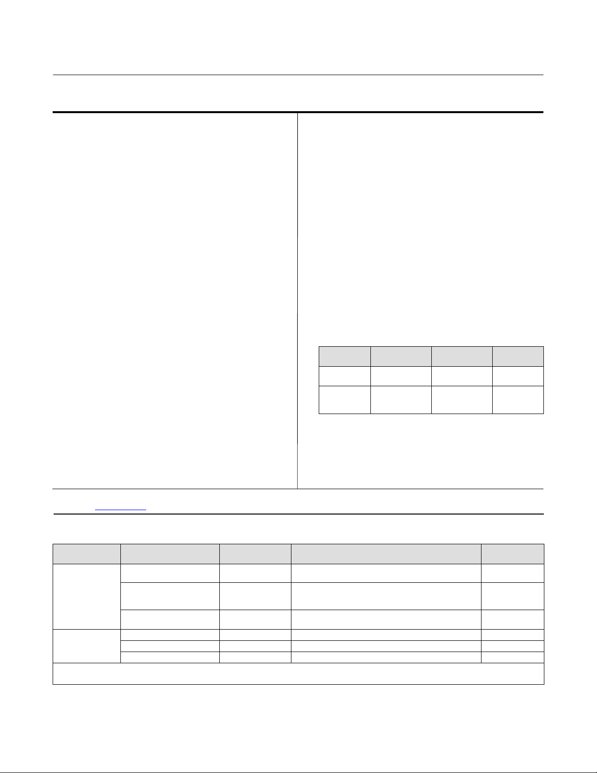
Commissioning the Digital Level Controller for use with the HART Tri‐Loop
To prepare the digital level controller for use with a 333 HART Tri‐Loop, you must configure the digital level controller
to burst mode, and select the dynamic variables to burst. In burst mode, the digital level controller provides digital
information to the HART Tri‐Loop HART‐to‐Analog Signal Converter. The HART Tri‐Loop converts the digital
information to a 4‐20 mA analog signal. The HART Tri‐Loop divides the signal into separate 4‐20 mA loops for the
primary (PV), secondary (SV), and tertiary (TV) variables. Depending upon the burst option selected, the digital level
controller will burst the variables as shown in table 2‐1.
The DLC3010 status words are available in the HART Burst messages. However, the Tri‐Loop cannot be configured to
monitor them directly.
To commission a DLC3010 digital level controller for use with a HART Tri‐Loop, perform the following procedure.
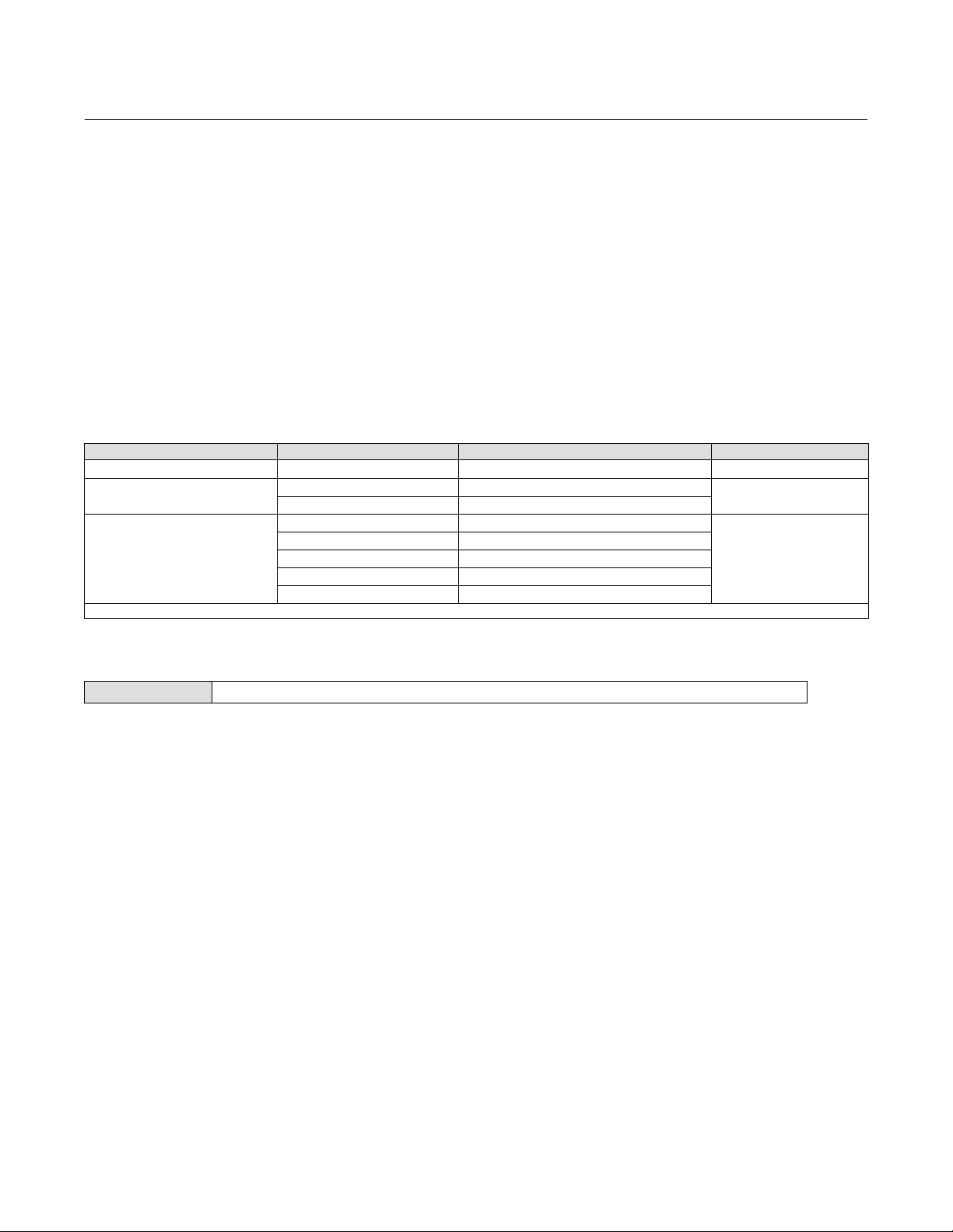
Table 2‐1. Burst Variables Sent by the FIELDVUE DLC3010
Burst Option Variable Variable Burst
Read PV Primary Process variable (EU) 1
Read PV mA and % Range
Read Dynamic Vars
1. EU—engineering units; mA—current in milliamperes; %—percent of span
Loop Current Process variable (mA)
Percent Range Process variable Percent range (%)
Loop Current Process variable (mA)
Primary Process variable (EU)
Secondary Electronics temperature (EU)
Tertiary Process temperature (EU)
Quaternary Not used
Burst Command
2
3
Set the Burst Operation
Field Communicator Configure > Manual Setup > Communications (2-2-6)
1. Access Burst Option.
2. Select the desired burst option and press ENTER
3. Access Burst Mode and select On to enable burst mode. Press ENTER.
4. Select SEND to download the new configuration information to the digital level controller.
30
Page 31

Instruction Manual
D102748X012
Section 3 Overview3-3-
Overview
Field Communicator Overview (1)
Device Status
Good There are no active alerts and instrument is In Service.
Failed The highest severity active alert is in the Failed category.
Maintenance The highest severity active alert is in the Maintenance category.
Advisory The highest severity active alert is in the Advisory category.
DLC3010 Digital Level Controller
Overview
August 2020
Comm Status
Polled Communication with digital level controller is established. Burst mode is turned off.
Burst Provides continuous communication from the digital level controller. Burst mode applies only to the
transmission of burst mode data and does not affect the way other data is accessed.
Liquid Level,
Interface Level, or
Liquid Density
Indicates the type of measurement either level, interface (the interface of two liquids of different specific gravities), or
density (measures the liquid specific gravity). The process variable displayed and measured depends on the entry for
“PV is” under PV Setup.
Process Temperature
When the process temperature is manually entered, indicates the target process temperature entered in the device
configuration.
When the process temperature is NOT manually entered, process temperature represents the temperature measured
by an RTD located in the process fluid.
Analog Output
Indicates the current value for the analog output of the instrument being commanded by the firmware, in
milliamperes.
Calibration / Ranging
Primary
See the Calibration section, starting on page 58, for Primary calibration information.
31
Page 32

DLC3010 Digital Level Controller
Overview
August 2020
Instruction Manual
D102748X012
Secondary
See the Calibration section, starting on page 58, for Secondary calibration information.
Ranging
D Upper Sensor Limit indicates the maximum usable value for a Range Value.
D Lower Sensor Limit indicates the minimum usable value for a Range Value.
D Minimum Span is the difference between the Upper Range Value and the Lower Range Value below which
amplification of instrument errors may become a concern. This effect should be considered when sizing displacer /
torque tube.
D Upper Range Value defines the operational end point from which the Analog Value and the 100% point of the
percent range are derived.
D Lower Range Value defines the operational end point from which the Analog Value and the 0% point of the percent
range are derived.
D Analog Output Action is set to DIRECT when analog output increases with increasing process signal, and to REVERSE
when analog output decreases with increasing process signal.
D Change Action allows you to change the output action by swapping values of the Upper Range Value and Lower
Range Value. Action is DIRECT if the Upper Range Value is greater than the lower range value. Action is REVERSE if
Lower Range Value is greater than Upper Range Value.
D Level Offset is the Primary Variable value you want the instrument to report when physical level is at the bottom of
displacer. It is only available in Level or Interface measurement mode.
D Set Level Offset adding a level offset permits the process variable value in engineering units to be reported with
respect to a reference point other than the bottom of the displacer (see figure 3‐1). Examples include: bottom of
the process vessel, the process set point, or sea level. Set Level Offset is only available in Level or Interface
measurement mode. Follow the prompts on the Field Communicator to enter the offset value. The procedure will
offer to shift the range values and alert thresholds by the amount of the level offset for you. This will keep the 4-20
mA output aligned with the top and bottom of the displacer. If you have already shifted the range values and alert
thresholds to account for the effect of the offset you are adding select No when asked if you want to 'Proceed
changing range values and alert thresholds'.
Figure 3‐1. Example of the Use of Level Offset
URV
(10 FEET)
DISPLACER
32
LRV
(6 FEET)
E0368
LEVEL
OFFSET
(6 FEET)
Page 33

DLC3010 Digital Level Controller
Instruction Manual
D102748X012
Overview
August 2020
Device Information
Identification
Follow the prompts on the Field Communicator display to view the following information.
D Tag (also called HART tag) is a unique name (up to eight characters) that identifies the physical instrument.
D Distributor identifies the distributor of the instrument.
D Model identifies the instrument model; ie. DLC3010.
D Serial Numbers
Device ID— each instrument has a unique Device Identifier. The Device ID provides additional security to prevent
this instrument from accepting commands meant for other instruments.
Instrument Serial Number— enter or view the serial number on the instrument nameplate, up to 12 characters.
Sensor Serial Number— enter or view the sensor serial number. The sensor serial number is found on the sensor
nameplate.
Final Assembly Number— a number that can be used to identify the instrument and sensor combination.
D Date is a userdefined variable that provides a place to save the date of the last revision of configuration or
calibration information.
D Description is a longer userdefined electronic label to assist with more specific controller identification than is
available with the HART tag.
D Message is a user‐defined means for identifying individual controllers in multi‐controller environments.
Revisions
Follow the prompts on the Field Communicator display to view revision information.
D Universal indicates the revision number of the HART Universal Commands which are used as the communications
protocol for the instrument.
D Device indicates the revision of the external interface specification that governs communication between the Field
Communicator and the instrument.
D Firmware indicates the revision number of the Fisher software in the instrument.
D Hardware indicates the revision number of the Fisher instrument hardware.
D DD Information is the revision level of the Device Description used by the Field Communicator while
communicating with the instrument.
33
Page 34

DLC3010 Digital Level Controller
Overview
August 2020
Instruction Manual
D102748X012
Alarm Type and Security
D Alarm Configuration
Alarm Jumper indicates the analog output commanded in an alarm condition, either Fail Lo (3.7 mA) or
Fail Hi (22.5 mA).
Notes
Consider the effect of an alarm annunciation on the process and set alarm jumper position accordingly.
When Output Action is 'Direct':
A Hi alarm setting will result in an alarm-state output consistent with a very high process.
A Lo alarm setting will result in an alarm-state output consistent with a very low process.
When Output Action is 'Reverse', these relationships are swapped.
This variable is not updated dynamically, Select Refresh Jumper if you have moved the jumper.
If the network is in Multi-Drop alarm annunciation is disabled and the device is not directly driving any effector, so jumper setting is
not a concern.
Refresh Jumper allows you read the alarm jumper position.
Signal Levels displays the signal saturation or alarm conditions via Analog Output.
D Security
To setup and calibrate the instrument, Write Protect must be set to Not Write Protected. (Write protection is reset by a
power cycle. If you have just powered up the instrument Writes will be enabled by default.) In AMS, go to Device
Information in the Overview page. Select the Alarm Type and Security tab to change Write Protect.
Write Protect displays the protection setting; “Not Write Protected” allows configuration and calibration of the
instrument, “Write Protected” indicates that configuration and calibration are not currently allowed.
Change Protection allows you to enable or disable configuration and calibration of the instrument.
34
Page 35

DLC3010 Digital Level Controller
Instruction Manual
D102748X012
Configuration
August 2020
Section 4 Configuration and Calibration 4-4-
Initial Setup
If a DLC3010 digital level controller ships from the factory mounted on a 249 sensor, initial setup and calibration is not
necessary. The factory enters the sensor data, couples the instrument to the sensor, and calibrates the instrument and
sensor combination.
Note
If you received the digital level controller mounted on the sensor with the displacer blocked, or if the displacer is not connected,
the instrument will be coupled to the sensor and the lever assembly unlocked. To place the unit in service, if the displacer is
blocked, remove the rod and block at each end of the displacer and check the instrument calibration. (If the “factory cal” option
was ordered, the instrument will be precompensated to the process conditions provided on the requisition, and will not appear to
be calibrated if checked against room temperature 0 and 100% water level inputs).
If the displacer is not connected, hang the displacer on the torque tube.
If you received the digital level controller mounted on the sensor and the displacer is not blocked (such as in skid mounted
systems), the instrument will not be coupled, to the sensor, and the lever assembly will be locked. Before placing the unit in
service, couple the instrument to the sensor, then unlock the lever assembly.
When the sensor is properly connected and coupled to the digital level controller, establish the zero process condition and run the
appropriate zero calibration procedure under Partial Calibration. The Torque Rate should not need to be re-calibrated.
To review the configuration data entered by the factory, connect the instrument to a 24 VDC power supply as shown in
figure 2‐9. Connect the Field Communicator to the instrument and turn it on. Go to Configure and review the data
under Manual Setup, Alert Setup, and Communications. If your application data has changed since the instrument was
factory‐configured, refer to the Manual Setup section for instructions on modifying configuration data.
For instruments not mounted on a level sensor or when replacing an instrument, initial setup consists of entering
sensor information. The next step is coupling the sensor to the digital level controller. When the digital level controller
and sensor are coupled, the combination may be calibrated.
Sensor information includes displacer and torque tube information, such as:
D Length units (meters, inches, or centimeters)
D Volume units (cubic inches, cubic millimeters, or milliliters)
D Weight units (kilograms, pounds, or ounce)
D Displacer Length
D Displacer Volume
D Displacer Weight
D Displacer Driver Rod Length (moment arm) (see table 4‐1)
35
Page 36

DLC3010 Digital Level Controller
Configuration
August 2020
D Torque Tube Material
Note
A sensor with an N05500 torque tube may have NiCu on the nameplate as the torque tube material.
D Instrument mounting (right or left of displacer)
D Measurement Application (level, interface, or density)
Instruction Manual
D102748X012
Configuration Advice
Guided Setup directs you through initialization of configuration data needed for proper operation. When the
instrument comes out of the box, the default dimensions are set for the most common Fisher 249 construction, so if
any data is unknown, it is generally safe to accept the defaults. The mounting sense 'instrument left or right of
displacer' - is important for correct interpretation of positive motion. The torque tube rotation is clockwise with rising
level when the instrument is mounted to the right of the displacer, and counterclockwise when mounted to the left of
the displacer. Use Manual Setup to locate and modify individual parameters when they need to be changed.
Preliminary Considerations
Write Protect
Field Communicator Overview > Device Information > Alarm Type and Security > Security > Change Protection (1-7-3-2-2)
To setup and calibrate the instrument, Write Protect must be set to Not Write Protected. Write Protect is reset by a
power cycle. If you have just powered up the instrument Writes will be enabled by default.
Guided Setup
Field Communicator Configure > Guided Setup > Instrument Setup (2-1-1)
Note
Place the loop into manual operation before making any changes in setup or calibration.
Instrument Setup is available to aid initial setup. Follow the prompts on the Field Communicator display to enter
information for the displacer, torque tube, and digital measurement units. Most of the information is available from
the sensor nameplate, shown in figure 4‐1. The moment arm is the effective length of the driver rod and depends
upon the sensor type. For a 249 sensor, refer to table 4‐1 to determine driver rod length. For a special sensor, refer to
figure 4‐2.
36
Page 37

Instruction Manual
(1)
(1)
D102748X012
Figure 4‐1. Example Sensor Nameplate
DLC3010 Digital Level Controller
Configuration
August 2020
DISPLACER
MATERIAL
23A1725‐E sht 1
E0366
SENSOR TYPE
76543210
249B
1500 PSI
103 CU‐IN
316 SST
DISPLACER
PRESSURE RATING
PSI
2 x 32 INCHES
4 3/4 LBS
K MONEL/STD
DISPLACER
VOLUME
DISPLACER
WEIGHT
285/100 F
WCB STL
MONEL
TORQUE TUBE MATERIAL
DISPLACER SIZE
(DIAMETER X LENGTH)
ASSEMBLY
PRESSURE RATING
ASSEMBLY MATERIAL
TRIM MATERIAL
Table 4‐1. Moment Arm (Driver Rod) Length
SENSOR TYPE
(2)
mm Inch
249 203 8.01
249B 203 8.01
249BF 203 8.01
249BP 203 8.01
249C 169 6.64
249CP 169 6.64
249K 267 10.5
249L 229 9.01
249N 267 10.5
249P
(CL125-CL600)
249P
(CL900-CL2500)
249VS (Special)
203 8.01
229 9.01
See serial card See serial card
249VS (Std) 343 13.5
249W 203 8.01
1. Moment arm (driver rod) length is the perpendicular distance between the vertical centerline of the displacer and the horizontal centerline of the torque tube. See figure 4‐2. If you cannot
determine the driver rod length, contact your Emerson sales office
2. This table applies to sensors with vertical displacers only. For sensor types not listed, or sensors with horizontal displacers, contact your Emerson sales office for the driver rod length. For
other manufacturers' sensors, see the installation instructions for that mounting.
and provide the serial number of the sensor.
MOMENT ARM
1. Enter displacer length, weight, volume units and values, and driver rod (moment arm) length (in the same units
chosen for displacer length) when prompted.
2. Choose Instrument Mounting (left or right of displacer, refer to figure 2‐5).
3. Choose Torque Tube Material.
37
Page 38

DLC3010 Digital Level Controller
Configuration
August 2020
Instruction Manual
D102748X012
4. Select the measurement application (liquid level, interface level, or liquid density).
Note
For interface applications using standard hardware, if the 249 is not installed on a vessel, or if the cage can be isolated, calibrate
the instrument with weights, water, or other standard test fluid, in level mode. After calibrating in level mode, the instrument can
be switched to interface mode. Then, enter the actual process fluid specific gravity(s) and range values. For an interface
application with an overweight displacer, see the section of this manual on "Calibration with an Overweight Displacer".
If the 249 sensor is installed and must be calibrated in the actual process fluid(s) at operating conditions, enter the final
measurement mode and actual process fluid data now.
Figure 4‐2. Method of Determining Moment Arm from External Measurements
VESSEL
VERTICAL C
OF DISPLACER
L
MOMENT
ARM LENGTH
HORIZONTAL C
OF TORQUE TUBE
L
a. If you choose “Liquid Level” or “Interface Level,” the default process variable units are set to the same units
chosen for displacer length. You are prompted to key in the level offset. Range values will be initialized based on
Level Offset and displacer size. The default upper range value is set to equal the displacer length and the default
lower range value is set to zero when the level offset is 0.
b. If you choose “Liquid Density,” the default process variable units are set to “SGU” (Specific Gravity Units). The
default upper range value is set to “1.0” and the default lower range value is set to “0.1”.
5. Select the desired output action: Direct or Reverse
Choosing “reverse acting” will swap the default values of the upper and lower range values (the process variable values
at 20 mA and 4 mA). In a reverse acting instrument, the loop current will decrease as the process variable value
increases.
6. You are given the opportunity to modify the default value for the process variable engineering units.
7. You are then given the opportunity to edit the default values that were entered for the upper range value (PV Value
at 20 mA) and lower range value (PV Value at 4 mA).
8. The default values of the alarm variables will be set as follows:
(Span = Upper Range Value - Lower Range Value
Direct‐Acting Instrument
Alarm Variable Default Alarm Value
Hi‐Hi Alarm Upper Range Value
Hi Alarm 95% span + Lower Range Value
Lo Alarm 5% span + Lower Range Value
Lo‐Lo Alarm Lower Range Value
38
(Span = Lower Range Value - Upper Range Value
Alarm Variable Default Alarm Value
Hi‐Hi Alarm Lower Range Value
Hi Alarm 95% span + Upper Range Value
Lo Alarm 5% span + Upper Range Value
Lo‐Lo Alarm Upper Range Value
Reverse‐Acting Instrument
Page 39

DLC3010 Digital Level Controller
Instruction Manual
D102748X012
Configuration
August 2020
PV alert thresholds are initialized at 100%, 95%, 5% and 0% span.
PV alert deadband is initialized to 0.5% span.
PV alerts are all disabled. Temperature alerts are enabled.
D If Liquid Density mode was chosen, setup is complete.
D If Interface Level or Liquid Level mode was chosen, you are advised that process fluid data must be configured. You
have the options of entering constant SG values or loading default steam tables during setup, or exiting the
procedure and manually configuring the process data later.
Note
If you are using water or weights for calibration, enter a specific gravity of 1.0 SGU. For other test fluids, enter the specific gravity
of the fluid used.
Detailed configuration of the process fluid and temperature compensation is provided in Configure > Manual Setup >
Process Conditions > Fluid(s).
Coupling
If the digital level controller is not already coupled to the sensor, perform the following procedure to couple the digital
level controller to the sensor.
1. Slide the access handle to the locked position to expose the access hole. Press on the back of the handle as shown in
figure 2‐4 then slide the handle toward the front of the unit. Be sure the locking handle drops into the detent.
2. Set the displacer to the lowest possible process condition, (i.e. lowest water level or minimum specific gravity) or
replace the displacer by the heaviest calibration weight.
Note
Interface or density applications with displacer/torque tube sized for a small total change in specific gravity are designed to be
operated with the displacer always submerged. In these applications, the torque rod is sometimes resting on a stop while the
displacer is dry. The torque tube does not begin to move until a considerable amount of liquid has covered the displacer. In this
case, couple with the displacer submerged in the fluid with the lowest density and the highest process temperature condition, or
with an equivalent condition simulated by the calculated weights.
If the sizing of the sensor results in a proportional band greater than 100% (total expected rotational span greater than 4.4
degrees), couple the transmitter to the pilot shaft while at the 50% process condition to make maximum use of available
transmitter travel ($6_). The Capture Zero procedure is still performed at the zero buoyancy (or zero differential buoyancy)
condition.
3. Insert a 10 mm deep well socket through the access hole and onto the torque tube shaft clamp nut. Tighten the
clamp nut to a maximum torque of 2.1 NSm (18 lbfSin).
4. Slide the access handle to the unlocked position. (Press on the back of the handle as shown in figure 2‐4 then slide
the handle toward the rear of the unit.) Be sure the locking handle drops into the detent.
39
Page 40

DLC3010 Digital Level Controller
Configuration
August 2020
Instruction Manual
D102748X012
Manual Setup
The DLC3010 digital level controller has the capability to communicate via the HART protocol. This section describes
the advanced features that can be accessed with the Field Communicator.
Note
Changing setup parameters may require enabling writing to the instrument with the Field Communicator (Overview > Device
Information > Alarm Type and Security > Security > Change Protection). Select Not Write Protected to enable writing setup and
calibration data, or select Write Protected to disable writing data. Note that cycling power will clear the write lock condition to “Not
Write Protected”.
Sensor
Field Communicator Configure > Manual Setup > Sensor (2-2-1)
Sensor Units
D Length selects the units of measure for the displacer length (in feet, meters, inches, or centimeters).
D Volume selects the units of measure for the displacer volume (in liters, cubic inches, cubic millimeters, or milliliters).
D Weight selects the units of measure for the displacer weight (in grams, kilograms, pounds, or ounces).
D Torque Rate selects the torque rate units (in lbf‐in per deg—pounds‐force inches per degree rotation; newton‐m per
deg—newton‐meters per degree rotation; or dyne‐cm per deg—dyne-centimeters per degree rotation.
D Temperature selects either degC (degrees centigrade) or degF (degrees Fahrenheit) for the temperature units.
Sensor Dimensions
Dimensions can be found on the sensor name plate as shown in figure 4‐1.
D Displacer Length— Enter the displacer length from the sensor nameplate.
D Displacer Volume— Enter the displacer volume from the sensor nameplate.
D Displacer Weight— Enter the displacer weight from the sensor nameplate.
D Driver Rod Length— Enter the displacer rod length. The displacer rod length depends upon the sensor type. For a
249 sensor, obtain the displacer rod length from table 4‐1 or from the Field Communicator Help. Refer to figure 4‐2
to physically measure this value.
40
Page 41

DLC3010 Digital Level Controller
Instruction Manual
D102748X012
Configuration
August 2020
Torque Tube
D TT Material displays the torque tube material currently stored in the instrument.
Note
A sensor with an N05500 torque tube may have NiCu on the nameplate as the torque tube material.
D Change Material— selecting a material in this procedure loads the default torque rate temperature compensation
for the specified torque tube material.
D Edit Compensation
TT Compensation— Each temperature-coefficient data pair may be edited.
If using fewer than 10 data pairs, a “0.0” entry in the dependent variable slot terminates the table entry process.
The firmware treats a zero entry in the dependent variable slot as an indication that the previous data point was the
end of the table and that interpolation ends at that point. If only one data pair exists before the pair with the 0.0
dependent variable entry, the table is flat. It provides a constant output across the entire temperature range.
Torque Comp Plot displays a graph of the compensation table.
Pre-compensate Torque Rate— The stiffness of the torque tube varies with process temperature. The firmware
does not implement dynamic temperature compensation of the torque rate. However, the compensation tables
for this effect are stored in the device. The “Pre-compensate Torque Rate” procedure allows you to apply a fixed
compensation factor, based on the target process temperature, to the torque rate value stored in the instrument.
For example, if the sensor was calibrated at 70_F or a theoretical torque rate valid at 70_F was manually entered in
the configuration, but the target process operating condition is 375_F, this procedure will compute an appropriate
correction factor from the table for the selected torque tube material, and modify the stored torque rate by that
factor. The calibration should then be more accurate at the target process temperature (with a corresponding
degradation at 70_F). It is recommended that you document this action by entering appropriate text in the
Description and/or Message fields of the device configuration, to facilitate reversing the compensation later, and to
help prevent it from being applied twice.
D Torque Rate displays the torque rate currently stored in the instrument.
D Change Torque Rate applies a rough, theoretical calibration to the torque tube when manipulation of the input is
impossible
Instrument Mounting
Specify whether the instrument is mounted to the right or left of the displacer. See figure 2‐5.
Note
While facing DLC3010 Display, report whether DLC3010 is mounted to left or right of displacer. This determines positive sense of
torque tube rotation for increasing buoyancy.
Sensor Damping
Configure the input filter.
Time constant for the input filter, in seconds, for the A/D measurement. The filter is applied before PV processing,
after the A/D conversion. Range is 0 to 16 seconds in 0.1 second increments. The default value is 0.0 seconds. To
41
Page 42

DLC3010 Digital Level Controller
Configuration
August 2020
Instruction Manual
D102748X012
disable the filter, set the time constant to 0 seconds. This filter is provided for extreme input noise situations. Use of
this filter normally should not be necessary.
Net instrument response is a combination of analog input filtering, sensor damping, PV damping, and output filtering.
Variables
Field Communicator Configure > Manual Setup > Variables (2-2-2)
View or edit Variable information.
Primary Variable
Secondary Variable
Third Variable
D PV, SV or TV display the PV, SV, or TV assignment, as selected, currently stored in the instrument.
D Units— Permits changing the units.
For density measurement:
g/cm
kg/m
3
—grams per cubic centimeter
3
—kilograms per cubic meter
lb/gal—pounds per gallon
lb/ft
3
—pounds per cubic foot
g/mL—grams per milliliter
kg/L—kilograms per liter
g/L—grams per liter
lb/in
3
—pounds per cubic inch
SGU—specific gravity units
For level and interface measurement:
ft—feet
m—meters
in—inches
cm—centimeters
mm—millimeters
For TV and SV the units are read-only, as they are controlled by the Temperature Units selection in the Sensor Units
menu.
D Damping changes the response time of the controller to smooth variations in output readings caused by rapid
changes in input. Determine the appropriate damping setting based on the necessary response time, signal
stability, and other requirements of the loop dynamics of your system. The default damping value is 0.2 seconds.
and can be reset to any value between 0 and 16 seconds in 0.1 second increments. When set to 0, the damping
function is off. Damping for SV and TV is fixed at 60 seconds and is displayed for information only.
Net instrument response is a combination of analog input filtering, sensor damping, PV damping, and output
filtering.
42
Page 43

DLC3010 Digital Level Controller
Instruction Manual
D102748X012
Configuration
August 2020
Change PV
Allow you to change the PV assignment. Select Level Units if the PV is level, Interface Units if the PV is Interface, or
Density Units if the PV is Density.
Note
If the PV assignment is changing to Level or Interface, go to the Process Fluid(s) menu and edit the configuration data for fluid
density before returning the loop to Auto.
Ranging
Field Communicator Configure > Manual Setup > Ranging (2-2-3)
Follow the prompts on the Field Communicator to view or edit ranging information.
D Upper Sensor Limit indicates the maximum usable value for a Range Value.
D Lower Sensor Limit indicates the minimum usable value for a Range Value.
D Minimum Span is the difference between the Upper Range Value and the Lower Range Value below which
amplification of instrument errors may become a concern. This effect should be considered when sizing displacer /
torque tube.
D Upper Range Value defines the operational end point from which the Analog Value and the 100% point of the
percent range are derived. The device will output 20 mA when the PV is equal to the Upper Range Value.
D Lower Range Value defines the operational end point from which the Analog Value and the 0% point of the percent
range are derived. The device will output 4 mA when the PV is equal to the Lower Range Value.
D Change Action allows you to change the analog output action: Direct/Reverse. For Reverse action, the Upper Range
Value and Lower Range Value will be swapped.
D Level Offset is the Primary Variable value you want the instrument to report when physical level is at the bottom of
displacer.
Note
Level Offset and Set Level Offset are
only available in Liquid Level or Interface Level measurement mode.
D Set Level Offset adding a level offset permits the process variable value in engineering units to be reported with
respect to a reference point other than the bottom of the displacer (see figure 4‐3). Examples include: bottom of
the process vessel, the process set point, or sea level.
Follow the prompts on the Field Communicator to enter the offset value. The procedure will offer to shift the range
values and alert thresholds by the amount of the level offset for you. This will keep the 4-20 mA output aligned with
43
Page 44

DLC3010 Digital Level Controller
Configuration
August 2020
Instruction Manual
D102748X012
the top and bottom of the displacer. If you have already shifted the range values and alert thresholds to account for
the effect of the offset you are adding select No when asked if you want to 'Proceed changing range values and alert
thresholds'.
Figure 4‐3. Example of the Use of Level Offset
URV
(10 FEET)
LRV
(6 FEET)
E0368
DISPLACER
LEVEL
OFFSET
(6 FEET)
Process Conditions
Field Communicator Configure > Manual Setup > Process Conditions (2-2-4)
Follow the prompts on the Field Communicator to view or edit process condition information.
D RTD Data is visible when Process Temperature Source is not Manual Entry.
Process Temperature displays the process temperature measured by a resistance temperature detector (RTD)
located in the process fluid.
RTD Wire Resistance displays the user estimate of wiring resistance (per lead) when employing a 2-wire RTD
connection.
D Temperature Setting is a menu item that only appears when Process Temperature Source is "Manual Entry".
If a process temperature sensor (RTD) is not installed, it is possible to manually set the Digital Process Temperature
variable to the target process temperature. This value will be used by any SG-compensation tables that the user has
entered. If no compensation tables are active, the Digital Process Temperature value may be used to document the
process temperature at which the instrument was calibrated, or the process temperature for which the stored
torque rate is pre-compensated.
The Process Temperature value may be edited directly in the Temperature Setting menu item. Press Enter and then
Send to load the new value to the device.
D Process Temperature Source allows you to select the source of the process temperature parameter; Manual or
100 ohm platinum 2-wire or 3-wire RTD.
D Change Source allows you to configure an RTD to measure process temperature, or manually enter a process
temperature value to be used for Primary Variable compensation.
When configuring an RTD you must select the number of wires for an RTD; either 2 or 3.
44
Page 45

DLC3010 Digital Level Controller
Instruction Manual
D102748X012
Configuration
August 2020
For a 2‐wire RTD, you must specify the connecting wire resistance for one wire of the pair. If you know the
resistance, select Resistance and enter the resistance of the wire. 250 feet of 16 AWG wire has a resistance of 1 ohm.
If you do not know the resistance, select Compute from gauge and length and enter the wire gauge and wire length.
The procedure will present an estimate of your wire resistance along with the parameters used to compute it, and
offer you the choice of accepting the value or not. Accepting will use the computed wire resistance estimate in the
calculation of process temperature. Aborting the procedure will retain the previously configured value of wire
resistance.
D Fluids is visible in Interface Level only.
D Fluid is visible in Liquid Level only.
Upper Fluid Density
indicates the density of the upper process fluid when Primary Variable is Interface Level.
Lower Fluid Density
indicates the density of the lower process fluid when Primary Variable is Interface Level,
or
indicates the difference between densities of lower and upper process fluids when Primary Variable is Liquid Level.
View/Edit SG Tables allows you to review or edit the configuration of density temperature compensation for the
upper or lower fluid tables.
Example entries for saturated water are given in table 4‐2. Figure 4‐4 shows the curve that results when these values
are plotted.
Table 4‐2. Example Specific Gravity vs Temperature Table for Saturated Water
Data Point
10
_C _F
1
2
3
4
5
6
7
8
9
26.7
93.3
176.7
248.9
304.4
337.8
354.4
365.6
371.1
374.7
Temperature
80.0
200.0
350.0
480.0
580.0
640.0
670.0
690.0
700.0
706.5
Specific Gravity
0.9985
0.9655
0.8935
0.8040
0.7057
0.6197
0.5570
0.4940
0.4390
0.3157
45
Page 46

DLC3010 Digital Level Controller
Configuration
August 2020
Figure 4‐4. Example Saturated Water Curve Plotted with Values from Table 4‐2
TEMPERATURE _C
1.0
0.9
0.8
0.7
0.6
0.5
SPECIFIC GRAVITY
0.4
0.3
0 100 200 300 400 500 600 700
E0369
100 200 300-18 30 380
TEMPERATURE _F
Instruction Manual
D102748X012
You can enter up to 10 temperature and specific gravity pairs in the table. The table entry function is terminated by
entering zero for the specific gravity. Keep this in mind when setting up a table for a upper fluid, such as steam,
whose specific gravity approaches 0 at lower temperatures.
The resolution of the table entry for specific gravity is 5 decimal places. This means the smallest specific gravity
value you can enter is 0.00001, which should be sufficient to allow a starting temperature around 15.6 _C (60 _F)
for the steam specific gravity table.
The example set of tables given are generated by visually laying linear segments over a reference curve, and are not
guaranteed to provide any particular accuracy. They are provided to illustrate the guidelines for developing your
own table.
1. Establish a table for the fluid(s) you are using over the expected operating range of process temperature. This
allows you to make best use of the maximum of ten points to obtain the accuracy you require. If your fluid
specific gravity is very linear over the operating temperature range, two data points may be sufficient. (The
correction algorithm provides linear interpolation between data points, and bounds the result at the table end
points.)
2. Pick points closer together in regions of higher slope.
3. Pick linear segments that distribute the error equally on each side of the true curve.
Enter values in the specific gravity tables.
If using fewer than 10 data pairs, a “0.0” entry in the dependent variable slot terminates the table entry process.
The firmware treats a zero entry in the dependent variable slot as an indication that the previous data point was the
end of the table and that interpolation ends at that point. If only one data pair exists before the pair with the 0.0
dependent variable entry, the table is flat. It provides a constant output across the entire temperature range.
Enter Constant SG allows you to define fluid density/densities by constant values. No temperature compensation is
applied.
Measure SG is only visible if PV is Liquid Level.
46
Page 47

DLC3010 Digital Level Controller
Instruction Manual
D102748X012
Configuration
August 2020
If specific gravity information for the process fluid is not available, an instrument and sensor combination that has
been previously calibrated can be used to measure the fluid density. You must be able to manipulate the level and
externally measure it to have the instrument measure the specific gravity. First capture a new zero reference angle
at the zero process condition for the unknown fluid(s), then run this procedure. If the actual process application is
Level, use a test level near 100% when measuring SG. If the actual process application is interface, the best
differential SG measurement will be obtained at 50% interface level. Follow the prompts on the Field Communicator
and the following procedure to measure specific gravity:
1. Set the control loop for manual control.
2. Adjust the liquid level as close as possible to the optimum value discussed above.
3. Enter the externally measured level, in engineering units.
After you press OK on the Field Communicator, the instrument begins calculating the specific gravity. You can
then elect to use this value as the specific gravity for all level measurements. If you select No, the instrument uses
the specific gravity entered under PV Setup, or the values from the specific gravity tables.
4. When finished measuring specific gravity, return the control loop to automatic control.
View/Edit SG Tables allows you to review or edit the configuration of density temperature compensation.
Load Steam Tables is only visible if PV is Interface Level.
Table 4‐3 lists example entries for saturated steam. Figure 4‐5 is the curve that results when these values are
plotted.
Table 4‐3. Example Specific Gravity vs Temperature Table for Saturated Steam
Data Point
1
2
3
4
5
6
7
8
9
10
_C _F
126.7
210.0
271.1
304.4
326.7
343.3
357.8
365.6
371.1
374.4
Temperature
260
410
520
580
620
650
676
690
700
706
Figure 4‐5. Example Saturated Steam Curve Plotted from Values in Table 4‐3
TEMPERATURE _C
-18
0.35
0.30
0.25
0.20
0.15
0.10
SPECIFIC GRAVITY
0.05
100 200 300 375
Specific Gravity
0.00095
0.00850
0.02760
0.04900
0.07200
0.09800
0.13500
0.16800
0.21000
0.31570
0.0
0 100 200 300 400 500 600 700
E0370
TEMPERATURE _F
47
Page 48

DLC3010 Digital Level Controller
Configuration
August 2020
Instruction Manual
D102748X012
Device Identification
Field Communicator Configure > Manual Setup > Device Identification (2-2-5)
Follow the prompts on the Field Communicator display to view or edit information in the following fields.
D Tag (also called HART tag) is a unique name (up to eight characters) that identifies the physical instrument.
D Instrument Serial Number— Use this field to enter or view the serial number on the instrument nameplate, up to 12
characters.
D Sensor Serial Number— Use this field to enter or view the sensor serial number. The sensor serial number is found on
the sensor nameplate.
D Final Assembly Number— A number that can be used to identify the instrument and sensor combination.
D Date provides a place to save the date of the last revision of configuration or calibration information. It has no
impact on the operation of the controller or Field Communicator. The format, such as MM/DD/YYYY, will be
controlled by the settings of the host operating system.
D Description provides a longer user‐defined electronic label to assist with more specific controller identification than
is available with the HART tag. The descriptor may be up to 16 characters long and has no impact on the operation
of the controller or HART‐based communicator.
D Message provides the most specific user‐defined means for identifying individual controllers in multi‐controller
environments. it allows for 32 characters of information and is stored with the other configuration data. Message
has no impact on the operation of the controller or the Field Communicator.
Communications
Field Communicator Configure > Manual Setup > Communications (2-2-6)
D Polling Address— If the digital level controller is used in a point‐to‐point configuration, the Polling Address is 0.
When several devices are connected in the same loop, each device must be assigned a unique polling address. The
Polling Address may be set to a value between 0 and 15. A device with polling address greater than 0 will operate in
Multi-Drop mode, with output current fixed. Any process information from a device in Multi-Drop mode must be
obtained via HART communication.
D Burst Mode— Enabling burst mode provides continuous communication from the digital level controller.
Note
It may be difficult to make configuration adjustments to the DLC3010 while it is in burst mode, due to an increase in
communication errors. To reconfigure the device, it is advisable to first disable burst mode.
Depending upon the burst option selected, the digital level controller will burst the variables as shown in table 4‐4.
48
Page 49

DLC3010 Digital Level Controller
(1)
Instruction Manual
D102748X012
Configuration
August 2020
Table 4‐4. Burst Variables Sent by the FIELDVUE DLC3010
Burst Option Variable Variable Burst
Read PV Primary Process variable (EU) 1
Read PV mA and % Range
Read Dynamic Vars
1. EU—engineering units; mA—current in milliamperes; %—percent
Loop Current Process variable (mA)
Percent Range Process variable Percent range (%)
Loop Current Process variable (mA)
Primary Process variable (EU)
Secondary Electronics temperature (EU)
Tertiary Process temperature (EU)
Quaternary Not used
Burst Command
2
3
D Burst Option
1. Select On in the Burst Mode menu; press ENTER to enable Burst Mode.
2. Select the desired option from the Burst Option menu and press ENTER.
3. Press SEND to download the new configuration information to the digital level controller.
For the Field Communicator to be able to communicate with a device whose polling address is not 0, it must be
configured to automatically search for all or specific connected devices.
D Scan Device allows you to refresh the host copy of device configuration.
Instrument Display
Field Communicator Configure > Manual Setup > Instrument Display (2-2-7)
Follow the prompts on the Field Communicator display to view or edit what is visible in the instrument display.
D LCD Configuration— Select this parameter to indicate if the meter is installed. If the meter is physically installed,
select Installed, then send the change to the instrument. When switching the setting from 'Not Installed' to
'Installed', the meter display will be activated immediately. However, if you change the setting to 'Not Installed'
from 'Installed' just to disable the display without physically removing the meter, a device reset or power cycle will
be required before the setting takes effect. The meter must be configured as 'installed' before you can set the
display type or the decimal places.
D Display Mode is only visible if the meter is installed.
D Change Display Mode— Select the type of information the meter should display and how it should be displayed by
selecting 'Change display mode'. You can select for display:
PV displays the process variable (level, interface, or density) in engineering units.
PV/Process Temperature alternately displays the process variable in engineering units, the process temperature in
the units selected under Temp Units (PV Setup), and the degrees of torque tube rotation.
49
Page 50

DLC3010 Digital Level Controller
Configuration
August 2020
Instruction Manual
D102748X012
% Range displays the process variable as a percent of span (determined by the LRV and URV).
PV/% Range alternately displays the process variable in engineering units and the process variable in percent of
span.
D Decimal Places—Select the number of decimal places to display, up to four. Setting the value to zero puts the
display in auto‐scale mode. It will then display as many decimals places as will fit.
If PV/Proc Temp or PV/% Range is selected, the display alternates every two seconds between the selected readings.
The meter also simultaneously displays the analog output signal using a percent of scale bar graph around the
perimeter of the display face as shown in figure 4‐6, no matter what display type is selected.
Figure 4‐6. LCD Meter Display
ANALOG OUTPUT
DISPLAY
PROCESS VARIABLE VALUE
WHEN PRESENT,
INDICATES WRITE
PROTECTED
PROCESS
VARIABLE UNITS
E0371
MODE
After you have selected the desired meter settings, press SEND on the Field Communicator to download the meter
settings to the instrument.
50
Page 51

DLC3010 Digital Level Controller
Instruction Manual
D102748X012
Configuration
August 2020
Alert Setup
Note
Take care not to configure the low alert threshold for a signal to a higher value than its high threshold, or both high and low alerts
for that signal could become active at the same time.
The following menus are available for configuring Alerts.
Primary Variable
Field Communicator Configure > Alert Setup > Primary Variable (2-3-1)
Note
The HiHi and LoLo PV alerts provide a means to drive an effector to a safe condition if there is a process issue associated with a PV
extreme. In a situation where operation with the vessel at empty or full state is a normal condition, enabling these alerts is not
advisable. The electrical, hydraulic, or mechanical signal noise at these conditions can easily drive the alert in and out of trip state,
randomly driving the output to the alarm current.
In cases where the PV extreme does represent a condition to be avoided, the dead band can be increased for the PV alerts to make
the behavior more like a hysteretic switch. For example, a HiHi alert threshold could be set at 95% level and the dead band
increased to at least 10%. The alarm condition will then hold an outflow control valve fully open until the desired differential gap is
achieved. When the alarm state clears after satisfying the dead band, the system will resume throttling control.
Follow the prompts on the Field Communicator display to view or edit the following primary variable alerts.
High Alerts
D HiHi Enable— On or Off. PV High High Alert Enable activates checking the primary variable against the PV High‐High
Threshold. The High High Alert is set if the primary variable rises above the PV High High Threshold Once the alert is
set, the primary variable must fall below the PV High High Threshold by the PV Deadband before the alert is cleared.
See figure 4‐10.
D PV HiHi Threshold— Primary Variable HiHi Threshold is the value of the process variable, in engineering units, which,
when exceeded, sets the Primary Variable High‐High Alert.
D Manage HiHi Alert— Method to coordinate Hi Hi alert configuration with alarm jumper and other alerts.
D Hi Enable— On or Off. High Enable activates checking the primary variable against the PV High Threshold. The High
Alert is set if the primary variable rises above the PV High Threshold. Once the alert is set, the primary variable must
fall below the PV High Threshold by the PV Deadband before the alert is cleared. See figure 4‐10.
D PV Hi Threshold— Primary Variable Hi Threshold is the value of the process variable, in engineering units, which,
when exceeded, sets the Primary Variable High Alert.
D Edit Hi Threshold— Method to change the PV Hi Threshold. The entered value is checked against the other
thresholds to help avoid overlap.
D PV Value is the current value of PV for reference.
D Upper Range Value is the value of URV for reference.
D Lower Range Value is the value of LRV for reference.
51
Page 52

DLC3010 Digital Level Controller
Configuration
August 2020
Note
If the Hi Hi Alert is enabled and tripped, the digital level controller output will go to 3.75 mA or 22.5 mA, depending on the
position of the alarm jumper. Consider the effect of an alarm annunciation on the process, then set alarm jumper position
accordingly.
When Output Action is 'Direct':
D
A Hi alarm setting will result in an alarm-state output consistent with a very high process.
A Lo alarm setting will result in an alarm-state output consistent with a very low process.
D
When Output Action is 'Reverse', these relationships are swapped.
See figure 4‐7 and 4‐8 and examples below to clarify the shape of the Analog Output transfer function under various PV alert
configurations. Note that the Low Alarm Current capability is not NAMUR NE 43 compliant.
Examples:
If the device is driving a valve in a series analog loop, you would normally want to use an alarm current value that will move the
valve in the direction that clears the alarm situation. A Hi-Hi alarm condition should generate a signal that will stop a vessel from
overflowing.
If the control valve is in the outflow or dump line you will want to open the valve. If the dump valve opens for an increasing current
signal, you would select Plot A in figure 4‐8 (HiHi Alert enabled, High Current alarm jumper position, Direct action).
To keep a vessel from overflowing when the control valve is in the inflow pipe, you will want to close the valve. If the fill valve opens
for an increasing current signal, you would select Plot B in figure 4‐8 (HiHi Alert enabled, Low Current alarm jumper position,
Reverse action).
If the device is driving the input to a control system that uses NAMUR NE 43 levels to alarm, instead of directly driving a valve, you
might choose the High Current alarm jumper position even for Reverse action (Plot D in figure 4‐8), as the DLC3010 low current
alarm isn’t low enough to guarantee a NAMUR NE 43 trip (Plots B and C in figure 4‐8).
If the control system receiving the DLC3010 4-20 mA signal has its own PV alert thresholds and alarm strategy, you would
probably disable the DLC3010's internal HiHi PV alert and use only the control system's PV alerts. (The DLC3010 hardware alerts
would still drive the analog output signal to the Alarm Jumper setting in that case.)
In a Multi-Drop network (device has a non-zero Polling Address), alarm annunciation is disabled and the device is not directly
driving any effector, so jumper setting is not a concern.
Instruction Manual
D102748X012
Figure 4‐7. PV Alerts Disabled
DEVICE OUTPUT (mA)
24
22
20
18
16
14
12
10
8
6
4
2
-2 0 2 4 6 8 10 12
52
PV ALERTS: DISABLED
OUTPUT ACTION: DIRECT
RANGE: 0 TO 10 m
PV (m) PV (m)
24
22
20
PV ALERTS: DISABLED
OUTPUT ACTION: REVERSE
RANGE: 10 TO 0 m
18
16
14
12
10
8
6
4
2
-2 0 2 4 6 8 10 12
DEVICE OUTPUT (mA)
Page 53

Instruction Manual
D102748X012
Figure 4‐8. PV HiHi Alerts
DLC3010 Digital Level Controller
Configuration
August 2020
PLOT A PLOT B
24
NAMUR NE 43 HIGH ALARM LEVEL
22
20
18
16
14
12
10
8
6
4
2
-2 0 2 4 6 8 10 12
DEVICE OUTPUT (mA)
PV HIHI ALERT ENABLED
HIHI THRESHOLD: 9 m
ALARM SETTING: HIGH
OUTPUT ACTION: DIRECT
RANGE: 0 TO 10 m
24
22
20
18
16
14
12
10
8
6
4
2
PV (m)
PLOT C PLOT D
24
PV HIHI ALERT ENABLED
22
HIHI THRESHOLD: 9 m
ALARM SETTING: LOW
20
OUTPUT ACTION: DIRECT
RANGE: 0 TO 10 m
18
16
14
12
10
8
6
4
2
-2 0 2 4 6 8 10 12
DEVICE OUTPUT (mA)
NAMUR NE 43 LOW ALARM LEVEL
24
22
20
18
16
14
12
10
8
6
4
1
2
PV (m)
DEVICE OUTPUT (mA)
PV HIHI ALERT ENABLED
HIHI THRESHOLD: 9 m
ALARM SETTING: LOW
OUTPUT ACTION: REVERSE
RANGE: 10 TO 0 m
NAMUR NE 43 LOW ALARM LEVEL
-2 0 2 4 6 8 10 12
1
PV (m)
DEVICE OUTPUT (mA)
NAMUR NE 43 HIGH ALARM LEVEL
PV HIHI ALERT ENABLED
HIHI THRESHOLD: 9 m
ALARM SETTING: HIGH
OUTPUT ACTION: REVERSE
RANGE: 10 TO 0 m
-2 0 2 4 6 8 10 12
PV (m)
1
NOTE THAT THE LOW ALARM CURRENT CAPABILITY IS NOT NAMUR NE 43 COMPLIANT.
53
Page 54

DLC3010 Digital Level Controller
Configuration
August 2020
Instruction Manual
D102748X012
Low Alerts
D Lo Enable— On or Off. Lo Enable activates checking the primary variable against the PV Lo Threshold. The Lo Alert is
set if the primary variable falls below the PV Lo Threshold. Once the alert is set, the primary variable must rise above
the PV Lo Threshold by the PV Deadband before the alert is cleared. See figure 4‐10.
D PV Lo Threshold— Primary Variable Lo Threshold is the value of the primary variable, in engineering units, which,
when violated, sets the Primary Variable Low Alert.
D Edit Lo Threshold— Method to change the PV Lo Threshold. The entered value is checked against the other
thresholds to help avoid overlap.
D LoLo Enable— On or Off. Lo Lo Enable activates checking the primary variable against the PV Lo Lo Threshold. The Lo
Lo Alert is set if the primary variable falls below the PV Lo Lo Threshold. Once the alert is set, the primary variable
must rise above the PV Lo Lo Threshold by the PV Deadband before the alert is cleared. See figure 4‐10.
D PV LoLo Threshold— Primary Variable LoLo Threshold is the value of the primary variable, in engineering units,
which, when violated, sets the Primary Variable LowLow Alert.
D Manage LoLo Alert — Method to coordinate Lo Lo alert configuration with alarm jumper and other alerts.
Note
If the Lo Lo Alert is enabled and tripped, the digital level controller output will go to 3.75 mA or above 22.5 mA, depending on the
position of the alarm jumper. Consider the effect of an alarm annunciation on the process, then set alarm jumper position
accordingly.
When Output Action is 'Direct':
A Hi alarm setting will result in an alarm-state output consistent with a very high process.
D
A Lo alarm setting will result in an alarm-state output consistent with a very low process.
D
When Output Action is 'Reverse', these relationships are swapped.
See figure 4‐7 and 4‐9, and examples below, to clarify the shape of the Analog Output transfer function under various PV alert
configurations. Note that the Low Alarm Current capability is not NAMUR NE 43 compliant.
Examples:
If the device is driving a valve in a series analog loop, you would normally want to use an alarm current value that will move the
valve in the direction that clears the alarm situation. A Lo-Lo alarm condition should generate a signal that will stop a vessel from
running dry or contaminating the sump.
If the control valve is in the outflow or dump line you will want to close the valve. If the dump valve opens for an increasing current
signal, you would select Plot A in figure 4‐9 (LoLo Alert enabled, Low Current alarm jumper position, Direct action).
To keep a vessel from running dry when the control valve is in the inflow pipe, you will want to open the valve. If the fill valve opens
for an increasing current signal, you would select Plot B in figure 4‐9 (LoLo Alert enabled, High Current alarm jumper position,
Reverse action).
If the device is driving the input to a control system that uses NAMUR NE 43 levels to alarm instead of directly driving a valve, you
might choose the High Current alarm jumper position even for Direct action (Plot C in figure 4‐9), as the DLC3010 low current
alarm isn’t low enough to guarantee a NAMUR NE 43 trip (Plots A and D in figure 4‐9).
If the control system receiving the DLC3010 4-20 mA signal has its own PV alert thresholds and alarm strategy, you would
probably disable the DLC3010's internal LoLo PV alert and use only the control system's PV alerts. (The DLC3010 hardware alerts
would still drive the analog output signal to the Alarm Jumper setting in that case.)
In a Multi-Drop network (device has a non-zero Polling Address) alarm annunciation is disabled and the device is not directly
driving any effector, so jumper setting is not a concern.
54
Page 55

Instruction Manual
D102748X012
Figure 4‐9. PV LoLo Alerts
DLC3010 Digital Level Controller
Configuration
August 2020
PLOT A PLOT B
24
DEVICE OUTPUT (mA)
PV LOLO ALERT ENABLED
22
LOLO THRESHOLD: 2 m
ALARM SETTING: LOW
20
OUTPUT ACTION: DIRECT
RANGE: 0 TO 10 m
18
16
14
12
10
8
6
4
2
NAMUR NE 43 LOW ALARM LEVEL
-2 0 2 4 6 8 10 12
1
PV (m)
PLOT C
24
22
20
18
DEVICE OUTPUT (mA)
NAMUR NE 43 HIGH ALARM LEVEL
24
22
20
18
24
22
20
18
16
14
12
10
8
NAMUR NE 43 HIGH ALARM LEVEL
PV LOLO ALERT ENABLED
DEVICE OUTPUT (mA)
6
LOLO THRESHOLD: 2 m
ALARM SETTING: HIGH
4
OUTPUT ACTION: REVERSE
RANGE: 10 TO 0 m
2
-2 0 2 4 6 8 10 12
PV (m)
PLOT D
DEVICE OUTPUT (mA)
PV LOLO ALERT ENABLED
LOLO THRESHOLD: 2 m
ALARM SETTING: LOW
OUTPUT ACTION: REVERSE
RANGE: 10 TO 0 m
16
14
12
10
8
6
PV LOLO ALERT ENABLED
LOLO THRESHOLD: 2 m
16
14
12
10
8
6
ALARM SETTING: HIGH
4
2
-2 0 2 4 6 8 10 12
1NOTE THAT THE LOW ALARM CURRENT CAPABILITY IS NOT NAMUR NE 43 COMPLIANT.
OUTPUT ACTION: DIRECT
RANGE: 0 TO 10 m
PV (m)
4
2
-2 0 2 4 6 8 10 12
NAMUR NE 43 LOW ALARM LEVEL
PV (m)
1
D PV Value is the current process variable (level, interface, or density) in engineering units.
D Upper Range Value is the highest value of the primary variable that the digital level controller is currently configured
to measure in the 4 to 20 mA loop.
55
Page 56

DLC3010 Digital Level Controller
Configuration
August 2020
Instruction Manual
D102748X012
D Lower Range Value is the lowest value of the primary variable that the digital level controller is currently configured
to measure in the 4 to 20 mA loop.
PV Deadband— The Primary Variable Deadband is the amount the primary variable, in engineering units, must change
to clear a primary variable alert, once it has been set. The deadband applies to all the primary variable alarms. See
figure 4‐10.
Alarm Jumper allows the reading of the jumper for reference.
Refresh Jumper— Method for reading alarm jumper position if it was changed while communicating with instrument.
Figure 4‐10. Process Variable Deadband (Process Variable High Alert Example)
ALERT IS SET
PROCESS VARIABLE
HIGH THRESHOLD
PROCESS VARIABLE DEADBAND
ALERT IS CLEARED
E0372
PROCESS VARIABLE
Temperature
Field Communicator Configure > Alert Setup > Temperature (2-3-2)
Follow the prompts on the Field Communicator display to set the following temperature alerts.
Instrument Temperature
D Hi Enable— On or Off. Instrument Temperature High Enable activates checking of the instrument temperature
against the Instrument Temperature High Threshold. Instrument Temperature High Alert is set if the instrument
temperature rises above the Instrument Temperature High Threshold. Once the alarm is set, the instrument must
fall below the Instrument Temperature High Threshold by the Temperature Deadband before the alarm is cleared.
See figure 4‐11.
D Hi Threshold— Instrument Temperature High Threshold is the instrument electronics temperature, in temperature
units, which, when exceeded, will set the Electronics High Alert.
D Lo Enable— On or Off. Instrument Temperature Low Enable activates checking of the instrument temperature
against the Instrument Temperature Low Threshold. Instrument Temperature Low Alert is set if the instrument
temperature falls below the Instrument Temperature Low Threshold. Once the alarm is set, the instrument must
rise above the Instrument Temperature Low Threshold by the Temperature Deadband before the alert is cleared.
See figure 4‐11.
D Lo Threshold— Instrument Temperature Low Threshold is the instrument electronics temperature, in temperature
units, which, when violated, will set the Instrument Temperature Low Alert.
56
Page 57

DLC3010 Digital Level Controller
Instruction Manual
D102748X012
Configuration
August 2020
D Instrument Temperature— Current Instrument Temperature.
Process Temperature
D Hi Enable— On or Off. Process Temperature High Enable activates checking of the process variable temperature
against the Process Temperature High Threshold. The Process Temperature High Alert is set if the process
temperature rises above the Process Temperature High Threshold. Once the alert is set, the process variable
temperature must fall below the Process Temperature High Threshold by the Temperature Deadband before the
alert is cleared. See figure 4‐11.
D Hi Threshold— Process Temperature High Threshold is the process variable temperature, in temperature units,
which, when exceeded, will set the Process Temperature High Alert.
D Lo Enable— On or Off. Process Temperature Low Enable activates checking of the process temperature against the
Process Temperature Low Threshold. The Process Temperature Low Alert is set if the process temperature falls
below the Process Temperature Low Threshold. Once the alert is set, the process temperature must rise above the
Process Temperature Low Threshold by the Temperature Deadband before the Alert is cleared. See figure 4‐11.
D Lo Threshold— Process Temperature Low Threshold is the process variable temperature, in temperature units,
which, when violated, will set the Temperature Low Alert.
D Process Temperature displays the process temperature stored in (or measured by) the instrument for reference.
D Process Temperature Source is the source of process temperature parameter for reference.
D Usage— If Process Temperature Source is 'Manual Entry', the only use for the Process Temperature alerts would be
to identify an entry outside of the compensation table range.
Temperature Deadband is the amount the temperature, in temperature units, must change to clear a temperature
alert, once it has been set. The deadband applies to all the temperature alerts. See figure 4‐11.
Figure 4‐11. Temperature Deadband (Temperature High Alert Example)
ALERT IS SET
PROCESS TEMPERATURE
HIGH THRESHOLD
TEMPERATURE DEADBAND
ALERT IS CLEARED
E0373
TEMPERATURE
57
Page 58

DLC3010 Digital Level Controller
Configuration
August 2020
Instruction Manual
D102748X012
Calibration
Introduction: Calibration of Smart Instruments
Analog instruments generally have only one interface that can be calibrated by the user. A zero and span output
calibration is normally performed at the corresponding two input conditions. Zero/Span calibration is very simple to
use, but provides little versatility. If the 0% and 100% input conditions are not available to the user, a calibration can
sometimes be accomplished, but the gain and offset adjustments will likely interact, requiring considerable iteration
to achieve accuracy. In contrast, intelligent instruments have many interfaces that can be calibrated or scaled by the
user, with consequent increased versatility.
Refer to table 4‐5 for a list of relationships in the DLC3010 that can be calibrated or configured by the user. Note that
not all relationships are listed here.
Table 4‐5. Relationships in the FIELVUE DLC3010 that can be User Calibrated or Configured
Torque Tube Rate
Zero Reference Angle
Driver Rod Length
Displacer Volume
SG
Displacer Length The scale factor to convert normalized level to level on the displacer in engineering units.
Level Offset The zero reference for the output of the PV calculation, referred to the location of the bottom of the displacer.
URV (Upper Range Value) The value of computed process variable at which a 20 mA output (100% Range) is desired.
LRV (Lower Range Value) The value of computed process variable at which a 4 mA output (0% Range) is desired.
D/A Trim The gain and offset of the D/A converter which executes the digital commands to generate output
Instrument Temperature Offset
Proc Temp Offset
The scale factor between the internal digital representation of the measured pilot shaft rotation and the physical torque
input to the sensor.
The angle of pilot shaft rotation associated with the zero buoyancy condition in Interface or Density mode, or the zero
differential buoyancy condition in Level mode. (The zero reference for the input of the PV calculation).
The scale factor (moment arm) between a force input to the sensor driver rod and the torque developed as input to the
torque tube.
The scale factor relating the density of the process fluid to the maximum force that can be produced as an input to the
driver rod of the sensor.
The density of the process fluid normalized to the density of water at reference conditions. The scale factor that
transforms displacer volume and measured buoyancy into a level signal normalized to displacer length.
Bias to improve the accuracy of the ambient temperature measurement used to provide temperature compensation for
the mechanical‐to‐electronic transducer.
Bias to improve the accuracy of the (RTD) temperature measurement used to provide compensation for
process‐temperature‐related density changes.
These parameters are factory‐set to the most common values for the 249 sensors. Therefore, for the bulk of units sold
in simple level applications, it is possible to accept the defaults and run a Min/Max Calibration. If any of the advanced
features of the instrument are to be used, accurate sensor and test fluid information should generally be entered
before beginning the calibration.
Primary
Guided Calibration
Field Communicator Configure > Calibration > Primary > Guided Calibration (2-4-1-1)
Guided Calibration recommends an appropriate calibration procedures for use in the field or on the bench based on
your input. Answer questions about your process scenario to reach the calibration recommendation. When feasible,
the appropriate calibration method will be invoked from within the procedure.
58
Page 59

DLC3010 Digital Level Controller
Instruction Manual
D102748X012
Configuration
August 2020
Full Calibration
Field Communicator Configure > Calibration > Primary > Full Calibration (2-4-1-2)
Full Calibration operations compute the sensor gain and zero reference from two independent observations of process
data points. They are appropriate for cases where the two input conditions can be established relatively quickly in one
session.
Min/Max Calibration
The following procedure can be useful when process values can't be precisely observed, but the displacer can
sequentially be submerged in fluids of known minimum and maximum density. (E.g., no sight glass is available, but the
cage can be isolated and drained or flooded.)
Torque rate and input zero are computed from observed minimum and maximum process conditions, density data,
displacer volume, and driver rod length.
Follow the prompts on the Field Communicator to calibrate the instrument and sensor.
1. Set the control loop for manual control.
2. Enter the specific gravity for the liquid in the system.
3. Adjust the liquid level until the displacer is dry (or completely submerged in upper liquid). Allow the output to
settle, then acknowledge establishment of the minimum buoyancy condition to the system.
4. Adjust the liquid level until the displacer is completely submerged in the lower liquid. Allow the output to settle,
then acknowledge establishment of the maximum buoyancy condition of the system.
The sensor is calibrated. Verify that the upper and lower range values are correct and return the loop to automatic
control.
Two Point Calibration
This procedure uses independent observations of two valid process conditions, together with the hardware
dimensional data and SG information, to compute the effective torque rate and zero reference angle for the sensor.
The two data points can be separated by any span between a minimum of 5% to 100%, as long as they remain on the
displacer. Within this range, the calibration accuracy will generally increase as the data‐point separation gets larger.
Accuracy is also improved by running the procedure at process temperature, as the temperature effect on torque rate
will be captured. (It is possible to use theoretical data to pre‐compensate the measured torque rate for a target
process condition when the calibration must be run at ambient conditions.)
An external method of measuring the process condition is required.
Follow the prompts on the Field Communicator to calibrate the sensor.
1. Put the control loop in manual control.
2. Adjust the process condition to a value near the top or bottom of the valid range.
3. Enter this externally measured process condition in the current PV units.
4. Adjust the process condition to a value near the bottom or top of the valid range, but at a position that is toward the
opposite end of the range relative to the condition used in step 2.
5. Enter this second externally measured process condition in the current PV units.
The sensor is now calibrated. Be sure to verify that the upper and lower range values are correct before returning the
loop to automatic control.
Weight Calibration
This procedure may be used on the bench or with a calibration jig that is capable of applying a mechanical force to the
driver rod to simulate displacer buoyancy changes. It allows the instrument and sensor to be calibrated using
59
Page 60

DLC3010 Digital Level Controller
Configuration
August 2020
Instruction Manual
D102748X012
equivalent weights or force inputs instead of using the actual displacer buoyancy changes. If the displacer information
has been entered prior to beginning the procedure, the instrument will be able to compute reasonable weight value
suggestions for the calibration. However, the only preliminary data essential for the correct calibration of the torque
rate is the length of the driver rod being used for the calibration.
Weight equivalent to the net displacer weight at two valid process conditions must be available. The sensor must have
been sized properly for the expected service, so that the chosen process conditions are in the free‐motion linear range
of the sensor. The instrument should normally be physically coupled to the pilot shaft at what is going to be the zero
buoyancy weight or the zero differential‐buoyancy weight, depending on the calibration approach. (However, if the
expected operational travel of the pilot is greater than 5 degrees, it is advisable to couple the transmitter to the pilot
shaft at the condition representing mid‐travel instead. This will prevent hitting a stop in the transmitter before limiting
in the sensor.) A small zero trim correction may be necessary at start-up, since the weight input may not perfectly
simulate the actual process fluid(s).
Follow the prompts on the Field Communicator to calibrate the sensor.
1. Place a weight on the displacer rod that is approximately equal to that indicated on the prompt. The suggested
weight is equivalent to the effective displacer weight when the liquid is at its lowest level or the displacer is
suspended in the liquid with the lower specific gravity. You may use a larger weight for greater separation between
data points, so long as you don't hit the lower travel limit.
2. Enter the actual value of the weight suspended on the displacer rod. Check that a travel limit has not been reached,
and allow the system to stabilize before continuing.
3. Place a weight on the displacer rod that is approximately equal to that indicated on the next prompt. The suggested
weight is equivalent to the effective displacer weight when the liquid is at its highest level or the displacer is
suspended in the liquid with the higher specific gravity. You may use a smaller weight for greater separation
between data points, so long as you don't hit the upper travel limit.
4. After allowing the system to stabilize, enter the actual value of the weight suspended on the displacer rod.
The sensor is calibrated, but a small zero trim may be required when the actual process fluid(s) are introduced. Check
the range values before putting the loop in service.
Theoretical Calibration
In cases where it is not possible to manipulate the input at all, the user may set up a nominal calibration using
information available about the hardware and the process. The theoretical torque rate for the installed torque tube
may be looked up and compensated for process temperatures. This value is then manually entered in the instrument
configuration. (The Change Torque Rate procedure under the Manual Setup > Sensor > Torque Tube menu can be used
to look up and select theoretical values for common torque tubes if you select the Need Assistance option instead of
the Edit value directly approach.) The displacer information and fluid SGs are entered. The desired range values are
entered manually. Finally,Trim Zero computes PV to the current value of the process. It should be possible to control
the loop with this rough calibration.
Note
The theoretical torque rate for the installed torque tube is available in the Simulation of Process Conditions for Calibration of Fisher
Level Controllers and Transmitters instruction manual supplement (D103066X012
information on obtaining this manual supplement.
Observations of the sight glass or other independent measurements may be logged against DLC3010 outputs over
time. The ratio of the independent‐observable process changes to the DLC3010 output changes may then be used as a
scale factor to modify the theoretical torque rate stored in the instrument. After each gain adjustment, a new zero
trim will be required. When a plant‐maintenance shutdown occurs, the instrument may be isolated and calibrated in
the normal manner.
). Contact your Emerson sales office for
60
Page 61

DLC3010 Digital Level Controller
Instruction Manual
D102748X012
Configuration
August 2020
Partial Calibration
Field Communicator Configure > Calibration > Primary > Partial Calibration (2-4-1-3)
Partial Calibration operations are useful when it would take too long to establish a second data point in a single
session. There are of two types of partial calibrations: capture and trim. The 'capture zero' operation sets the input zero
reference angle to the value currently being measured. It is therefore valid only at the defined zero process condition.
Trim operations recompute either gain or zero reference angle with one observation of process data. The calibration
parameter that is NOT being trimmed is assumed to be correct.
Capture Zero
Capture Zero captures the current value of the torque tube angle as the input zero. The displacer must be loading the
torque tube, and not resting on a travel stop. The torque tube must be coupled to the DLC3010 and the coupling
access door must be closed. In Level mode, the captured angle represents zero differential buoyancy on displacer, and
must be obtained at the actual process zero condition. In Interface and Density mode, the captured angle represents
zero absolute buoyancy on displacer, and must be obtained at actual dry condition.
If the displacer is overweight and it is necessary to use the partial calibration methods, select Level mode and enter the
differential density before using ‘Capture Zero’ and ‘Trim Gain’. After the gain is correct, switch back to Density or
Interface mode, (reenter individual densities if Interface), then perform a ‘Trim Zero’ procedure to backcompute the
required zero buoyancy angle.
The Capture zero procedure prompts you to verify the instrument is coupled to torque tube, coupling access door is
closed, and the displacer is completely dry (if the PV is set to Interface Level), or the process input is at the zero level
condition (if the PV is set to Liquid Level).
Note
If the handle on the coupling access door is in the position towards the front of the transmitter, the coupling access hole is open
and the lever is “locked” (pinned in the neutral travel position). In this condition, the true “at‐rest” position of the linkage may not
be captured correctly. Moving the handle to the rear of the transmitter closes the coupling‐access hole and unlocks the lever.
The Zero Reference Angle functions as the pre‐calculation zero for the process measurement algorithm. This
procedure can be run either before or after other calibration procedures. However, the procedure returns a valid result
at only one input condition - zero buoyancy for Interface and zero differential buoyancy for Level mode.
Before calibration, use the Configure > Manual Setup >Sensor menu to verify that all sensor and compensation data
match the calibration conditions.
Trim Gain
Trim Gain operations recompute gain with one observation of process data.
Trim Gain trims the torque rate value to align the digital Primary Variable with the user’s observation. This calibration
assumes that sensor zero is already accurate and only a gain error exists. Actual process condition must be nonzero
and able to be measured independently. Configuration data must contain density of calibration fluid(s), displacer
volume, and driver rod length.
Before calibration, use the Configure > Manual Setup >Sensor menu to verify that all sensor and compensation data
match the calibration conditions.
Trim Zero
Trim Zero computes the value of the input angle required to align the digital Primary Variable with the user’s
observation of the process, and corrects the stored input zero reference, assuming that the calibration gain is
61
Page 62

DLC3010 Digital Level Controller
Configuration
August 2020
Instruction Manual
D102748X012
accurate. Use this procedure when the process cannot be moved to zero for capture, but gain is known to be correct
(only a bias error exists).
Before calibration, use the Configure > Manual Setup >Sensor menu to verify that all sensor and compensation data
match the calibration conditions.
Follow the prompts on the Field Communicator.
1. Adjust the process condition or simulation to any valid and observable value.
2. Enter the external observation of the measurement in the current PV units.
Secondary
Temperature Calibration
Field Communicator Configure > Calibration > Secondary > Temperature Calibration (2-4-2-1)
This procedure allows you to display the temperature as measured by the instrument. You can then trim the
temperature reading so that it matches the actual temperature more closely in the region of interest. (This is an offset
adjustment only. There is no ability to change the gain.)
This calibration is initially performed at the factory. Performing it in the field requires an accurate independent
measurement of the instrument housing temperature or process temperature, (as appropriate). The instrument
should be at a steady‐state condition with respect to that temperature when performing the procedure.
Note
The effectiveness of the instrument electronic temperature compensation depends upon the accuracy of the electronics
temperature offset stored in the NVM (non‐volatile memory). If the electronics temperature is incorrect, the temperature curve
applied to the magnets and Hall sensor will be misaligned, resulting in over‐ or under‐compensation.
D Instrument Temperature is the value currently reported by instrument.
D Instrument Temperature Offset is the current trim value in use by instrument.
D Trim Instrument Temperature— Follow the prompts on the Field Communicator to trim the instrument
temperature.
D Process Temperature is the value currently reported by instrument.
D Process Temperature Offset is the current trim value in use by instrument.
D Trim Process Temperature is available if the Process Temperature Source is not Manual. Follow the prompts on the
Field Communicator to trim the process temperature.
Note
If a process temperature sensor (RTD) is not installed, it is possible to manually set the Digital Process Temperature variable to the
target process temperature. Go to Configure > Manual Setup > Process Conditions > Temperature Setting.
62
Page 63

DLC3010 Digital Level Controller
Instruction Manual
D102748X012
Configuration
August 2020
Analog Output Calibration
Scaled D/A Trim
Field Communicator Configure > Calibration > Secondary > Analog Output Calibration > Scaled D/A Trim (2-4-2-2)
This procedure allows trimming the gain and offset of the Digital‐to‐Analog (D/A) converter to adjust the accuracy at
which the output follows 4 to 20 mA current commands from the firmware. This relationship is initially set in the
factory, and should not require frequent user adjustment. Reasons for using this procedure include:
D Correction for component aging after the instrument has been in service for an extended period.
D Adjusting D/A calibration to be optimum at the normal operating temperature, when that temperature is
considerably removed from room temperature conditions.
The procedure is iterative, and will eventually reach a resolution limit where attempts to improve the result will cycle
at a few decimal places to either side of the target.
Follow the prompts on the Field Communicator to trim the D/A output.
1. Scale the output from 4 to 20 mA? If your reference meter is graduated in “mA”, select Proceed and go to step 5. If
the reference reading is presented in some other unit system, such as “%” or “mm”, select Change and continue
with step 2.
2. Enter the scale low output value.
3. Enter the scale high output value.
4. If the high and low output values are correct, select Proceed and continue to step 5. If they are not correct, select
Change and return to step 2.
5. Connect a reference meter across the test connections in the terminal box. See the Test Connections procedure in
the Installation section. You can also connect a reference meter in the loop as shown in figure 2‐9.
6. The Field Communicator commands the instrument to set its output to 4 mA or the low output value.
7. Enter the reading from the reference meter.
8. If the reference meter reading equals 4 mA or the low output value, select Yes and continue to step 9. If not, select
No and return to step 7.
9. The Field Communicator commands the instrument to set its output to 20 mA or the high output value.
10. Enter the reading from the reference meter.
11. If the reference meter reading equals 20 mA or the high output value, select Yes and continue to step 12. If not,
select No and return to step 10.
12. The Field Communicator commands the instrument to set its output back to the original value.
Note
If communications with the device are lost before exit of the procedure, the device may be stuck in fixed output current mode. Be
sure to check for the 'Analog Output Fixed' alert after communications are re-established, or disturb the input linkage and confirm
output current change before returning the loop to Auto.
Calibration Examples
Calibration—with Standard Displacer and Torque Tube
Run the initial calibration near ambient temperature at design span to take full advantage of the available resolution.
This is accomplished by using a test fluid with a specific gravity (SG) close to 1. The value of SG in the instrument
63
Page 64

DLC3010 Digital Level Controller
Configuration
August 2020
Instruction Manual
D102748X012
memory during the calibration process should match the SG of the test fluid being used in the calibration. After the
initial calibration, the instrument may be set up for a target fluid with a given specific gravity, or an interface
application, by simple configuration data changes.
1. Run through Guided Setup and verify that all sensor data is correct.
Procedure:
Change the PV mode to Level
If your input observations are going to be made with respect to location of the bottom of the displacer at the
lowest process condition, set the Level Offset value to 0.00, and
Set the Specific Gravity value to the SG of the test fluid being used.
Establish the test fluid level at the desired process zero point. Make sure that the DLC3010 lever assembly has been
properly coupled to the torque tube (see coupling procedure on page 39). To unlock the lever assembly and allow it to
freely follow the input, close the coupling access door on the instrument. It is often possible to watch the instrument
display and/or the analog output to detect when the fluid hits the displacer, because the output will not start moving
upward until that point is reached.
Select the Min/Max calibration from the Full Calibration menu, and confirm that you are at the 'Min' condition at the
prompt. After the 'Min' point has been accepted, you will be prompted to establish the 'Max' condition. (The 'displacer
completely covered' condition should be slightly higher than the 100% level mark to work correctly. for example, 15
inches above the zero mark would generally be enough for a 14 inch displacer on a 249B, because the amount of
displacer rise expected for that configuration is about 0.6 inch.)
Accept this as the 'Max' condition. Adjust the test fluid level and check the instrument display and current output
against external level at several points distributed across the span to verify the level calibration.
a. To correct bias errors, 'Trim Zero' at a precisely known process condition.
b. To correct gain errors, 'Trim Gain' at a preciselyknown high level condition.
Note
If you are able to precisely observe individual input states, the Two-Point calibration may be used instead of Min/Max.
If for some reason you are unable to carry out Min/Max or Two Point Calibration, set the lowest process condition and Capture
Zero. Run Trim Gain at a process level of minimum 5% above the Lower Range Value.
If the measured output doesn't come off the low saturation value until the level is considerably above the bottom of
the displacer, it is possible that the displacer is overweight. An overweight displacer will rest on the lower travel stop
until sufficient buoyancy has developed to allow the linkage to move. In that case, use the calibration procedure for
overweight displacers found below.
After the initial calibration:
For a liquid level application— Go to the Sensor Compensation menu and use the 'Enter constant SG' item to configure
the instrument for the target process fluid density.
For an interface level application— Change the PV mode to Interface, verify or adjust the range values presented by the
Change PV mode procedure, and then use 'Enter constant SG' to configure the instrument for the SGs of each of the
target process fluids.
For a liquid density application— Change the PV mode to Density, and establish the desired range values in the 'Change
PV mode' procedure.
64
Page 65

DLC3010 Digital Level Controller
Instruction Manual
D102748X012
Configuration
August 2020
If the target application temperature is considerably elevated or depressed from ambient, refer to pages 45 and 70 for
information on temperature compensation.
Note
Information on computing precise simulation of this effect is available in the Simulation of Process Conditions for Calibration of
Fisher Level Controllers and Transmitters instruction manual supplement (D103066X012
office or at Fisher.com.
), available from your Emerson sales
Calibration with an Overweight Displacer
When the sensor hardware is sized for greater mechanical gain (as it is in some interface or density measurement
applications), the dry displacer weight is often greater than the maximum permissible load on the torque tube. In this
situation it is impossible to 'capture' the zero buoyancy rotation of the torque tube, because the linkage is lying on a
travel stop at that condition.
The 'Capture Zero' routine in the Partial Calibration menu group will therefore not function correctly in the target PV
modes of Interface or Density when the displacer is overweight.
The Full Calibration routines: Min/Max, TwoPoint, and Weight, will all work correctly at the actual process conditions
when in interface or density mode, because they backcompute the theoretical zerobuoyancy angle instead of
capturing it.
If it is necessary to use the Partial Calibration methods when the displacer is overweight, the following transformation
may be used:
An interface or density application can be mathematically represented as a level application with a single fluid whose
density is equal to the difference between the actual SGs of the fluid covering the displacer at the two process
extremes.
The calibration process flows as follows:
D Change the PV mode to Level.
D Set the Level Offset to zero.
D Set the Range Values to:
LRV = 0.0,
URV = displacer length.
D Set Specific Gravity to the difference between the SGs of the two fluids (for example, if SG_upper = 0.87 and
SG_lower = 1.0, enter a specific gravity value of 0.13).
D Capture Zero at the lowest process condition (that is, with the displacer completely submerged in the fluid of
the lowest density NOT dry).
D Set up a second process condition more than 5% of span above the minimum process condition, and use the Trim
Gain procedure at that condition. The gain will now be initialized correctly. (The instrument would work fine in
this configuration for an interface application. However, if you have a density application, it won't be possible to
report the PV correctly in engineering units if the instrument calibration is concluded at this point.)
65
Page 66

DLC3010 Digital Level Controller
Configuration
August 2020
Instruction Manual
D102748X012
Since you now have a valid gain:
D Change the PV mode to Interface or Density,
D reconfigure the fluid SGs or range values to the actual fluid values or extremes, and
D use the Trim Zero procedure in the Partial Calibration menu to backcompute the theoretical zerobuoyancy
angle.
The last step above will align the value of the PV in engineering units to the independent observation.
Note
Information on simulating process conditions is available in the Simulation of Process Conditions for Calibration of Fisher Level
Controllers and Transmitters instruction manual supplement (D103066X012
Fisher.com.
), available from your Emerson sales office or at
Following are some guidelines on the use of the various sensor calibration methods when the application uses an
overweight displacer:
Weight‐based: Use two accurately known weights between minimum and maximum buoyancy conditions. The full
displacer weight is invalid because it will put the linkage on a stop.
Min/Max: Min now means submerged in the lightest fluid and Max means submerged in the heaviest fluid.
Two point: Use any two interface levels that actually fall on the displacer. Accuracy is better if the levels are farther
apart. The result should be close if you can move the level even 10%.
Theoretical: If the level cannot be changed at all, you can enter a theoretical value for torque tube rate manually, then
Trim Zero to adjust the output to the current independent observation of the process condition. Gain and bias errors
will exist with this approach, but it can provide nominal control capability. Keep records of subsequent observations of
actual process versus instrument output and different conditions and use the ratios between the process and
instrument changes to scale the torque rate value. Repeat Zero Trim after each gain change.
Density Applications - with Standard Displacer and Torque Tube
Note
When you change 'PV is' from level or interface to density, the range values will be initialized to 0.1 and 1.0 SGU. You may edit the
range values and density units after that initialization. The initialization is performed to clear out irrelevant numerical values from
length dimensions that cannot be reasonably converted to density dimensions.
Any of the full sensor calibration methods (Min/Max, Two Point, and Weight) can be used in density mode.
Min/Max: The Min/Max Calibration first asks for the SG of your minimum density test fluid (which could be zero if the
displacer is not overweight). Then, it has you set up a completely submerged displacer condition with that fluid. Next it
asks for the SG of your maximum density test fluid and directs you to completely submerge the displacer in that fluid.
If successful, the computed torque rate and zero reference angle are displayed for reference.
66
Page 67

DLC3010 Digital Level Controller
Instruction Manual
D102748X012
Configuration
August 2020
Two Point: The Two Point Calibration requires you to set up two different process conditions with as much difference
as possible. You could use two standard fluids with well‐known density and alternately submerge the displacer in one
or the other. If you are going to try to simulate a fluid by using a certain amount of water, remember that the amount
of displacer covered by the water is what counts, not the amount in the cage. The amount in the cage will always need
to be slightly more because of the displacer motion. If successful, the computed torque rate and zero reference angle
are displayed for reference.
Weight Based: The Weight Calibration asks you for the lowest and highest density you want to use for the calibration
points, and computes weight values for you. If you can't come up with the exact values asked for, you are allowed to
edit the values to tell it what weights you actually used. If successful, the computed torque rate and zero reference
angle are displayed for reference.
Sensor Calibration at Process Conditions (Hot Cut‐Over) when input cannot be varied
If the input to the sensor cannot be varied for calibration, you can configure the instrument gain using theoretical
information and use Trim Zero to trim the output to the current process condition. This allows you to make the
controller operational and to control a level around a setpoint. You can then use comparisons of input changes to
output changes over time to refine the gain estimate. A new trim zero will be required after each gain adjustment. This
approach is not recommended for a safety‐related application, where exact knowledge of the level is important to
prevent an overflow or dry sump condition. However, it should be more than adequate for the average level‐control
application that can tolerate large excursions from a midspan set point.
There are a number of calibration methods available in the DLC3010 Device Description. Two Point Calibration allows
you to calibrate the torque tube using two input conditions that put the measured interface anywhere on the
displacer. The accuracy of the method increases as the two points are moved farther apart, but if the level can be
adjusted up or down a minimum 5% span, it is enough to make a calculation. Most level processes can accept a small,
manual adjustment of this nature. If your process cannot, then the theoretical approach is the only method available.
1. Determine all the information you can about the 249 hardware: 249 type, mounting sense (controller to the right or
left of displacer), torque tube material and wall thickness, displacer volume, weight, length, and driver rod length.
(the driver rod length is not the suspension rod length, but the horizontal distance between the centerline of the
displacer and the centerline of the torque tube). Also obtain process information: fluid densities, process
temperature, and pressure. (The pressure is used as a reminder to consider the density of an upper vapor phase,
which can become significant at higher pressures.)
2. Run Instrument Setup and enter the various data that is requested as accurately as possible In Manual Setup. Set
the Range Values (LRV, URV) to the PV values where you will want to see 4 mA and 20 mA output, respectively.
These might be 0 and 14 inches on a 14 inch displacer.
3. Mount and couple at the current process condition. Do not run the Capture Zero procedure, because it will not be
accurate.
4. With the torque tube type and material information, find a theoretical value for the composite or effective
torque-tube rate, (Refer to the Entering Theoretical Torque Tube (TT) Rates procedure in this section), and enter it
in the instrument memory. The value can be accessed by selecting:
Configure > Manual Setup > Sensor > Torque Tube > Change Torque Rate (2-2-1-3-5)
If you select Find default from nameplate data instead of Edit, the procedure can look up values for commonly
available torque tubes.
5. If the process temperature departs significantly from room temperature, use a correction factor interpolated from
tables of theoretical normalized modulus of rigidity. Multiply the theoretical rate by the correction factor before
entering the data. You should now have the gain correct to within perhaps 10%, at least for the standard wall, short
length torque tubes. (For the longer torque tubes (249K, L, N) with thin‐wall and a heat insulator extension, the
theoretical values are much less accurate, as the mechanical path departs considerably from the linear theory.)
67
Page 68

DLC3010 Digital Level Controller
Configuration
August 2020
Note
Tables containing information on temperature effects on torque tubes can be found in the Simulation of Process Conditions for
Calibration of Fisher Level Controllers and Transmitters instruction manual supplement (D103066X012
Emerson sales office
graphical user interfaces.
or at Fisher.com. This document is also available in the device help files linked to some host applications with
Instruction Manual
D102748X012
), available from your
6. Using a sight glass or sampling ports, obtain an estimate of the current process condition. Run the Trim Zero
calibration and report the value of the actual process in the PV engineering units.
7. You should now be able to go to automatic control. If observations over time show the instrument output exhibits,
for example,1.2 times as much excursion as the sight glass input, you could divide the stored torque tube rate by
1.2 and send the new value to the instrument. Then run another Trim Zero calibration and observe results for
another extended period to see if further iteration is required.
Entering Theoretical Torque Tube (TT) Rates
The Simulation of Process Conditions for Calibration of Fisher Level Controllers and Transmitters instruction manual
supplement (D103066X012
controllers. These numbers are nominal values. They should be within 10% of the values that the instrument would
compute when you perform a sensor calibration. They will be less accurate for the long torque tubes (249K, L, N, VS,
and P), especially with thin‐wall constructions.
) provides the theoretical composite torque tube (TT) rate for 249 sensors with DLC3010
If you are unable to perform a sensor calibration during installation, you may enter the values into the instrument at
the following menu item in the handheld:
Configure > Manual Setup > Sensor > Torque Tube > Change Torque Rate (2-2-1-3-5)
If you select Find default from nameplate data instead of Edit, the procedure can look up values for commonly available
torque tubes.
Then, manually set the LRV and URV to the PV values at which you desire 4 and 20 mA output, respectively:
Configure > Manual Setup > Ranging > Upper or Lower Range Value (2-2-3-4 or -5)
Next, perform a Trim Zero operation to align the instrument output with the sight glass reading:
Configure > Calibration > Primary > Partial Calibration > Trim Zero (2-4-1-3-3)
These steps will provide an approximate PV calibration to get a system operational. Further refinements can then be
made when it is possible to manipulate and observe the level and instrument output.
Excessive Mechanical Gain
If the displacer/torque tube sizing provides more than 4.4 degrees of torque tube rotation for a full span change in
process input, It may be difficult to obtain a valid calibration with the normal coupling procedure. In such a case, you
can utilize the full mechanical span of the DLC3010 by coupling the instrument to the torque tube at the 50% travel
condition, instead of at the lowest process condition. When coupled at the 50% travel condition, the travel limits of the
249 hardware will be the constraining factor. If the 249 travel limit is reached before full process input travel is
achieved, the hardware is either improperly sized for the application, improperly assembled, or damaged.
68
Page 69

DLC3010 Digital Level Controller
Instruction Manual
D102748X012
Configuration
August 2020
Determining the SG of an Unknown Fluid
If the instrument has been calibrated with weights or by using a test fluid with a wellknown SG, it is possible to use the
instrument to measure the SG of an unknown fluid, or the differential SG between two fluids. A procedure called
Measure SG is provided in the Manual Setup > Process Conditions > Fluid menu when you are in Liquid Level
measurement mode. The procedure presents the measured value and allows you either to automatically move it into
the instrument configuration, or to manually record it for later use.
Accuracy Considerations
Effect of Proportional Band
If you are operating at low Proportional Band [PB = 100% times (full span torque tube rotation) / (4.4 degrees)], you
can expect a degradation factor of about (100%)/(PB%) on the Transmitter accuracy specifications.
Note
This formula is most correct for linearity error curves that are relatively steep‐sided. If the linearity error curve shape is simple with
relatively gradual slope, the net effect of reducing span may be less. Instruments such as the DLC3010, that use a compensation
technique to reduce the residual mechanical or electrical non‐linearity, will generally have a complex shape for the net‐error curve.
If this is too much degradation, an improvement factor of 2.0 can be obtained by using a thin‐wall torque tube.
Additional gain can be achieved by increasing the displacer diameter. Available clearance inside the cage, and the need
to keep the net displacer weight at the highest and lowest process conditions within the usable range of the torque
tube / driver rod combination, place practical limits on how much the sizing can be adjusted.
With an overweight displacer, the calibration process becomes more difficult, (because the zero buoyancy condition
will occur with the linkage driven hard into a travel stop). In interface measurement mode it becomes impossible to
Capture Zero. One simple and effective solution is to use Level measurement mode. Capture Zero at the lowest
process condition instead of zero buoyancy, and enter the differential SG = (SGlowerfluid - SGupperfluid). The
algorithm then computes level correctly. At DD Rev 4, the Two-Point, Min-Max and Weight calibrations are able to
back-compute a theoretical Zero Reference Angle, even in Interface mode, from the two data points provided.
Therefore, the overweight displacer issue is only of concern if it becomes necessary to use the Capture Zero
procedure.
Density Variations in Interface Applications
A high sensitivity to errors in the knowledge of fluid density can develop in some interface applications. For example:
Suppose the whole input span is represented by an effective change in SG of 0.18. Then a change in the actual SG of
the upper fluid from 0.8 to 0.81 could cause a measurement error of 5.6% of span at the lowest interface level. The
sensitivity to the knowledge of a fluid density is maximum at the process condition where that fluid covers all of the
displacer, zero at the opposite extreme process condition, and varies linearly between those points.
If the fluid density changes are batch‐related or very gradual, it may be practical to keep track of the SG of the fluid and
periodically reconfigure the transmitter memory to match the actual process condition. Frequent automatic updates
to this variable are not advised, as the NVM location where it is stored has an expected lifetime of about 10,000 write
operations. If changes are only a function of temperature, the characteristic of the fluid can be loaded once in the NVM
table, and an RTD connected to measure the process temperature and drive the correction table. If temperature is not
the driving influence, the best that can be done is to calibrate for the widest potential differential SG. (This will keep
69
Page 70

DLC3010 Digital Level Controller
Configuration
August 2020
Instruction Manual
D102748X012
the variations as small a percentage of calibrated span as possible.) Then calculate an alarm threshold that will prevent
vessel over‐ or under‐flow at the worst case error.
Extreme Process Temperatures
For applications that will run at extreme temperatures, the effect of process temperature on the torque tube must be
taken into account. Best results are obtained by running the torque tube calibration at actual process temperature.
However, the decrease in spring rate with temperature can be simulated at room temperature by increasing the load
on the torque tube during room‐temperature calibration. This will produce the same deflection that would occur at
actual process conditions. This compensation is theoretical and not perfect, but is still an improvement over ambient
calibration with no attempt at compensation.
Note
For additional information, refer to the Simulation of Process Conditions for Calibration of Fisher Level Controllers and
Transmitters instruction manual supplement (D103066X012
), available from your Emerson sales office or at Fisher.com.
Temperature Compensation
If the process temperature departs significantly from calibration temperature, you will need to apply a correction
factor. Interpolate the correction factor from the material‐specific tables of theoretical normalized modulus of rigidity
versus temperature, as described in the Simulation of Process Conditions for Calibration of Fisher Level Controllers and
Transmitters instruction manual supplement (D103066X012
review menu under factory settings) by the correction factor and enter the new value. When you cannot calibrate at
process temperature this approach allows a better approximation of the actual torque tube behavior at process
conditions.
Note
In DD Rev 4 the Change Torque Rate and Pre-compensate Torque Rate procedures provide the option to use the stored torque rate
compensation tables to compute and store this correction for you, based on a single target process temperature.
). Multiply the measured torque tube rate (editable in the
70
Page 71

DLC3010 Digital Level Controller
Instruction Manual
D102748X012
Service Tools
August 2020
Section 5 Service Tools5-5-
Active Alerts
Field Communicator Service Tools > Active Alerts (3-1)
Visible if an alert is not active
No Active Alerts
Visible if an alert is active
Refresh Alerts— issues a request to the device to update the reported status information for display. This is used to
clear displayed alerts after corrective action has been taken. Items in the following list appear only if the associated
alert is active:
D F: Process Temperature Signal Failed - When active, indicates the process temperature sensor (RTD) reading has
exceeded the hardcoded limits (<10 ohms or >320 ohms).
If this status message appears, appears:
1. Check condition of RTD and its wiring. Ensure RTD is connected.
2. For temporary remedial action, switch 'Process Temperature Source' to 'Manual Entry' and enter best estimate
of current process temperature.
3. After repair of RTD circuit, restore.
D F: Sensor Drive Failed - The Hall sensor drive current readback is outside of the hardcoded limits.
If this message appears:
1. Confirm integrity of connection between electronics module and transducer board.
2. If Hall sensor continuity is good, replace electronics module.
3. If not, replace instrument. (Check warranty status.)
D F: Sensor Signal Failed - The instrumentation amplifier output for the torque tube position is outside of range.
If this message appears:
1. Check whether instrument lever assembly is being driven to a mechanical stop by the sensor linkage.
2. If so, correct the coupling configuration.
3. Otherwise, replace instrument or electronics module as appropriate.
D M: Non‐Primary Variable Out of Limits - When active, indicates the process applied to a sensor, other than that of
the Primary Variable, is beyond the operating limits of the device. This indicates Electronics or Process
Temperature has reached or exceeded the associated temperature alert thresholds. This is a summary alert check the appropriate detail alerts for recommendations.
D M: Analog Output Saturated - The Analog Output value reported by the instrument is beyond the limits (3.8 or
20.5 mA) and no longer represent the true applied process.
If this message appears:
1. Check whether the PV range values (and Level Offset, where applicable) are set appropriately.
2. Confirm that PV is tracking physical process - check calibration.
3. If temperature compensation is being used on fluid density parameters, check the process temperature signal
quality (or manual value), and the compensation table accuracy.
4. Confirm that the hardware and data configurations are correct for the application.
5. Check mechanical hardware for damage.
71
Page 72

DLC3010 Digital Level Controller
Service Tools
August 2020
Instruction Manual
D102748X012
D M: Processor Free Time Depleted - There is insufficient free time remaining in the execution period to complete
the scheduled tasks.
If this message appears:
1. Reset the processor or cycle power to the instrument.
2. If the condition repeats, replace the electronics module. (Check warranty status.)
D M: NVM Write Limit Exceeded - When active, indicates the total number of writes to one of the three areas of
NVM has exceeded the hardcoded limit. Try cycling power to the instrument and see if it clears.
If it does not clear:
1. If the Configuration NVM count is 0, replace the electronics module. Check for system conditions that could
cause frequent automatic writes to configuration data.
2. If the Transducer NVM count is 0, the most likely cause is a circuit failure on the transducer board. Replace and
submit the instrument for warranty consideration.
Note
The Buffer NVM is only used during firmware load. It should never deplete its remaining write count.
D A: Analog Output Fixed - The Analog Output is in Fixed Current Mode.
If this message appears:
1. If the device is in multi-drop mode (Polling Address is non-zero) or a loop test is in progress, this is an intended
state.
2. If point-to-point network topology is desired, restore polling address to zero
3. If device was accidentally left in loop test, exit fixed current mode.
D A: Cold Start - A power cycle or device reset has occurred.
If this message appears:
1. If event was unexpected, check condition of loop wiring and power supply.
2. Check the terminal box integrity and instrument function over the range of environmental conditions being
experienced.
D A: Instrument Temperature Too Low - When active, indicates that the Instrument Temperature has exceeded the
value of the Instrument Temperature Low Alert Threshold.
D A: Instrument Temperature Too High - When active, indicates that the Instrument Temperature has exceeded
the value of the Instrument Temperature High Alert Threshold.
If instrument temperature alert messages appear:
1. Check accuracy of temperature signal.
2. Modify mounting/installation of device to maintain the operating temperature within limits.
3. Check functionality. If degraded, replace the device.
4. Check for appropriate value of Alert Threshold.
D A: Process Temperature Too Low - When active, indicates that the Process Temperature has exceeded the value
of the Process Temperature Low Alert Threshold.
D A: Process Temperature Too High - When active, indicates that the Process Temperature has exceeded the value
of the Process Temperature High Alert Threshold.
If process temperature alert messages appear:
1. Check accuracy of temperature signal.
2. Adjust process temperature within limits.
3. Inspect sensor hardware for any damage caused by temperature extremes. Repair or replace components as
required.
4. Check for appropriate value of Alert Threshold.
72
Page 73

DLC3010 Digital Level Controller
Instruction Manual
D102748X012
Service Tools
August 2020
D A: PV LoLo Alert - When active, indicates that the Process Variable has exceeded the value of the Process Variable
Low Low Alert Threshold. Analog Output set to jumperselected alarm current, (if in Point-to-Point network).
1. Take immediate action to stop violation of process limits.
2. Take remedial action for any process stream quality or drain contamination incurred.
3. Check calibration of instrument.
4. Check for appropriate value of Alert Threshold.
D A: PV Lo Alert - When active, indicates that the Process Variable has exceeded the value of the Process Variable
Low Alert Threshold.
If this message appears:
1. Correct the out-of-limits process condition.
2. Check calibration of instrument.
3. Check for appropriate value of Alert Threshold.
D A: PV HiHi Alert - When active, indicates that the Process Variable has exceeded the value of the Process Variable
High High Alert Threshold. Analog Output set to jumperselected alarm current (if in Point-to-Point network).
1. Take immediate action to stop violation of process limits.
2. Take remedial action for any process stream quality or overflow incurred.
3. Check calibration of instrument.
4. Check for appropriate value of Alert Threshold.
D A: PV Hi Alert - When active, indicates that the Process Variable has exceeded the value of the Process Variable
High Alert Threshold.
If this message appears:
1. Correct the out-of-limits process condition.
2. Check calibration of instrument.
3. Check for appropriate value of Alert Threshold.
D A: PV Out of Limits - Primary Variable value is beyond its operating limit.
Variables
Field Communicator Service Tools > Variables (3-2)
The Field Communicator displays the following analog output variables.
The process variables displayed and measured depend on the entry for “PV is” under PV Setup.
Note
Not all variables are available in all modes, or due to other instrument settings.
Summary
D Mapped Variables are the transmitter variables mapped to Dynamic Variable slots.
PV is the value of the Instrument Primary Variable (Liquid Level, Interface Level, or Liquid Density) expressed in
Engineering Units. The PV is valid only if sensor calibration has been completed and correct application data is
configured in instrument memory.
SV is the value of Secondary Variable. The SV is always Instrument Temperature.
73
Page 74

DLC3010 Digital Level Controller
Service Tools
August 2020
Instruction Manual
D102748X012
TV is the value of Tertiary Variable. The TV is either the Temperature measured by an RTD located in the process
fluid, or the user-entered Process Temperature (if the Process Temperature Source setting is Manual Entry).
Analog Output indicates the current value for the analog output of the instrument being commanded by the
firmware, in milliamperes.
% Range indicates the current process variable in percent of span determined by the lower range value and the
upper range value.
Refer to figure 5‐1. If the digital level controller is setup for direct action the lower range value is less than the upper
range value. If the digital level controller is setup for reverse action the lower range value is greater than the upper
range value. Use the following equation to calculate the % Range values:
(PV
* LRV)
PV(%range) +
EU
(URV * LRV)
100
where:
PV
= process variable in engineering units
EU
The LRV always represents the 0% range value and the URV always represents the 100% range value.
Note
In the DLC3010 the % Range signal that is reported via HART signalling is back-calculated from the Analog Output signal (instead
of the Analog Output being calculated from the % Range). Therefore, the % Range value reported in the HART interface will reflect
analog output saturation limits, fixed current mode, and alarm current values. However, the % Range value reported on the
instrument LCD is derived correctly and stays linear out to the sensor limits.
Figure 5‐1. PV % Range Indication for Direct and Reverse Action with a 32‐Inch Displacer Ranged for 8 to 24 Inches
150
130
110
90
70
50
30
PV (% RANGE)
10
–10
–30
–50
0 4 8 1216 20242832
LRV URV
LEVEL (INCHES)
150
130
110
90
70
50
30
PV (% RANGE)
10
–10
–30
–50
0 4 8 1216 20242832
LEVEL (INCHES)
LRVURV
E0383
DIRECT ACTION
REVERSE ACTION
D Compensation—System gains that are adjusted for process temperature when table data and temperature source
are available.
74
Page 75

DLC3010 Digital Level Controller
Instruction Manual
D102748X012
Service Tools
August 2020
Compensated Torque Rate is the torque rate adjusted for process temperature by table data.
Note
At firmware 8 the table is not applied dynamically, so Compensated Torque Rate = Torque Rate.
Upper Fluid Density is adjusted for process temperature by user-entered table (SG). Upper Fluid Density is not used
when PV is Liquid Level; it represents density of upper process fluid when PV is Interface Level.
Lower Fluid Density is adjusted for process temperature by user-entered table (SG). Lower Fluid Density represents
the difference between densities of lower and upper process fluids when PV is Liquid Level; it represents Density of
Lower Fluid when PV is Interface Level.
D The Signal Tracing menu can help isolate configuration issues by using variable help and/or the signal block diagram
(provided in hosts that can present images), to work through the math.
Constants
Zero Reference Angle is the lever angle used as a reference point in PV calculation (deg). It represents the lowest
measurable process condition when PV is Liquid Level; it represents the dry displacer condition when PV is Interface
Level or Liquid Density.
Note
If the driver rod is on the lower travel stop at dry condition, use Liquid Level as the PV and the difference between densities of lower
and upper process fluids for Lower Fluid Density.
Driver Rod Length is the recorded driver length (in).
Mechanical Gain is the mechanical gain of the sensor (lbf/deg).
= CompensatedTorqueRate / DriverRod
Displacer Weight is the recorded weight (lb).
Dry Deflection is the theoretical torque tube deflection from zero load for dry displacer (deg).
= DisplacerWeight * DriverRod / CompensatedTorqueRate
Displacer Volume is the recorded volume (in
3
).
Reference Buoyancy is the theoretical buoyant force (lb) generated when the displacer is completely covered with
water (SG = 1)
= DisplacerVolume * ReferenceDensity
Displacer Length is the recorded length (in).
Level Offset is the Primary Variable value you want the instrument to report when physical level is at the bottom of
displacer. Unless you want the digital range to start at the vessel zero reference or the process set point, use zero for
this value. Level Offset is available only in Level or Interface mode. It is read-only in display and may be edited in the
'Set Level Offset' menu item.
Signals are dynamic values of intermediate calculations in the PV signal path.
Sensor Rotation is the measurement of the pilot shaft rotation, referenced to the neutral (locked) position of the
lever assembly, (deg).
75
Page 76

DLC3010 Digital Level Controller
Service Tools
August 2020
Instruction Manual
D102748X012
Rotation Change is the change in torque tube deflection from Zero Reference Angle (deg).
Buoyant Force is the currently measured Buoyant Force (lbf).
= Rotation Change * Mechanical Gain
Apparent SG is the apparent Specific Gravity (SG).
= BuoyantForce / ReferenceBuoyancy
3
Preliminary PV is the Displacer Volume covered by liquid (in
).
= BuoyantForce / FluidDensity
Scaled PV is the displacer length covered by lower fluid (in).
= DisplacerLength *(BuoyantForce/DisplacerVolume -UpperFluidDensity)/(LowerFluidDensity-UpperFluidDensity)
Final PV = ScaledPV + LevelOffset + DisplacerRise (in), when PV is Liquid Level or Interface Level.
3
= ReferenceDensity * ApparentSG (lb/in
), when PV is Liquid Density.
D Electronics Monitors are variables tracked by hardware alert monitors.
Input Circuit contains the signal and diagnostics menu.
Hall Sensor Signal is the output of the Hall sensor signal amplifier. The valid range is 300 to 960 mV.
If slightly out of range, the lever is on/near travel stop.
Check to see if:
The displacer is removed, the instrument coupled with the displacer is removed, or if there is a severely bent or
broken flexure.
If 1230 mV, the Hall sensor input circuit is open or shorted to the high side.
If very erratic at steady process condition, the transducer circuit card is bad.
Hall Sensor Drive is the diagnostic measurement of the Hall sensor bias current, usually near 725 uA.
Processor is the execution cycle diagnostics menu.
Free Time Remaining is the unused portion of microprocessor execution period.
Writes Remaining is the Non-Volatile Memory life cycle diagnostics menu.
Configuration NVM is the remaining writes available to the microprocessor NVM (configuration data). The
Configuration NVM writes start at 10,000 and is decremented for each write.
Transducer NVM is the remaining writes available to the sensor board NVM (factory characterization data). The
Transducer NVM writes start at 65,535 and is decremented for each write.
Buffer NVM is the remaining writes available to the electronics module NVM (buffer for firmware upgrades). The
Buffer NVM writes start at 65,535 and is decremented for each write.
Liquid Level / Interface Level / or Liquid Density
(PV gauge)
Instrument Temperature
(SV gauge) Indicates the current Instrument Temperature.
Process Temperature
(TV gauge) Indicates the current Process Temperature.
76
Page 77

DLC3010 Digital Level Controller
Instruction Manual
D102748X012
Service Tools
August 2020
Analog Output
(mA gauge) Indicates the current value for the analog output of the instrument being commanded by the firmware, in
milliamperes.
% Range
(span gauge) Indicates the current process variable in percent of span determined by the lower range value and the
upper range value.
Trends
Field Communicator Service Tools > Trends (3-3)
D PV (time-base strip chart)
D SV (time-base strip chart)
D TV (time-base strip chart) (appears if RTD is installed)
Maintenance
Field Communicator Service Tools > Maintenance (3-4)
Tests
LCD Test— only visible if LCD Configuration is installed
The meter activates all segments immediately after power‐up, during a digital level controller self‐test, or during a
master reset sent by a host supporting HART communications. You can also test the meter by selecting Turn Cells On
to turn on all display segments, including the analog output bar graph, or select Turn Cells Off to turn off all display
segments. When finished with the test, press OK to return the meter to normal display mode.
Loop Test— used to verify the controller output, the integrity of the loop, and the operations of any recorders or similar
devices installed in the loop. To initiate a loop test, perform the following procedure:
1. Connect a reference meter to the controller. To do so, either connect the meter to the test connections inside the
terminal box (see the Test Connections procedure) or connect the meter in the loop as shown in figure 2‐9.
2. Access Loop Test.
3. Select OK after you set the control loop to manual.
The Field Communicator displays the loop test menu.
4. Select a discreet milliamp level for the controller to output. At the “Choose analog output” prompt, select 4 mA,
20 mA, or Other to manually input a value between 4 and 20 milliamps.
5. Check the reference meter to verify that it reads the value you commanded the controller to output. If the readings
do not match, either the controller requires an output trim, or the meter is malfunctioning.
After completing the test procedure, the display returns to the loop test screen and allows you to choose another
output value or end the test.
Primary Calibration
The following contains a brief overview of the Full and Partial Calibration procedures. Refer to the Calibration section,
starting on page 58, for detailed calibration information.
77
Page 78

DLC3010 Digital Level Controller
Service Tools
August 2020
Full Calibration
D Min/Max Calibration is useful when process values can't be precisely observed, but the displacer can sequentially be
submerged in fluids of known minimum and maximum density. (E.g., no sight glass is available, but the cage can be
isolated and drained or flooded.)
D Two Point Calibration uses independent observations of two valid process conditions, together with the hardware
dimensional data and SG information, to compute the effective torque rate and zero reference angle for the sensor.
D Weight Calibration may be used on the bench or with a calibration jig that is capable of applying a mechanical force
to the driver rod to simulate displacer buoyancy changes. It allows the instrument and sensor to be calibrated using
equivalent weights or force inputs instead of using the actual displacer buoyancy changes.
Partial Calibration
D Capture Zero captures the current value of the torque tube angle as the input zero.
D Trim Gain operations recompute gain with one observation of process data.
Instruction Manual
D102748X012
D Trim Zero computes the value of the input angle required to align the digital Primary Variable with the user’s
observation of the process, and corrects the stored input zero reference, assuming that the calibration gain is
accurate. Use this procedure when the process cannot be moved to zero for capture, but gain is known to be
correct (only a bias error exists).
Secondary Calibration
The following contains a brief overview of the Secondary Calibration procedures. Refer to the Calibration section,
starting on page 58, for detailed calibration information.
Temperature Calibration allows you to display the temperature as measured by the instrument. You can then trim the
temperature reading so that it matches the actual temperature more closely in the region of interest. (This is an offset
adjustment only. There is no ability to change the gain.)
Analog Output Calibration allows trimming the gain and offset of the Digital‐to‐Analog (D/A) converter to adjust the
accuracy at which the output follows 4 to 20 mA current commands from the firmware. This relationship is initially set
in the factory, and should not require frequent user adjustment.
Reset/Restore
Restore Factory Defaults
D Restore Factory Configuration— Follow the prompts on the Field Communicator display to restore the digital
level controller to the factory configuration.
D Restore Factory Compensation— Replaces all calibration and compensation data with factory defaults.
Both Restore Factory Configuration and Restore Factory are drastic procedures which should be used only as a last
resort.
Reset Device issues a master reset request to the processor in the DLC3010.
78
Page 79

DLC3010 Digital Level Controller
Instruction Manual
D102748X012
Maintenance & Troubleshooting
August 2020
Section 6 Maintenance & Troubleshooting6‐6‐
The DLC3010 digital level controller features a modular design for easy maintenance. If you suspect a malfunction,
check for an external cause before performing the diagnostics described in this section.
Sensor parts are subject to normal wear and must be inspected and replaced as necessary. For sensor maintenance
information, refer to the appropriate sensor instruction manual.
WARNING
To avoid personal injury, always wear protective gloves, clothing, and eyewear when performing any maintenance
operations.
Personal injury or property damage due to sudden release of pressure, contact with hazardous fluid, fire, or explosion can
be caused by puncturing, heating, or repairing a displacer that is retaining process pressure or fluid. This danger may not
be readily apparent when disassembling the sensor or removing the displacer. Before disassembling the sensor or
removing the displacer, observe the appropriate warnings provided in the sensor instruction manual.
Check with your process or safety engineer for any additional measures that must be taken to protect against process
media.
CAUTION
When replacing components, use only components specified by the factory. Always use proper component replacement
techniques, as presented in this manual. Improper techniques or component selection may invalidate the approvals and
the product specifications, as indicated in table 1‐1. It may also impair operations and the intended function of the device.
Diagnostic Messages
In addition to the output, the LCD meter displays abbreviated diagnostic messages for troubleshooting the digital
level controller. To accommodate two‐word messages, the display alternates between the first and second word. The
meter displays messages simultaneously on the Process Variable and Process Variable Unit lines as shown in figure 6‐1.
Messages on the Process Variable line refer to general device conditions, while messages on the Process Variable Unit
line refer to specific causes for these conditions. A description of each diagnostic message follows.
D [BLANK]— If the meter does not appear to function, and the instrument is otherwise functioning correctly, make
sure the digital level controller is configured for the LCD meter. The meter will not function if the LCD Configuration
selection is “Not Installed.” To check this function, connect the Field Communicator to the digital level controller
and turn it on. From the Online menu, select:
Configure > Manual Setup > Instrument Display > LCD Configuration (2-2-7-1)
For information on setting up the LCD meter see page 49. A diagnostic test for meter function is also detailed later
in this section.
79
Page 80

DLC3010 Digital Level Controller
Maintenance & Troubleshooting
August 2020
Figure 6‐1. LCD Meter Diagnostic Display
ANALOG DISPLAY
OF OUTPUT
Instruction Manual
D102748X012
PROCESS
VARIABLE VALUE
DIAGNOSTIC
MESSAGE
E0380
MODE
D FAIL HDWR— This message indicates the existence of one or more of the following conditions:
—The primary sensor input conversion is out of range.
—The primary sensor drive current is out of range.
—The internal reference voltage for controlling the loop current is out of range.
Perform the diagnostic procedures detailed later in this section to isolate the specific failure. If diagnostics indicate a
failure of a particular module, replace the indicated module with a new one. Otherwise, correct the mechanical input
condition to clear the message.
D OFLOW— The location of the decimal point, as configured in the meter setup, is not compatible with the value to be
displayed by the meter. For example, if the meter is measuring a level greater that 99.999 mm, and the meter
decimal point is set to 3 digit precision, the meter will display an “OFLOW” message because it is only capable of
displaying a maximum value of 99.999 when set to 3 digit precision. The position of the decimal point may be
adjusted by using the Field Communicator. From the Online menu, select:
Configure > Manual Setup > Instrument Display > Decimal Places (2-2-7-4).
Selecting “0” will put the display in auto‐scale mode. (The number of decimal places displayed will be the maximum
remaining in the display field for the current value of PV.)
Hardware Diagnostics
If you suspect a malfunction despite the absence of diagnostic messages on the Field Communicator display, follow
the procedures described in table 6‐1 to verify that the digital level controller hardware and process connections are in
good working order. Under each of the major symptoms, specific suggestions are offered for solving problems. Always
deal with the most likely and easiest‐to‐check conditions first.
80
Page 81

Instruction Manual
D102748X012
Table 6‐1. Troubleshooting
Symptom Potential Source Corrective Action
1. Check resistance between the power supply and the Field Communicator connection. The net resistance in the
loop must be between 230 and 1100 Ohms for HART communication.
Loop Wiring
Analog Output is within valid
range but Instrument does
not communicate with Field
Communicator
Output ` 0 mA
Fixed Output ` 3.7 mA
Fixed Output = 3.8 mA Low Saturation
Fixed Output = 20.5 mA High Saturation
Fixed Output ` 22.5 mA
Fixed Output > 22.5 mA
Output is within 4-20 mA
range, but does not track
displayed PV value (e.g.,
a) gain error,
b) low saturation occurs at a
value higher than 3.8 mA,
c) high saturation occurs at a
value lower than 20.5 mA)
Output Drifting while at
fixed process input.
Output Drifting while at
fixed process input.
Terminal Box
Electronics Module 5. Swap the electronics module with a known good part.
Transducer Module
Loop Wiring
Terminal Box
Electronics Module — See item 5 above.
Transducer Module — See item 6 above.
Alarm Condition
(Fail‐low setting)
Alarm Condition
(Fail‐high setting)
Loop Wiring 13. Check for short circuits.
Terminal Box
Electronics Module — See item 5 above.
Electronics Module
Sensor
Transducer Module
Electronics Module
Configuration Data
2. Check for adequate voltage to the digital level controller. Refer to figure 2‐10 for requirements. Some models
of battery‐operated field calibrators do not have sufficient compliance voltage to operate a DLC3010 over the
entire output current range.
3. Check for excessive capacitance in the field wiring. (Isolate the instrument from field wiring and try to
communicate locally.)
4. If the terminal box does not have a 4‐digit date‐code sticker inside the lower lip, it may have developed a high
internal resistance. Try a new terminal box.
6 If the electronics module and terminal box work on a known good transducer module, replace the old
transducer module.
7. Check for open circuits.
8. Check for proper polarity at the signal terminals.
— See item 2 above.
9. Check resistance between “Loop+” and “T” terminals of terminal box. If greater than 1.1 Ohm, the internal
sense resistor may be damaged. An external jumper may be added for a temporary repair. Replace terminal box
and avoid applying loop voltage across “T” and “Loop+” for long term solution.
— See item 4 above
Connect the Field Communicator and:
10. Select LCD Test (3-4-1-1) to isolate a module failure.
11. Check PV against Hi‐Hi and Lo‐Lo alarm thresholds and PV alarm deadband setting, if these alarms are
enabled.
Connect the Field Communicator and:
12. Check the PV against the upper and lower range values. Check actual process condition and calibration
adjustments.
Connect the Field Communicator and:
— see item 12 above.
Connect the Field Communicator and:
— see items 10 and 11 above.
14. Remove terminal box from the instrument, and apply 24 Volts between Loop+ and Loop- terminals, (with a
series resistance of approximately 1200 Ohms to protect power supply). If any current flows, replace terminal box.
Connect the Field Communicator and:
15. Run Loop diagnostic test (3-4-1-1) [(3-4-1-2) if LCD Configuration is installed]. If the forced output does not
track commands, attempt Scaled D/A Trim procedure (3‐4-3-2-2). If D/A calibration cannot be restored, replace
Electronics Module.
16. Check torque tube spring rate change versus process temperature per figure 1‐2. Use appropriate material for
process
temperature. Pre‐compensate the calibration for target process condition.
Connect the Field Communicator and:
17. Check Instrument Temperature (3‐2-3) against an independent measurement of DLC3010 temperature.
a) If inaccurate, trim the instrument temperature measurement (3-4-3-1-3) to improve ambient temperature
compensation performance.
b) If Instrument Temperature value is extreme, replace transducer module.
Connect the Field Communicator and:
18. Run Loop diagnostic test (3-4-1-1) [(3-4-1-2) if LCD Configuration is installed]). Leave instrument in fixed
current mode at 12 mA command and observe analog output variation with ambient temperature. If
specifications replace electronics
Connect the Field Communicator and:
19. Check stored Specific Gravity values (2-2-4-4) against independent measurement of process density. If process
SG has changed from calibration values, correct configuration data to match process
module.
continued
DLC3010 Digital Level Controller
Maintenance & Troubleshooting
August 2020
drift exceeds
81
Page 82

DLC3010 Digital Level Controller
Maintenance & Troubleshooting
August 2020
Instruction Manual
D102748X012
Table 6‐1. Troubleshooting (continued)
Symptom Potential Source Corrective Action
If output current enters a limit cycle between zero and a value within the 4-20 mA range when level reaches some
arbitrary upper threshold,
20. Check for excessive loop resistance or low compliance voltage. (See items 2 and 4 above.)
If output is very random / noisy as compared to actual process state:
21. Check for possible contamination in the electronics compartment. Clean and dry contacts on connectors.
22. Swap Electronics module with a known-good unit to isolate problem to Transducer or Electronics module.
Replace the module with the problem.
Erratic Output
Scrambled or erratic Display
on LCD
Loop Wiring
Transducer Module
Electronics Module See items 21. and 22. above.
Loop Wiring —see item 20 above. (Insufficient voltage to operate display)
LCD Assy 23. Swap LCD Assy with known good part.
Electronics Module 24. Connector solder joint failure in electronics module. Replace module.
Test Terminals
Test connections inside the terminal box can be used to measure loop current. These terminals are across an internal 1
ohm resistor that is in series with the loop.
1. Remove the terminal box cap.
2. Adjust the test meter to measure a range of 0.001 to 0.1 volts.
3. Connect the positive lead of the test meter to the + connection and the negative lead to the T connection inside the
terminal box.
4. Measure Loop current as:
Voltage (on test meter) 1000 = milliamps
example:
Test meter Voltage X 1000 = Loop Milliamps
0.004 X1000 = 4.0 milliamperes
0.020 X 1000 = 20.0 milliamperes
5. Remove test leads and replace the terminal box cover.
Removing the Digital Level Controller from the Sensor
Because of its modular design, most of the service and maintenance to the digital level controller can be done without
removing it from the sensor. However, if necessary to replace sensor to instrument mating parts or parts in the
transducer housing, or to perform bench maintenance, perform the following procedures to remove the digital level
controller from the sensor.
WARNING
On an explosion‐proof instrument, remove the electrical power before removing the instrument covers in a hazardous
area. Personal injury or property damage may result from fire and explosion if power is applied to the instrument with the
covers removed.
Tools Required
Table 6‐2 lists the tools required for maintaining the DLC3010 digital level controller.
82
Page 83

DLC3010 Digital Level Controller
(1)
(1)
Instruction Manual
D102748X012
Maintenance & Troubleshooting
Table 6‐2. Tools Required
Tool Size Usage Keys
Hex Key 2 mm
Hex Key 2.5 mm Small cap screws 13
Hex Key 4 mm Lever assembly mtg cap screw 14
Hex Key 5 mm Terminal box mtg cap screw 7
Hex Socket 10 mm Coupling nut 76
Open‐end 13 mm Transmitter mounting nuts 34
Phillips Screwdriver
Small flat blade screwdriver LCD assy mtg screws 40
Strap wrench Helpful for removing a display cover that has been over‐tightened 3
Large flat blade screwdriver
Needle nose pliers
1. Needed to remove a flex circuit if date code numbers are requested for warranty information.
Handle
Cover‐lock set screws
Terminal screws
Electronics module mtg screws
Flex circuit mtg screws 19
Align/clamp ring extraction 17
Removing the DLC3010 Digital Level Controller from a 249 Sensor
August 2020
31
20
25
36
249 Sensor in Standard Temperature Applications
1. Loosen the set screw (key 31) in the terminal box cover assembly (key 6) so that the cover can be unscrewed from
the terminal box.
2. After removing the cover (key 6), note the location of field wiring connections and disconnect the field wiring from
the wiring terminals.
3. As shown in figure 2‐4, locate the access handle on the bottom of the transducer housing. Using a 2 mm hex key,
back out the set screw in the depression on the access handle until it is flush with the handle surface. Press on the
back of the handle, as shown in the figure, and slide the handle toward the front of the unit, (the locked position), to
expose the access hole. Be sure the locking handle drops into the detent.
Note
If the access handle will not slide, the sensor linkage is most likely in an extreme position. When the lever assembly is at a hard stop
inside the housing, the locking pin on the access door may not be able to engage the mating slot in the lever assembly. This
condition can occur if the displacer has been removed, if the sensor is lying on its side, or if the instrument had been coupled to the
sensor while the displacer was not connected. To correct this condition, manipulate the sensor linkage to bring the lever assembly
to within approximately 4 degrees of the neutral position before attempting to slide the handle. A probe inserted through the top
vent of the 249 head may be required to deflect the driver rod to a position where the lever assembly is free.
4. Using a 10 mm deep well socket inserted through the access hole, loosen the shaft clamp (figure 2‐4).
5. Loosen and remove the hex nuts (key 34) from the mounting studs (key 33).
6. Carefully pull the digital level controller straight off the sensor torque tube.
CAUTION
Tilting the instrument when pulling it off of the sensor torque tube can cause the torque tube shaft to bend. To prevent
damage to the torque tube shaft, ensure that the digital level controller is level when pulling it off of the sensor torque
tube.
83
Page 84

DLC3010 Digital Level Controller
Maintenance & Troubleshooting
August 2020
Instruction Manual
D102748X012
7. When re‐installing the digital level controller, follow the appropriate procedure outlined in the Installation section.
Also setup the digital level controller as described in the Initial Setup section.
249 Sensor in High Temperature Applications
1. Loosen the set screw (key 31) in the terminal box cover assembly (key 6) so that the cover can be unscrewed from
the terminal box.
2. After removing the cover (key 6), note the location of field wiring connections and disconnect the field wiring from
the wiring terminals.
3. As shown in figure 2‐4, locate the access handle on the bottom of the transducer housing. Using a 2 mm hex key,
back out the set screw in the depression on the access handle until it is flush with the handle surface. Press on the
back of the handle, as shown in the figure, and slide the handle toward the front of the unit, (the locked position), to
expose the access hole. Be sure the locking handle drops into the detent.
Note
If the access handle will not slide, the sensor linkage is most likely in an extreme position. When the lever assembly is at a hard stop
inside the housing, the locking pin on the access door may not be able to engage the mating slot in the lever assembly. This
condition can occur if the displacer has been removed, if the sensor is lying on its side, or if the instrument had been coupled to the
sensor while the displacer was not connected. To correct this condition, manipulate the sensor linkage to bring the lever assembly
to within approximately 4 degrees of the neutral position before attempting to slide the handle. A probe inserted through the top
vent of the 249 head may be required to deflect the driver rod to a position where the lever assembly is free.
4. Using a 10 mm deep well socket inserted through the access hole, loosen the shaft clamp (figure 2‐4).
5. While supporting the instrument, loosen and remove the cap screws (key 63).
6. Carefully pull the digital level controller straight off the torque tube shaft extension (key 58).
CAUTION
Tilting the instrument when pulling it off of the sensor torque tube can cause the torque tube shaft to bend. To prevent
damage to the torque tube shaft, ensure that the digital level controller is level when pulling it off of the sensor torque
tube.
7. Loosen and remove the hex nuts (key 34) from the mounting studs (key 33).
8. Pull the heat insulator (key 57) off the mounting studs.
9. When re‐installing the digital level controller, follow the appropriate procedure outlined in the Installation section.
Also setup the digital level controller as described in the Setup and Calibration section.
LCD Meter Assembly
WARNING
In an explosion‐proof or flame‐proof installation remove the electrical power before removing the instrument covers in a
hazardous area. Personal injury or property damage may result from fire and explosion if power is applied to the
instrument with the covers removed.
84
Page 85

DLC3010 Digital Level Controller
Instruction Manual
D102748X012
Maintenance & Troubleshooting
August 2020
The digital level controller is designed with a dual‐compartment housing; one compartment contains the LCD meter
and Electronics Module; the other contains all wiring terminals and the communication receptacles. The LCD meter is
located in the compartment opposite the wiring terminals, as shown in figure 6‐2.
Figure 6‐2. DLC3010 Digital Level Controller Assembly
STUD (KEY 33)
HEX NUT (KEY 34)
ADAPTER RING (KEY 32)
LEVER ASSEMBLY
TERMINAL BOX
(KEY 5)
TERMINAL BOX COVER
(KEY 6)
TRANSDUCER ASSEMBLY
ELECTRONICS
MODULE (KEY 2)
E1472-1
LCD METER
ASSEMBLY
(KEY 4)
COVER
(KEY 3)
Removing the LCD Meter
Perform the following procedure to remove the LCD meter.
1. Disconnect power to the digital level controller.
2. Remove the cover from the transducer housing. In explosive atmospheres, do not remove the instrument cover
when the circuit is alive, unless in an intrinsically safe installation.
3. Loosen the two screws that anchor the LCD meter to the Electronics Module. These screws are captive and should
not be removed.
4. Firmly grasp the LCD meter and pull it straight away from the Electronics Module. Retain the six‐pin dual header for
later reinstallation.
Replacing the LCD Meter
Perform the following procedure to replace the LCD meter.
1. Verify that the interconnection header is in the six‐pin socket on the face of the Electronics Module. The longer set
of pins should be inserted in the Electronics Module socket.
2. Decide which direction to orient the meter. The meter can be rotated in 90‐degree increments for easy viewing.
Position one of the four six‐pin sockets on the back of the meter to accept the interconnection header, and insert
the long meter screws into the two holes on the meter to coincide with the appropriate holes on the Electronics
Module.
85
Page 86

DLC3010 Digital Level Controller
Maintenance & Troubleshooting
August 2020
3. Attach the meter to the interconnection pins. Thread the long meter screws into the holes on the Electronics
Module and tighten to secure the meter.
4. Note the position of the alarm jumper on the LCD meter removed from the digital level controller. Remove the
alarm jumper and install it on the replacement meter in the same position.
5. Install the six‐pin dual header on the LCD meter. Carefully insert the LCD meter to mate with the interconnecting
pins with the receptacles on the Electronics Module .
Instruction Manual
D102748X012
CAUTION
To prevent damage to the interconnecting pins when installing the LCD Meter, use the guide pins to insert the LCD meter
straight onto the Electronics Module, without twisting or turning.
6. Replace the cover. Tighten 1/3 of a revolution after the cover begins to compress the O‐ring. Both instrument
covers must be fully engaged to meet explosion‐proof or flame‐proof requirements.
Electronics Module
Removing the Electronics Module
Perform the following procedure to remove the Electronics Module.
Note
The electronics are sealed in a moisture‐proof plastic enclosure referred to as the Electronics Module. The assembly is a
non‐repairable unit; if a malfunction occurs the entire unit must be replaced.
WARNING
On an explosion‐proof instrument, remove the electrical power before removing the instrument covers in a hazardous
area. Personal injury or property damage may result from fire and explosion if power is applied to the instrument with the
covers removed.
1. Disconnect power to the digital level controller.
2. Remove the cover from the transducer housing. In explosive atmospheres, do not remove the instrument cover
when the circuit is alive, unless in an intrinsically safe installation. Remove the LCD meter assembly.
3. Loosen the two screws that anchor the Electronics Module to the transducer housing. These screws are captive and
should not be removed.
4. Firmly grasp the Electronics Module and pull it straight out of the housing.
Replacing the Electronics Module
Perform the following procedure to replace the Electronics Module.
1. Carefully insert the Electronics Module to mate the interconnecting pins with the receptacles on the Transducer
housing.
86
Page 87

DLC3010 Digital Level Controller
Instruction Manual
D102748X012
Maintenance & Troubleshooting
August 2020
CAUTION
To prevent damage to the interconnecting pins when installing the Electronics Module, use the guide pins to insert the
Electronics Module straight onto the Transducer housing receptacles without twisting or turning.
2. Tighten the two mounting screws. Replace the LCD meter assembly.
3. Replace the cover. Tighten 1/3 of a revolution after the cover begins to compress the O‐ring. Both instrument
covers must be fully engaged to meet explosion‐proof requirements.
Terminal Box
The terminal box is located on the transducer housing and contains the terminal strip assembly for field wiring
connections. Unless indicated otherwise, refer to figure 7‐3.
WARNING
On an explosion‐proof instrument, remove the electrical power before removing the instrument covers in a hazardous
area. Personal injury or property damage may result from fire and explosion if power is applied to the instrument with the
covers removed.
Removing the Terminal Box
1. Loosen the set screw (key 31) in the terminal box cover assembly (key 6) so that the cover can be unscrewed from
the terminal box.
2. After removing the cover (key 6), note the location of field wiring connections and disconnect the field wiring from
the wiring terminals.
3. Remove the screw (key 7), and pull out the terminal box assembly.
CAUTION
To avoid damaging the terminal box assembly connector, pull the terminal box assembly straight out of the housing,
without twisting or turning.
Replacing the Terminal Box
Note
Inspect all O‐rings for wear and replace as necessary.
87
Page 88

DLC3010 Digital Level Controller
Maintenance & Troubleshooting
August 2020
1. Apply sealant to the O‐ring (key 27) and install the O‐ring over the stem of the terminal box as shown in figure 7‐3.
2. Orient the terminal box so that the connectors engage properly, and carefully insert the terminal box into the
transducer housing until the O‐ring is seated.
Instruction Manual
D102748X012
CAUTION
To avoid damaging the mating pins in the Transducer housing, ensure that the guiding mechanism is engaged properly
before applying force.
3. Fasten the terminal box to the transducer housing with the screw (key 7). Tighten the screw to 6 NSm (53 lbfSin).
4. Apply sealant to the O‐ring (key 26) and install the O‐ring over the cover threads on the terminal box. Use a tool to
prevent cutting the O‐ring while installing it over the threads.
5. Reconnect the field wiring as noted in step 2 in the Removing the Terminal Box procedure.
6. Apply lubricant to the threads on the terminal box to prevent seizing or galling while installing the terminal box
cover.
7. Screw the terminal box cover assembly (key 6) completely onto the terminal box to seat the O‐ring (key 26). Loosen
the cover (not more than 1 turn) until the set screw (key 31) aligns with one of the recesses in the terminal box
beneath the cover. Tighten the set screw to engage the recesses but no more than 0.88 NSm (7.8 lbfSin).
8. Apply lubricant to the conduit entrance plug (key 28) and install it in the unused conduit entrance.
Removing and Replacing the Inner Guide and Access Handle
Assembly
The access handle and inner guide are located on the transducer housing. Unless indicated otherwise, refer to
figure 7‐2.
1. Remove the digital level controller from the sensor as described in Removing the Digital Level Controller from
the Sensor.
2. Loosen and remove the hex nuts (key 34) from the studs (key 33) and remove the adapter ring (key 32).
Note
In the next step the screws (key 13) will be attracted by the magnets on the lever assembly. Use care to keep the screws from
falling beneath the coupling shield.
3. Remove the coupling shield (key 16) by removing the two screws (key 13). Take care not to drop the screws into the
lever assembly compartment where they will be attracted by the magnets.
4. Loosen and remove the two screws (key 13) in the handle assembly (key 12). Remove the handle assembly and the
inner guide (key 11).
5. Apply thread lock to the internal threads of the replacement inner guide. Also apply a thin coat of a light grade of
grease to the zero locking pin on the inner guide and on the surface that is opposite the zero locking pin, as shown
in figure 6‐3 (this surface contacts the transducer housing when installed).
6. Place the inner guide in the slot inside the transducer housing so that the vent holes in the inner guide (the milled
slots in the inner guide, see figure 6‐3) face the exterior of the housing and are over the access hole.
88
Page 89

Instruction Manual
D102748X012
Figure 6‐3. Installing Inner Guide and Access Handle Assembly
SCREWS (KEY 13)
HANDLE
ASSEMBLY
(KEY 12)
VENT HOLES
LUBRICATE
THIS SURFACE
VENT HOLE
TRANSDUCER
HOUSING
LUBRICATE
THIS SURFACE
DLC3010 Digital Level Controller
Maintenance & Troubleshooting
August 2020
E0381
INNER GUIDE
(KEY 11)
ZERO LOCKING PIN
ACCESS HOLE
7. Apply a thin coat of a light grade of grease to the surface of the replacement handle assembly (see figure 6‐3) where
it will contact the transducer housing.
8. Install the handle assembly (key 12) in the slot of the transducer housing over the inner guide (key 11) so that the
vent holes in the handle assembly are over the access hole.
9. Install two screws (key 13) to secure the handle assembly (key 12) to the inner guide (key 11). Tighten the screws
to 0.48 NSm (4.2 lbfSin).
10. Press down on the handle as shown in figure 2‐4 and slide it forward to make sure it works smoothly and that the
zero locking pin engages the lever assembly. Also check for free travel of the lever assembly when the handle is in
the unlocked position.
11. Install the coupling shield (key 16) and secure with the two screws (key 13). Tighten the screws to 0.48 NSm
(4.2 lbfSin).
12. Refer to figure 7‐1. Install the adapter ring (key 32) on the studs (key 33) and secure with hex nuts (key 34).
13. When re‐installing the digital level controller, follow the appropriate procedure outlined in the Installation section.
Also setup the digital level controller as described in the Setup and Calibration section.
Lever Assembly
Removing the Lever Assembly
The lever assembly is located in the transducer housing. Unless indicated otherwise, refer to figure 7‐2.
1. Remove the digital level controller from the sensor as described in Removing the Digital Level Controller from the
Sensor.
2. Loosen and remove the hex nuts (key 34) from the studs (key 33) and remove the adapter ring (key 32).
3. Remove the coupling shield (key 16) by removing the two screws (key 13). Take care not to drop the screws into the
lever assembly compartment where they will be attracted by the magnets.
89
Page 90

DLC3010 Digital Level Controller
Maintenance & Troubleshooting
August 2020
4. Inspect the lever assembly alignment with the housing. If it is off center or not co‐axial with the main housing,
continue with the removal procedure.
5. Loosen and remove the mounting screw (key 14) from the lever assembly.
6. Loosen the flexure block from its machined pocket in the housing, by inserting a smooth tool into the hole for the
mounting screw, and gently rocking it back and forth in what would be the vertical axis if the transmitter were
installed.
7. Lift the lever assembly out of the housing.
Inspect the flexure for damage. If the flexure is bent or torn, replace the lever assembly.
Instruction Manual
D102748X012
Replacing the Lever Assembly
Replacing the lever assembly in the field may result in a slight degradation in linearity performance, since the factory
characterizes the entire transducer module as a unit. For most applications, this degradation should not be noticeable.
(If guaranteed restoration to factory specification is desired, the entire transducer module should be replaced.)
1. Move the zero‐pin slide to the locking position.
2. Apply a thin coat of a light grade of grease to the internal thread of the hole for the lever mounting bolt.
3. Hold lever assembly by coupling block and guide the flexure block into its aligning slot in the housing without
applying any downward force to the sprung parts of the lever assembly.
CAUTION
To prevent damage to the flexure when inserting the flexure block into its aligning slot in the housing, apply pressure to
the flexure block only.
A long pin inserted into the bolt‐hole in the flexure block may be used to pull it against the inside corner of the aligning
slot.
4. Secure the block by reinstalling the M5x20 socket‐head cap screw (key 14). Torque to 2.8 NSm (25 lbfSin) $10%.
5. Mark bolt head and block with a movement‐detecting sealant.
6. Install the coupling shield (key 16) and secure with the two screws (key 13). Tighten the screws to 0.48 NSm
(4.2 lbfSin).
7. Refer to figure 7‐1. Install the adapter ring (key 32) on the studs (key 33) and secure with hex nuts (key 34). When
re‐installing the digital level controller, follow the appropriate procedure outlined in the Installation section. Set up
the digital level controller as described in the Setup and Calibration section.
Packing for Shipment
If it becomes necessary to return the unit for repair or diagnosis, contact your Emerson sales office for returned goods
information.
CAUTION
Lock the lever assembly when shipping the stand‐alone instrument, to prevent damage to the flexure.
Use the original shipping carton if possible.
90
Page 91

DLC3010 Digital Level Controller
Instruction Manual
D102748X012
Parts
August 2020
Section 7 Parts7‐7‐
Parts Ordering
Whenever corresponding with your Emerson sales office about this equipment, always mention the controller serial
number.
WARNING
Use only genuine Fisher replacement parts. Components that are not supplied by Emerson, should not, under any
circumstances, be used in any Fisher instrument. The use of components not manufactured by Emerson may void your
warranty, might adversely affect the performance of the instrument, and could cause personal injury and property
damage.
Mounting Kits
Contact your Emerson sales office for the following
DLC3010 mounting options:
D Fisher
D Masoneilan 12100, 12800 Series
D Masoneilan 12100, 12800 Series with heat insulator
D Masoneilan 12200, 12300, 12400 Series
D Masoneilan 12200, 12300, 12400 Series with heat
D Yamatake Honeywell
D Yamatake Honeywell Type NQP with heat insulator
D Foxboro‐Eckardt 134LD and 144LD
249 sensors - heat insulator for field
mounting the DLC3010
insulator
t
Type NQP
D Foxboro‐Eckardt LP167 with heat insulator
Note
Contact your Emerson sales office for information on the
availability of additional mounting kits.
Parts Kits
Description Part Number
1* Small Hardware Spare Parts Kit 19B1643X052
Includes Qty/kit
Screw (key 7) 1
Screw, hex socket (key 13) 6
Screw, cap, hex socket (key 14) 1
Set Screw (key 20) 2
Set Screw (key 31) 2
Test Terminal (key 24) 4
Wire Retainer (key 25) 8
Nut (key 34) 4
Alarm Jumper (key 35) 2
Header Assembly (key 38) 2
2* Spare O‐Rings Kit
Includes three each of keys 21, 26, and 27 19B1643X022
D Foxboro‐Eckardt 134LD and 144LD with heat
insulator
D Foxboro‐Eckardt LP167
*Recommended spare parts
3* Coupling Hardware Spare Parts Kit 19B1643X042
Includes Qty/kit
Clamp Nut (key 76) 1
Washer, Lock, Spring (key 77) 1
Bolt, lock, coupling block(key 82) 1
91
Page 92

DLC3010 Digital Level Controller
Parts
August 2020
Instruction Manual
D102748X012
Parts List
Note
Contact your Emerson sales office
DLC3010 Digital Level Controllers
(figure 7‐1)
Key Description
1 Transducer Module
2* Electronics Ass'y
Figure 7‐1. DLC3010 Digital Level Controller Assembly
(1)
for Part Ordering information.
(1)
Key Description Part Number
3 Cover Assy, includes O‐ring (key 21)
4 LCD Meter Ass'y, includes alarm jumper (key 35),
header ass'y (key 38) and captive screws (key 40),
and LCD Meter ass'y 28B5738X022
5* Terminal Box Ass'y 28B5740X022
6 Terminal Box Cover Ass'y, includes labels
(key 30 and 64) and set screw (key 31)
7 Screw, hex socket
8 Nameplate
9 Drive Screw
21* O‐ring
32 Adaptor Ring
33 Stud (4 req'd)
34 Hex Nut (4 req'd)
35 Alarm Jumper
36 Screw, captive
38 Header Assembly, dual row (not shown)
40 Screw, captive
66 Anti‐Seize Sealant (not furnished with instrument)
67 Thread locking adhesive (medium strength)
70 Lithium grease (not furnished with instrument)
(3)
For electronics ass'y (2 req'd)
For LCD meter (2 req'd)
(not furnished with instrument)
(2)
(2)(4)(5)
(4)
(2)(4)(5)
(5)
2
NOTES:
1 INSTALL ALARM JUMPER (KEY 35) ON ELECTRONICS ASSEMBLY (KEY2) WHEN LCD METER (KEY 4) IS NOT INSTALLED.
2 LOCATION OF ALARM JUMPER (KEY 35) WHEN LCD METER (KEY 4) IS INSTALLED.
APPLY LUB/THREADLOCK
58B5510‐E
92
1
*Recommended spare parts
1. These parts are not replaced in the field due to serialization and
characterization issues, but can be replaced at a qualified service center or Fisher
Authorized Service Provider (FASP) that can issue nameplate. Contact your
Emerson sales office for additional information.
2. Included in small hardware spare parts kit.
3. Included in spare O‐rings kit.
4. Included in the Electronics Ass'y, key 2
5. Included in the LCD Meter Ass'y. key 4
Page 93

Instruction Manual
D102748X012
DLC3010 Digital Level Controller
Parts
August 2020
Key Description Part Number
Transducer Assembly (figure 7‐2)
11 Inner Guide
12 Handle Ass'y
13 Screw, hex socket (4 req'd)
14 Screw, cap
15* Lever Assembly 38B5509X042
16 Coupling Shield
17 Ring, align/clamp
Key Description
19 Machine Screw, pan head
20 Set Screw
31 Set Screw, hex socket
67 Thread Locking adhesive (medium strength)
68 Sealant
76 Clamp Nut
77 Spring Lock Washer
79 Transducer Board Assembly
80 Hall Guard
81 Compound, silicone
82 Bolt, lock, coupling block
Figure 7‐2. DLC3010 Digital Level Controller Transducer Assembly
(2)
(2)
(not furnished with instrument)
(2)(6)
(2)(6)
(1)
(6)
GE18497
77
76
82
31
*Recommended spare parts
1. These parts are not replaced in the field due to serialization and characterization
issues, but can be replaced at a qualified service center or Fisher Authorized Service
Provider (FASP) that can issue nameplate. Contact your Emerson sales office for
additional information.
2. Included in small hardware spare parts kit.
6. Included in Coupling Hardware Spare Parts Kit
93
Page 94

DLC3010 Digital Level Controller
Parts
August 2020
Figure 7‐3. Terminal Box Assembly
Instruction Manual
D102748X012
A
SECTION A‐A
A
APPLY LUBRICANT
28B5740-B
Key Description
Terminal Box Assembly
(figure 7‐3)
24 Test Terminal (2 req'd)
25 Wire Retainer (8 req'd)
26* O‐Ring
27* O‐Ring
28 Pipe Plug
65 Lubricant, Silicone (not furnished with instrument)
66 Anti‐Seize Sealant (not furnished with instrument)
(3)
(3)
(2)
(2)
Terminal Box Cover Assembly
(figure 7‐4)
30 Label, internal
31* Set Screw, hex socket
64 Label, external
(2)
Figure 7‐4. Terminal Box Cover Assembly
28B5531‐C
94
*Recommended spare parts
2. Included in small hardware spare parts kit.
3. Included in spare O‐rings kit.
Page 95

Instruction Manual
D102748X012
Figure 7‐5. Mounting Kit for 249 Sensors with Heat Insulator
DLC3010 Digital Level Controller
Parts
August 2020
28B5741‐A
Mounting Parts
These parts are available as a kit as indicated in the
Mounting Kits section. Contact your Emerson sales
office for these mounting options.
Key Description
249 Sensors with Heat Insulator
(figure 7‐5)
57 Heat Insulator
58 Shaft Extension
59 Shaft Coupling
60 Set Screw, hex socket (2 req'd)
61 Screw, hex hd (4 req'd)
78 Washer, plain (4 req'd)
Key Description
Masoneilan Sensors (figures 7‐6 and 7‐7)
12100 or 12800 without Heat Insulator
58 Shaft Extension
59 Shaft Coupling
60 Set Screw, hex socket (2 req'd)
61 Screw, hex hd (4 req'd)
62 Mounting Adapter
63 Screw, hex socket, (4 req'd)
12100 or 12800 with Heat Insulator
57 Heat Insulator
58 Shaft Extension
59 Shaft Coupling
60 Set Screw, hex socket (2 req'd)
61 Screw, hex hd (4 req'd)
62 Mounting Adapter
63 Screw, hex socket (4 req'd)
78 Washer, plain (4 req'd)
95
Page 96

DLC3010 Digital Level Controller
Parts
August 2020
Figure 7‐6. Mounting Kit for Masoneilan 12200, 12300, 12400 Sensor without Heat Insulator
29B8444‐A
Instruction Manual
D102748X012
Figure 7‐7. Mounting Kit for Masoneilan 12200, 12300, 12400 Sensor with Heat Insulator
29B8445‐A
Key Description
Key Description
12200, 12300, or 12400 with Heat Insulator
12200, 12300, or 12400 without Heat Insulator
58 Shaft Extension
59 Shaft Coupling,
60 Hex Socket Screw (2 req'd)
62 Mounting Adaptor
74 Hex Nut (4 req'd)
75 Hex Cap Screw (4 req'd)
57 Heat Insulator
58 Shaft Extension
59 Shaft Coupling
61 Hex Cap Screw (4 req'd)
60 Hex Socket Screw (2 req'd)
62 Mounting Adaptor
74 Hex Nut (4 req'd)
75 Hex Cap Screw (4 req'd)
78 Washer, plain (4 req'd) not shown
96
Page 97

Instruction Manual
D102748X012
DLC3010 Digital Level Controller
Parts
August 2020
Key Description
Yamatake NQP Sensor
Without Heat Insulator
58 Shaft Extension
59 Shaft Retainer
60 Hex Socket Screw
62 Mounting Adaptor
63 Hex Socket Screw (3 req'd)
71 Hex Socket Screw (3 req'd)
72 Shaft Adapter
73 Hex Socket Screw (2 req'd)
With Heat Insulator
57 Heat Insulator
58 Shaft Extension
59 Shaft Retainer
60 Hex Socket Screw
61 Hex Cap Screw (4 req'd)
62 Mounting Adaptor
63 Hex Socket Screw (3 req'd)
71 Hex Socket Screw (3 req'd)
72 Shaft Adapter
73 Hex Socket Screw (2 req'd)
78 Washer, plain (4 req'd)
Key Description
Foxboro‐Eckardt Sensors
144LD without Heat Insulator
58 Shaft Extension
59 Shaft Coupling
60 Set Screw, hex socket (2 req'd)
62 Mounting Adapter
74 Hex Nut (4 req'd)
75 Hex Cap Screw, steel (4 req'd)
144LD with Heat Insulator
57 Heat Insulator
58 Shaft Extension
59 Shaft Coupling
60 Set Screw, hex socket (2 req'd)
61 Screw, hex hd (4 req'd)
62 Mounting Adapter
74 Hex Nut (4 req'd)
75 Hex Cap Screw (4 req'd)
78 Washer, plain (4 req'd)
LP167 without Heat Insulator
58 Shaft Extension
59 Shaft Coupling
60 Set Screw, hex socket (2 req'd)
62 Mounting Adapter
63 Screw, hex socket, (4 req'd)
97
Page 98

DLC3010 Digital Level Controller
Parts
August 2020
Instruction Manual
D102748X012
98
Page 99

DLC3010 Digital Level Controller
Instruction Manual
D102748X012
Principle of Operation
August 2020
Appendix A Principle of OperationA‐
HART Communication
The HART (Highway Addressable Remote Transducer) protocol gives field devices the capability of communicating
instrument and process data digitally. This digital communication occurs over the same two‐wire loop that provides
the 4-20 mA process control signal, without disrupting the process signal. In this way, the analog process signal, with
its faster update rate, can be used for control. At the same time, the HART protocol allows access to digital diagnostic,
maintenance, and additional process data. The protocol provides total system integration via a host device.
The HART protocol uses the frequency shift keying (FSK) technique based on the Bell 202 communication standard. By
superimposing a frequency signal over the 4-20 mA current, digital communication is attained. Two individual
frequencies of 1200 and 2200 Hz are superimposed as a sinewave over the 4-20 mA current loop. These frequencies
represent the digits 1 and 0 (see figure A‐1). The average value of this sinewave is zero, therefore no DC value is added
to the 4-20 mA signal. Thus, true simultaneous communication is achieved without interrupting the process signal.
Figure A‐1. HART Frequency Shift Keying Technique
+0.5 mA
A6174
0
-0.5 mA
1200 Hz
“1”
AVERAGE CURRENT CHANGE DURING COMMUNICATION = 0
2200 Hz
“0”
ANALOG
SIGNAL
The HART protocol allows the capability of multidropping, networking several devices to a single communications line.
This process is well suited for monitoring remote applications such as pipelines, custody transfer sites, and tank farms.
Multidrop Communication
“Multidropping” refers to the connection of several digital level controllers or transmitters to a single communications
transmission line. Communication between the host and the field instruments takes place digitally with the analog
output of the instruments deactivated. With the HART communications protocol, up to 15 field instruments can be
connected on a single twisted pair of wires or over leased phone lines. Multidrop installations are not recommended
where intrinsic safety is a requirement.
The application of a multidrop installation requires consideration of the update rate necessary from each instrument,
the combination of instrument models, and the length of the transmission line. Communication with the field
instruments can be accomplished with commercially available Bell 202 modems and a host implementing the HART
protocol. Each instrument is identified by a unique address (1-15) and responds to the commands defined in the HART
protocol.
Figure A‐2 shows a typical multidrop network. Do not use this figure as an installation diagram. Contact your Emerson
sales office with specific requirements for multidrop applications.
99
Page 100

DLC3010 Digital Level Controller
Principle of Operation
August 2020
Figure A‐2. Typical Multidropped Network
BELL 202
MODEM
HOST
Instruction Manual
D102748X012
LOAD
POWER
SUPPLY
The Field Communicator can test, configure, and format a multidropped DLC3010 digital level controller in the same
way as in a standard point‐to‐point installation, provided that it has been configured to scan for multiple polling
addresses.
Note
DLC3010 digital level controllers are set to address 0 at the factory, allowing them to operate in the standard point‐to‐point
manner with a 4-20 mA output signal. To activate multidrop communication, the address must be changed to a number between
1 and 15. This change deactivates the 4-20 mA analog output, sending it to 4 mA. The failure mode current also is disabled.
Digital Level Controller Operation
The DLC3010 digital level controller is a loop‐powered instrument that measure changes in liquid level, level of an
interface between two liquids, or density of a liquid. Changes in the buoyancy of a displacer suspended in a vessel vary
the load on a torque tube. The displacer and torque tube assembly constitute the primary mechanical sensor. The
angular deflection of the torque tube is measured by the instrument transducer, which consists of a magnet system
moving over a Hall effect device. A liquid crystal display (LCD) meter can display the analog output; process variable
(level, interface level, or density); the process temperature, if an RTD (resistance temperature detector) is installed;
the degrees of torque tube rotation; and percent range.
The instrument uses a microcontroller and associated electronic circuitry to measure the process variable, provide a
current output, drive the LCD meter, and provide HART communications capability. Figure A‐3 shows the digital level
controller assembly. Figure A‐4 is a block diagram of the main components in the instrument electronics; the LCD
meter, the processor module, the transducer board, and the terminal board. The processor module contains the
microprocessor, the analog‐to‐digital (A/D) converters, loop interface, signal conditioning, the digital‐to‐analog (D/A)
output, power supply and interfaces to other boards.
100
 Loading...